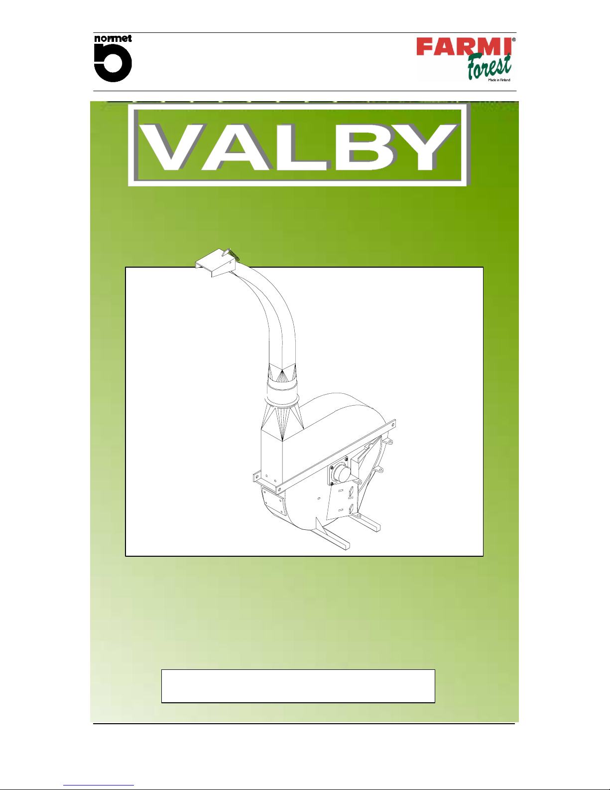
Farmi Forest Corporation VALBY CH 222 Guide

OPERATION, MAINTENANCE AND
SPARE PARTS MANUAL
CH 222 CHIPPER
B--USA--211002--JaK
www.normet.fi 03299750
03294030
Normet Corporation
Ahmolantie 6
FIN---74510 PELTOSALMI
FINLAND
Tel.+358(0)1783241
Fax. +358
(
0
)
17 823 606
It is very important to read this instruction
handbook thoroughly before using the machine!
CHIPPER CH 222
From machine: 329 8211--


OPERATION,MAINTENANCE
AND SPARE PARTS
CH 222 CHIPPER
www.normet.fi
03294030
--- 3 ---
1. TO THE OWNER---OPERATOR
Thank you for purchasing a Normet Corporation product.
Before we begin this manual, the people at Normet Corporation want you, the owner--
operator , to know this piece of equipment can be very dangerous if safety procedures
and warnings are ignored. Read this manual carefully page by page until you under-
stand it completely. Failure to do so will reslult in personal injury and / or equipment dam-
age.
All personnel including operators, maintenance crew, etc. should read this manual be-
fore start up.
This manual should be considered a permanent part of your machine and should remain
with the machine when you sell it.
IMPORTER:
NORTHEAST IMPLEMENT CO. RP.
P.O. Box 402
Spencer, N.Y. 14883
U.S.A
Tel. +1---607---589 6160
Fax +1---607---589 4026
E---mail valby@clarityconnect.com

SAFETY INSTRUCTIONS
CH 222 CHIPPER
www.normet.fi
03294030
--- 4 ---
2. TERMS AND SYMBOLS USED IN INSTRUCTIONS
Safety is a combination of operator com-
mon sense and alertness at all times
when the machine is being operated or
serviced.
THINK
SAFETY!
This message is used for general remind-
ersofgoodsafetypracticesortodirect
attention to unsafe practices. The mes-
sage will appear in your operator’s manu-
al and/or the sign will appear on the ma-
chine with the color combination of yel-
low and black.
CAUTION!
This message denotes a specific poten-
tial hazard. The sign will be displayed on
the machine in areas of potential hazard.
The sign will have the color combination
of yellow and black.
WARNING!
Thismessagedenotesthemostserious
specific potential hazard. The sign will be
displayed on the machine in areas of po-
tential hazard.
DANGER!
Messages labeled ”Important” will ap-
pear in your operator’s manual to provide
specific instructions for performing ad-
justments, services, etc. If these
instruc ---tions are not followed it could re-
sult in damage to the machine.
IMPORTANT!

SAFETY INSTRUCTIONS
CH 222 CHIPPER
www.normet.fi
03294030
--- 5 ---
3.SAFETY
3.1.GENERAL SAFETY
IMPORTANT!
Do not operate this machine until you have read and
understood the manual page by page.
Theownerofthismachineisresponsiblefor
instructing all operators and support personnel in the
operation and safety precautions of this chipper.
Proper training prior to operating the chipper is
obligatory.
D
DD
D
Inform everyone who works with the chipper about the risks and how they can
avoid accidents.
D
DD
D
Before the chipper is running, ensure that the working place is clear of any by-
stander within a minimum risk zone of 100 ft. (30 meter).
D
DD
D
Do not let children or untrained persons operate the chipper.
D
DD
D
Always have the chipper mounted on the 3--point hitch of the tractor. Other-
wise the chipper will tip over.
D
DD
D
There is a serious crushing hazard between tractor and chipper. Do not go be-
tween the tractor and the chipper in any case, for example when you are
mounting the chipper to the tractor.
D
DD
D
Check that the covers of the universal shaft are in their place and the ransmis-
sion chains are fastened.
D
DD
D
Safety goggles, earmuffs and a hard hat are obligatory when chipping. Use
respirator mask, if necessary.
D
DD
D
Do not wear loose clothing, loose sleeves, scarves or long uncovered hair
around moving parts of machinery. Also avoid gloves of poor condition or
with loose fitting, because they might get caught in the branches.
D
DD
D
Stay alert! Do not operate the chipper when fatigued, or under the influence of
alcohol or drugs.
D
DD
D
IMPORTANT! Never leave the chipper running and unattended.
D
DD
D
IMPORTANT! Failure to obey the warnings on the chipper or in the operator’s
manual will result in personal injury and / or death and / or equipment dam-
age.
D
DD
D
Check the material before you feed it. The material must be free from nails,
stones and all other materials that are not wood, paper or plastic. IMPOR-
TANT! Feeding wire and barbed wire into the chipper is very dangerous as it
might pull in the operator.
D
DD
D
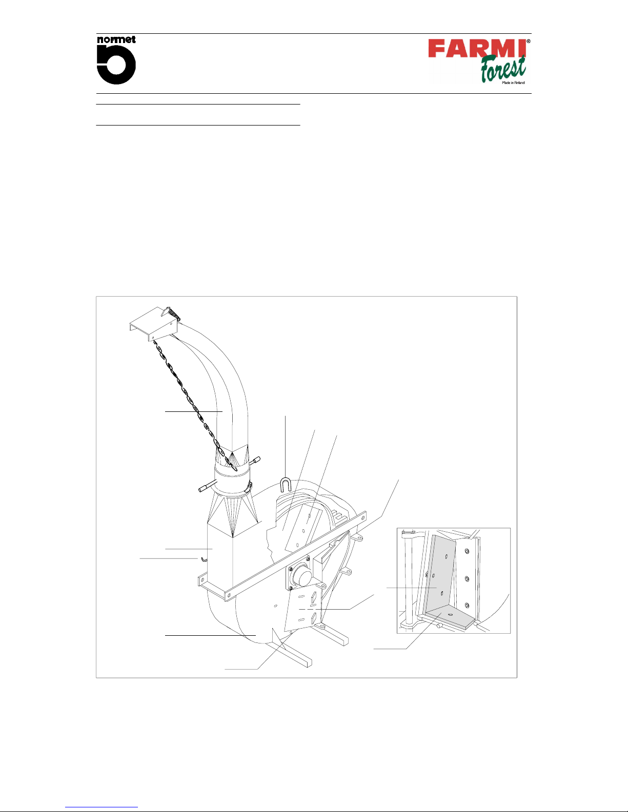
Make sure that no one is in the path of flying chips. Point the discharge pipe
away from windows, doorways and other areas where people or animals may
be.
D
DD
D
Keep the work area clean so there is nothing to trip over.

SAFETY INSTRUCTIONS
CH 222 CHIPPER
www.normet.fi
03294030
--- 6 ---
D
DD
D
Disengage the PTO, cut the engine and remove the keys before any mainte-
nance.
D
DD
D
Use only original parts replacements. IMPORTANT! Do not make any modifica-
tions.
D
DD
DCheck all moving parts. They should be fastened in place, in good working
condition and all shields and guards must be in place.
D
DD
DPoint the discharge downwind to prevent dust or chips from blowing onto
the operator.
D
DD
DIf a wood jams inside the chipper, cut the engine and wait for all movements
to stop before reaching inside the feed chute.
D
DD
D
Do not use the chipper indoors when you use it with a the tractor or with the
separate hydraulic motor. It’s possible to use the chipper indoors with the
electric motor use.
D
DD
D
You must be very careful when working indoors. Protect yourself against pos-
sible hazards like exhaust gas by sufficient ventilation, for dust that can catch
fire by cleaning your environment regularly.
D
DD
D
Always use the lock bolt before and during maintenance on the machine.
D
DD
D
Place the PTO shaft in the holding device when disconnected from tractor.
Risk of cutting injury or hits by flying debris.
Do not reach into the feed chute for any reason.
Failure to follow these instructions could result in serious
injury or death.
Danger!
3.2.SAFETY INSTRUCTIONS FOR THE HYDRAULIC FEEDER AND FEED CHUTE
D
DD
DIMPORTANT! Always also read the general safety instructions.
D
DD
DIMPORTANT! Do not ever put any part of your body inside the feed chute!
D
DD
DPrior to operating get familiar with the function and controls of the machine.
All functions must be in blameless condition.
D
DD
DTest the stop function.
D
DD
DBefore starting up, check that there is no debris or foreign objects in the
feed chute.
D
DD
DDo not work in front of the feed chute opening! Stand on the left side of the
chute when feeding, as the feed roller might jerk the wood up or to the right.
D
DD
DWhen checking malfunction, all controls must be in ”off” or in ”stop” posi-
tion.
D
DD
DLet go of the wood when the feed roller or the knives get hold of it. To feed
short pieces, push them in with longer ones.

SAFETY INSTRUCTIONS
CH 222 CHIPPER
www.normet.fi
03294030
--- 7 ---
3.3.SAFETY INSTRUCTIONS FOR THE HYDRAULIC UNIT
D
DD
DBefore performing lubrication work on any equipment, consult the manufac-
turer’s instruction manual and follow the recommended procedures.
D
DD
DBefore lubricating the machine, shut down the engine and stop the ma-
chine.
D
DD
DPressurized oil can be hazardous. Pressurized oil jet can penetrate skin and
cause serious injuries or death.
D
DD
DOccasional skin exposure with oil is not dangerous. If though you can not
prevent long ---time exposure use protective gloves and other protective
clothing.
D
DD
DKeep flammable material away from heat, sparks and open fire.
D
DD
DHot oil and oil spray can be hazardous. Small amounts swallowed or inhaled
do not usually cause toxication. Old oil is more dangerous than new.
D
DD
DIf oil has got into eyes flush them with cool water after which go to doctor.
Use safety goggles.
D
DD
DAvoid mixing lubricants of different grade and quality. Use only recom-
mended oils or oils with corresponding characters.
3.4.SAFETY INSTRUCTIONS FOR THE SEPARATE HYDRAULIC MOTOR USE
D
DD
D
Check the moving parts. They should be fastened in place, in good working
condition and all shields and guards must be in place.
D
DD
D
Inform everyone who works with the chipper about the risks and how they can
avoid accidents.
D
DD
D
Do not let children or incapable persons operate the chipper.Do not wear loose
clothing, loose sleeves, neckties or long uncovered hair around moving parts
of machinery.
D
DD
D
Disengage the PTO and turn the tractor off before you service the chipper.
D
DD
D
Use only original parts replacements. Do not make any modifications.
D
DD
D
Failure to obey the warnings printed on the chipper or in the operator’s manual
might result in a serious injury or death.
D
DD
D
When checking the malfunction, all devices must be in “off” position.
D
DD
D
Place the PTO shaft in the holding device when disconnected from tractor.

TABLE OF CONTENTS
CH 222 CHIPPER
www.normet.fi
03294030
--- 8 ---
1. TO THE OWNER---OPERATOR 3..........................................
2. TERMS AND SYMBOLS UDED IN INSTRUCTIONS 5.......................
3. SAFETY 6...............................................................
3.1. GENERAL SAFETY 5..............................................................
3.2. SAFETY INSTRUCTIONS FOR THE HYDRAULIC FEEDER AND FEED CHUTE 6..........
3.3. SAFETY INSTRUCTIONS FOR THE HYDRAULIC UNIT 7...............................
3.4. SAFETY INSTRUCTIONS FOR THE SEPARATE HYDRAULIC MOTOR USE 7..............
4. CHIPPER PRESENTATION 10............................................
4.1. FIELD APPLICATION 10............................................................
4.2. MAIN COMPONENTS 10...........................................................
4.3. DIMENSIONS 11..................................................................
4.4. TECHNICAL DATA 11..............................................................
5. PLATES AND STICKERS 12..............................................
6. ASSEMBLY AND MOUNTING 15..........................................
6.1. ASSEMBLY 15....................................................................
6.2. CUTTING THE PTO SHAFT TO THE CORRECT LENGHT 15............................
7. OPERATION 17.........................................................
7.1. USING THE CHIPPER 17...........................................................
7.2. TURNING THE CHIPPER OFF 17....................................................
8. SERVICE 18............................................................
8.1. TIGHTENING THE CLUTCH 18......................................................
8.2. PERIODIC SERVICE 18............................................................
8.3. LUBRICATION OF THE PTO SHAFT 18...............................................
9. KNIVES AND ANVIL 19..................................................
9.1. BEFORE SERVICING THE KNIVES 19...............................................
9.2. SHARPENING THE KNIVES 19......................................................
9.3. SHARPENING THE ANVIL 19.......................................................
9.4. ADJUSTING THE CLEARANCE BETWEEN KNIVES AND ANVIL 20......................
9.5. CHANGING THE SPLINED AXLE 21.................................................
9.6. MAINTENANCE SCHEMA 21.......................................................

TABLE OF CONTENTS
CH 222 CHIPPER
www.normet.fi
03294030
--- 9 ---
SPARE PARTS
03294030 CH 222 Chipper 22.. ...........................................
WHEN ORDERING SPARE PARTS, PLEASE INDICATE MACHINES TYPE FROM THE MACHINE PLATE,
SPARE---PARTS ORDER NUMBER, DESCRIPTION AND QUANTITY REQUIRED.
EXAMPLE: CH222, 43298410, Knife, 2 pcs.
Thread Millimeter Inch
M6 10 7/16
M8 13 1/2
M10 17 11/16
M12 19 3/4
M16 24 15/16
M20 30 13/16

CHIPPER PRESENTATION
CH 222 CHIPPER
www.normet.fi
03294030
--- 1 0 ---
4.CHIPPER PRESENTATION
4.1. FIELD OF APPLICATIONS
CH222 is a two --knife disc chipper/shredder. Chip
size is adjustble, making chips suitable for com-
bustion or industrial uses, soil improvement, dry
litter etc.
4.2. MAIN COMPONENTS
1.Upper chamber
2.Lower chamber
3.Disc
4.Knife
5.Vertical anvil
6.Horizontal anvil
7.Discharge pipe
8.Water holes
9.Lift point
10.PTO holding device
1
34
2
5
7
6
8
7
9
10
Fig.1. Main parts.

CHIPPER PRESENTATION
CH 222 CHIPPER
www.normet.fi
03294030
--- 1 1 ---
4.3. DIMENSIONS
660 (22”)
990--1092 (39”--43”)
965 (38”)
880 (35”)
260
(60”)
1150 (46”)
2920 (3175 optional)
115” (125” optional)
4.4. TECHNICAL DATA
Output 6,5--16m
3
/h, 229--565 in
3
/h,
Chip length 18 mm, 11/16”
Max timber diameter 250 mm, 10”
Power demand 26 -- 67 kW, 35 -- 90 HP
Rev. speed 540--1000 rpm
Number of knives 2 pcs.
Power source Tractor or stationary electric motor
Anchorage 3--point or bolted to base
Rotor diameter 1050 mm, 41
5
/
16
”
Rotor weight 240kg,500lbs
Bearings Spherical roller bearings
Discharge chute 360°rotatable
Opening of upper chamber Double hinge
Weight 530 kg, 1168 lbs
Sound pressure level
Sound power level
108 dB (A)
118 dB (A)

PLATES AND STICKERS
CH 222 CHIPPER
www.normet.fi
03294030
--- 1 2 ---
5.PLATES AND STICKERS
These decals and stickers must be found from chipper. Missing ones must be
renewed immediately.
8
1
3
5
4
27
10
6
9
2. 41014310
30140602
3. 4101750
CH 222
4. 40142080
41014310
41011750
40142080
30140602
20 __ __
1.

PLATES AND STICKERS
CH 222 CHIPPER
www.normet.fi
03294030
--- 1 3 ---
5.
7.
41015500 6. 41014170
41014170
41014270
8. 40141160
41014190
10. 41014110
41014110
41014270
40141160
9. 41014190
41015500

PLATES AND STICKERS
CH 222 CHIPPER
www.normet.fi
03294030
--- 1 4 ---
Plates and stickers for chipper CH 222
Part Order no. Description Remarks Qty.
1. 30140602 VALBY---sticker 1.... ..... ...................................................
2. 41014310 Safety precautions 1.... ..... ................................................
3. 41011750 Machine plate 1.... ..... ....................................................
4. 40142080 Safety goggles, earmuff and a hard hat are oblicatory when chipping 3.... ..... ...
5. 41015500 Do not operate this machine until the owner’s manual has been.... .....
completely read and understood, disconnect the PTO before service, be...................... ..
ware of cutting tools 1...................... ..............................................
6. 41014170 Turn PTO off and stop the engine before maintaining the chipper 1.... ..... .......
7. 41014270 Lifting point 1.... ..... ......................................................
8. 40141160 Rotation speed and rotation direction of the PTO shaft 1.... ..... ................
9. 41014190 Sharpening the knives 1.... ..... .............................................
10. 41014110 Beware of cutting tools 2... ..... ............................................

ASSEMBLY AND MOUNTING
CH 222 CHIPPER
www.normet.fi
03294030
--- 1 5 ---
6.ASSEMBLY AND MOUNTING
6.1.ASSEMBLY
DFasten the 3--point hitch lift bar with screw M16
(part 13 and 15, see spare parts list 03294030) to
the chipper frame. Try first the holes that move the
chipper farther away from the tractor. That posi-
tion increases the life of the universal shaft.
If the tractor can not lift the chipper from that posi-
tion or if the front end of the tractor becomes too
light, then move the lift bar in.
DTighten the nuts M16 to 260 foot pounds.
Fig.2. Guide piece.
DPlace the guide piece on the feed opening
DFasten the feed chute with pin (part 11)
DConnect the discharge tube (29) to the chipper.
Adjust the lid control with the chain.
DThe chipper must be mounted on the 3--point
hitch of the tractor. The chipper will tip over if it
is run without hooking it up to the 3--point hitch.
Cardan shaft recommendation:
Bondioli & Pavesi A6 + FF2 overload clutch + RA1
overrunning clutch or Walterscheid W2400 +
K92/4 (D) overload clutch + F3 overrunning
clutch. An overriding clutch must be used if the
tractor has a PTO--brake (for example Ford).
DCheck that the PTO shaft is at correct length.
6.2.CUTTING THE PTO SHAFT TO THE
CORRECT LENGHT
Caution !
If the PTO shaft is too long it might
bind when the three point hitch is lifted
up. Damage might be caused to the
bearings of the chipper or to the PTO
of the tractor. If the PTO shaft is too
long it must be cut. Both PTO halves
must be shortened by equal amounts.
DTurn the tractor off. Lower the chipper on a flat
surface.
DMount the chipper on the three point hitch of the
tractor.
DWith the chipper resting on the ground, see that
the splined shafts of the tractor and chipper are
horizontal.
Fig.3. Mark lenghts.
DConnect one shaft half to the chipper‘s PTO
and the other half at the tractor‘s PTO. Lay the
other PTO half on its side so that the end of the
shaft is one inch from the PTO--end of the chip--
per. Mark lengths required. The tubes must be
shortened so that they cannot reach the bottom
when the chipper is lifted or lowered.

ASSEMBLY AND MOUNTING
CH 222 CHIPPER
www.normet.fi
03294030
--- 1 6 ---
Fig.4. Cut the plastic shield.
DCut the plastic shield.
Fig.5. Cut the profile.
DCut a piece from profile tube which is as long as
the piece you cut off from the shield. Shorten
the other PTO shaft by the same length.
Fig.6. File sharp edges.
DFile sharp edges

OPERATION
CH 222 CHIPPER
www.normet.fi
03294030
--- 1 7 ---
7.OPERATION
7.1.USING THE CHIPPER
Warning!
Do not attempt to operate this chip-
per without proper training. Read
and understand the owner’s manual
before operating the machine.
Failure to heed the warnings printed
on the chipper or in the operators manual might
result in serious injury or death!
DTurn the tractor off.
DLower the chipper on its legs on a hard, level
surface so it will not tip over.
DTurn the chipper’s axle by hand to ensure that
the disk can turn freely (so that there are no for--
eign objects in the chipper).
DLook inside feedchute to ensure that it is empty.
DMake sure that all shields are in place and
intact. Removal of the shields is prohibited!
DDirect the discharge tube in desired position.
DStart up the PTO when the tractor runs at low
rpm and increase the rpm to operating speed.
Power required depends on the material to be
chipped and the sharpness of the knives.
DThe chipper is now ready for use.
DBefore feeding make sure that the material is
free from stones, nails and all other foreign
objects.
DWhen chipping wood, push the tree trunk inside
the feed chute until the knives touch the tree.
The chipper is self feeding, so let go of the tree
as soon as the knives touch it.
Caution !
Do not use chipper if temperature
falls below 23_F. This practice will
prevent risk of damage to the knives.
Also avoid chipping trees that are fro-
zen solid as they will not self--feed
well.
7.2.TURNING THE CHIPPER OFF
DReduce the tractor rpm to idle before shifting
the PTO to OFF--position. This is particularly
important on tractors with PTO brakes, such as
Ford.
On these tractors, after idling the tractor, you
should slowly move the PTO control lever to the
OFF--position.
Danger!
After turning the chipper off, wait for
all movement to stop; the disk contin-
ues rotating by flywheel moment
after the PTO has been discon-
nected.

LUBRICATING AND MAIN---
TENANCE INSTRUCTIONS
CH 222 CHIPPER
www.normet.fi
03294030
--- 1 8 ---
8.SERVICE
8.1.TIGHTENING THE CLUTCH
If the P.T.O clutch slips during normal operation,
it must be tightened.
DThe clutch is tightened by tightening the nuts
which press on the clutch springs.
DTighten every nut 1/4 of a turn.
DTry out the chipper.
8.2.PERIODIC SERVICE
Warning !
Always disengage the PTO and turn
the tractor OFF before you service or
repair the chipper.
Wait for all movement to stop before
reaching inside the feed chute.
Remove the keys so that the tractor
cannot be started up accidentally.
DAlways turn the tractor off before servicing or
repairing the chipper. Wait for all movement to
stop before service; the disk continues rotating
by flywheel moment after the PTO has been
disconnected.
DOpen the upper housing bolts M10 (32).
DLock the disk with the lock bolt (18).
DRemove or turn the feed chute to the side.
The bearings are greased at the factory with Shell
Alvania Grease R 3. A similar lubricant such as
Kendall L427 should be used by you. Avoid over-
greasing because it causes heat which reduces
lubrication.
DLubricate bearings every 200 hours or once a
year.
DCheck that the clearance between the knives
and the anvil is about 1/30 ”. See chapter 9.4.
DIf the chipper stands unused for long periods of
time, cover the knives with grease.
Make sure that the water drains on the lower
housing are open.
Lock bolt
Fig.7. Disk lock.
8.3.LUBRICATION OF THE PTO
SHAFT
DLubricate the P.T.O shaft before putting into
operation and frequently as shown in
schema below.
DApply grease to inside of outer telescopic
profile.
DWhen used in winter the guard tubes must be
greased to prevent them from freezing solid.
8h 8h
40h 20h 40h 8h
8h
When used in winter the
guard tubes must be greased to
prevent them freezing solid.
Swing joint sideways for greasing
Fig.8. PTO shaft’s lubrication points and fre-
quency of lubrication.

LUBRICATING AND MAIN---
TENANCE INSTRUCTIONS
CH 222 CHIPPER
www.normet.fi
03294030
--- 1 9 ---
9.KNIVES AND ANVIL
9.1.BEFORE SERVICING THE KNIVES
Danger !
ROTATING KNIVES
Don’t risk cutting injury or
beingstruckbyhigh
speed particles.
Wait for all movement to
stop before reaching inside the feed chute.
Failure to follow safety precautions could result
in serious personal injury or death.
DTurn the tractor off.
DOpen the upper housing bolts M10 (32). Turn
the upper housing to the side.
DLock the disk with lock bolt (18).
DRemove or turn the feed chute to the side.
DUse protective gloves when handling the kni--
ves.
9.2.SHARPENING THE KNIVES
You will notice the need to sharpen the knives
when:
-- Trees do not self--feed well.
-- The power requirement is increased.
-- The smoothness of the chip surface is decrea--
sed.
Keep the knives with their original pairs. That way
the knives will be worn equally and the disk stays
in balance.
DRemove the 3 locknuts M12 (3.5) behind the
knife frame.
Fig.9. Remove the knife fastening bolts.
DRemove the knife--fastening bolts M12 (3.3,
they are threaded through the disk. Turn the
wrench so that your knuckles will not touch the
knife if the wrench slips.
30
o
Fig.10. 30 degree angle.
DSharpen the knives at a 30 degree angle.
Caution !
Use gloves when removing or han-
dling the knives, Turn the wrench so
that your knuckles will not touch the
knife if the wrench slips.
Avoid getting the knife hot when sharpening.
Sharpen both of the knives the same amount.
Certain corn choppers use the same style of knife
as the Valby Chipper (Papec for example).
Automatic grinders to service this style of knife
can thus be found at some implement dealers. Of
course, grinders to service chipper knives are
available from grinder and knife manufacturers.
DFasten the knife and tighten the bolts to 50 foot
pounds.
DAdjust anvil clearance if needed.
9.3.SHARPENING THE ANVIL
If you notice wear or rounding of the inner edge of
the anvil, sharpen the anvil so that the original
angles are retained.

LUBRICATING AND MAIN---
TENANCE INSTRUCTIONS
CH 222 CHIPPER
www.normet.fi
03294030
--- 2 0 ---
9.4.ADJUSTING THE CLEARANCE
BETWEEN KNIVES AND ANVIL
Usually you can sharpen the knives 10 times before
there is a need to adjust the anvil. Adjust the anvil if
the gap to the edge of the knives is over 1/20”.
Anvil lock screws
Anvil adjuster
Anvil adjuster
Fig.11. Adjusting the anvil.
DLoosen the four bolts M16 (42, 43) that fasten
the anvils (7, 8). One of the bolts is under the feed
chute.
DTurn the disk so that a knife comes against the
anvil. Move the anvil with the adjusting nuts
(46) until the clearance
1
/
30
of an inch.
Tighten adjusting nuts. Tighten anvil lock bolts
to 144 foot pounds.
CHIP LENGTH
CLEARANCE 1/20” -- 1/30”
TIGHTENING TORQUE 144 ft.lb
TIGHTENING TORQUE 50 ft.lb
DISK (3)
KNIFE (3.2)
KNIFE SCREW (3.3)
ANVIL LOCK BOLT (42, 43)
ANVIL ADJUSTING NUTS (46)
HORIZONTAL ANVIL (7)
VERTICAL ANVIL (8)
Table of contents
Other Farmi Forest Corporation Chipper manuals
Popular Chipper manuals by other brands

Craftsman
Craftsman 79960 owner's manual

Portland
Portland 61714 Owner's manual and safety instructions

Farmi Forest
Farmi Forest CH18 PTO Operation and maintenance manual

Farmi Forest
Farmi Forest CH10 OPERATION, MAINTENANCE AND SPARE PARTS MANUAL

Wallenstein
Wallenstein BXC34 Operator's manual

Wallenstein
Wallenstein BXC34 Operator's manual