FarmTek Growers Supply HydroCycle User manual

1
Revision date: 10.12.18
113702
Designed to grow healthy plants without soil using mineral-nutrient solutions.
HydroCycle 9"
Pro NFT Deep System
©2018 Growers Supply
All Rights Reserved. Reproduction
is prohibited without permission.

2113702 Revision date: 10.12.18
REQUIRED TOOLS
The following list identifies the main tools needed
for assembly. Additional tools and supports may be
needed.
• Tape measure, marker, and chalk line
• Variable speed drill (cordless with extra
batteries works best)
• Hammer and gloves
• Long level to set tank
• Utility knife
• Adjustable pliers and assorted hand tools
common to plumbing and electrical work
• 1-3/8", 2-1/2", 3", and 5" hole saws and 7/8"
Forstner bit (required)
• 9/32" drill bit
READ THIS DOCUMENT BEFORE YOU BEGIN
Thank you for purchasing this NFT system. When properly assembled and maintained, this system will provide years of reliable service. These instructions
include helpful hints and important information needed to safely assemble and properly maintain the system. Please read these instructions before you begin. If
you have any questions during the assembly, contact Customer Service at 1.800.245.9881 for assistance.
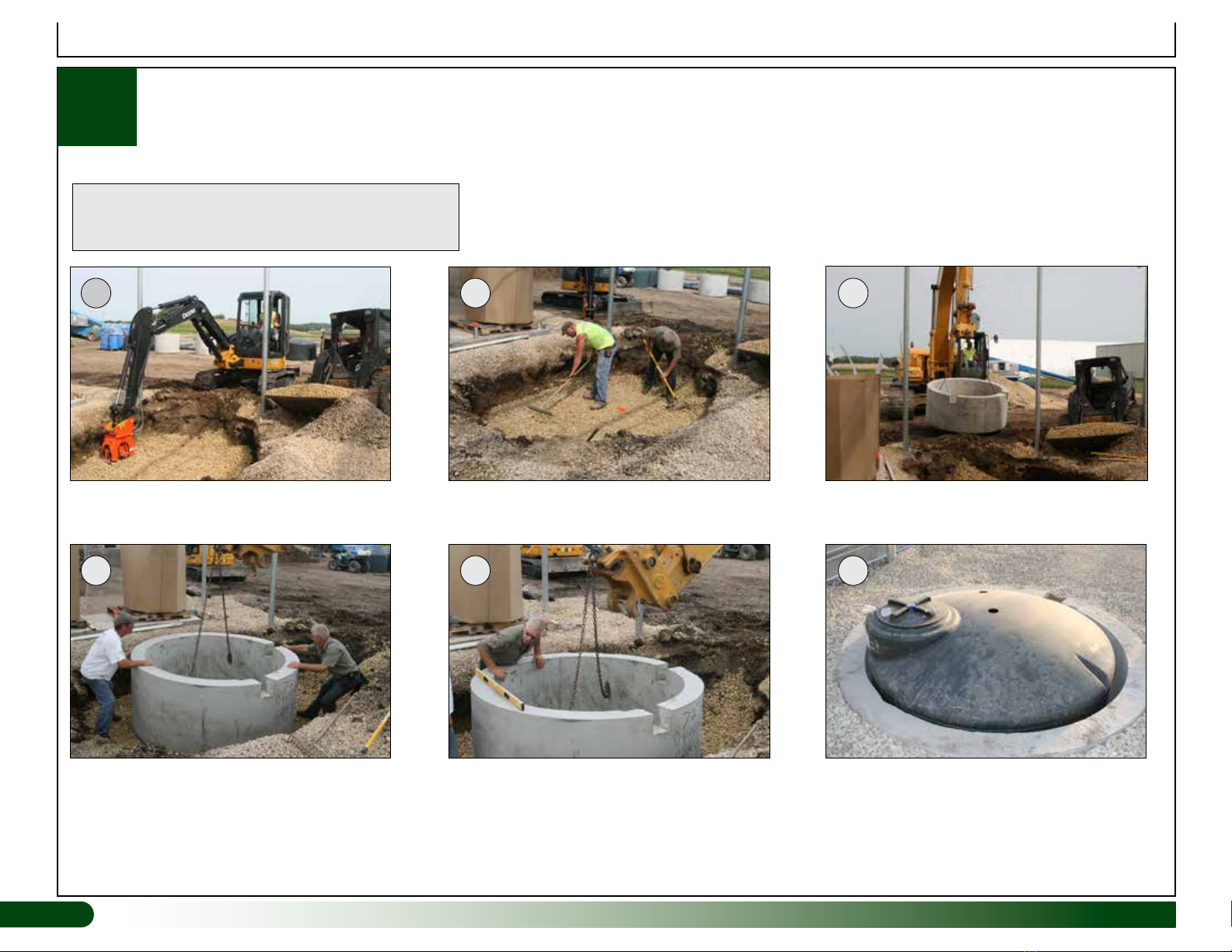
ASSEMBLY PROCEDURE
Following the instructions as presented will help
ensure the proper assembly of your NFT system.
The steps outlining the assembly process are as
follows:
1. Verify that all parts are included in the
shipment. Notify customer service for
questions or concerns. See below.
2. Read and understand these instructions and
the information included with the shipment
before you begin.
3. Gather the tools and assistants.
4. Assemble the system.
5. Use the system.
Important Information
SAFETY PRECAUTIONS
• Wear eye protection.
• Wear gloves when cutting pvc tubing.
• Use a portable GFCI (Ground Fault Circuit
Interrupter) when working with power tools and
cords.
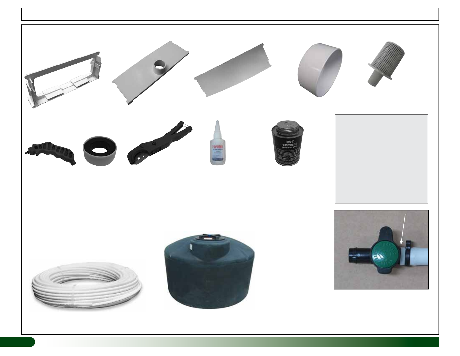
UNPACK AND IDENTIFY PARTS
The following steps will ensure that you have all
the necessary parts before you begin assembly.
1. Unpack the contents of the shipment and
place where you can easily inventory the
parts. Refer to Bill of Materials/Spec Sheets.
2. Verify that all parts listed on the Bill of
Materials/Spec Sheets are present. If
anything is missing or you have questions,
consult the Pictorial Parts Guide and
all diagrams for clarification, or contact
Customer Service.
NOTE: At this time, you do not need to open
the plastic bags containing smaller parts
such as fasteners or washers (if equipped).
WARNING: Enlist the services of an
experienced electrician when connecting
power to the pump and other electrical
devices—required.
All wiring to be completed according to
established codes and practices.
DROWNING HAZARD: Never leave the
tank cover off when tank is unattended.
Never allow children or others within the
boundary of the pump station at any time.
Always have an assistant present when
completing tank cleaning and system
maintenance to prevent accidents.
Disconnect the pump when performing any
system maintenance.
FERTIGATION SYSTEMS
A fertigation system can be connected to your
NFT system to provide constant control of pH
and nutrient levels in the nutrient tank.
Remember to allow space to mount the system
when preparing the pump station site.
To assemble and connect a fertigation system
to this NFT system, consult the information
provided with the fertigation system.
NOTE: Additional pvc tubing and fittings
may be required to connect the fertigation
system. Purchase locally or call your sales
representative for additional information.

3
Revision date: 10.12.18 113702
Important Information
PICTORIAL GUIDE
The following graphics and photos will help identify the different parts of the NFT system. (Some parts may
not be shown.) Keep all fittings in the shipping bags until they are needed.
WF1384 111045 WF6777
WF4067
WF2350 WF1982
111598 111599
WF1574
WF6671
110730 111048 AC2804
111698
WF3511
111580 111150
111623 111624 & 111625 111626 111146 Pump111151 Strainer
111160
2" Dual Lite Disc Filter
ATTENTION: A 7/8" Forstner
bit is required to drill the holes
to install the 111598 grommets.
This bit is not included.

4113702 Revision date: 10.12.18
PICTORIAL GUIDE (continued)
Important Information
112633
End Cap w/ Outlet
1112631
Joiner
111157 (550 Gallon Tank)
112632
End Cap No Outlet CC2652
WR1095 Tape 112509
Adhesive
Plastic Pipe and
Tube Cutter
111627
3/4" White Polyethylene Tubing
110743
3MM Punch
ATTENTION: Install all fittings so
they are fully inserted into the 3/4"
tubing. Use a hair dryer or hot water
to gently heat the tubing for easier
installation. Do not overheat!
Heat tube with
a hair dryer
for easier
assembly. Do
not overheat!
IMPORTANT: Do not use WF6990
PVC cement to attach end caps to
the GT80 channels. Use the 112509
adhesive only.
111154 Strainer
WF6990 PVC Cement and
113372 Purple Primer
PVC PRIMER & PVC CEMENT
Follow all directions printed
on pvc primer and cement
containers. Purple color of
primer does not fade! Use
caution during application
to reduce spills and over
application at joints.
Prime all joints before
assembly.

5
Revision date: 10.12.18 113702
Getting Started
ASSEMBLY PROCEDURES
Below are the main steps to assemble the NFT system. Procedures can
occur simultaneously when assistants are available, or each procedure can
be completed before moving onto the next. In most instances, the site and
available space drive which procedures can be completed first before moving
onto the next. Review this entire guide before beginning to ensure that you
understand how to position and connect the different components.
1. Review this guide and all sample layout diagrams and prepare the site.
2. Prepare and set the nutrient tank in position as shown in the diagrams.
3. Assemble and connect all pump, filter, and tank plumbing.
NOTE: If a fertigation system is used for the system, identify where
that system will be mounted and where the storage tanks will be set.
Review the photos near the back of this guide for an example. Follow the
instructions provided with the fertigation system to properly connect it to
your NFT system.
4. Determine the materials needed to support the individual NFT channels.
5. Assemble all NFT channels and position on the customer-supplied
supports.
6. Assemble and install the 4" return line from the channels to the tank.
7. Assemble and connect all 3/4" and 1-1/2" supply lines to the NFT channels
and connect to the pump station.
8. Add solution to tank, prime the pump according to pump documentation,
and test system. Check for leaks and proper flow to each NFT channel.
9. Read and follow the care and maintenance information.
BASIC CARE AND MAINTENANCE
Daily
1. Check all 1/4" supply tubes at each channel to ensure proper flow. Clean
and replace as needed.
2. Check all fittings, tubes, and pipes for leaks.
3. Check pump and filters for leaks.
4. Ensure that the by-pass and recirculation valve is set properly to allow
solution to flow back into the tank.
5. Check pressure gauges to ensure a constant pressure across the filter.
6. Check PH/EC/TDS levels in the tank according to requirements for the
plants that are growing.
7. Inspect all electrical connections and wires for damage or corrosion.
Weekly
1. Disassemble and clean the 111160 disc filter according to the instructions
sent with the filter.
2. Inspect the inside of the tank to ensure that there is no excess plant debris.
ATTENTION: Do not check tank without an assistant present. Keep the
cover tightly in place at all times. Do not allow children or others near the
tank during inspections and scheduled maintenance.
Monthly
1. Clean the 111154 strainers inside the tank. Excess plant matter can clog
strainers and may be an indication of distressed crops. Perform this
procedure more often if needed.
2. Inspect the exterior and top of tank.
3. Keep pump station and surrounding areas free of excess debris and other
materials common to a growing facility.
4. For best results, drain and clean the inside of the tank at least 2-4 times a
year depending on conditions.
5. Check drain tube. Clean and sanitize as needed for best results. Check
drain tube slope to ensure proper drainage of tube.
WARNING: Enlist the services of an experienced electrician when
connecting power to the pump and other electrical devices. All wiring to
be completed according to established codes and practices.
DROWNING HAZARD: Never leave the tank cover off when tank
is unattended. Never allow children or others within the boundary
of the pump station at any time. Always have an assistant present
when completing tank cleaning and system maintenance to prevent
accidents. Disconnect the pump when performing any system
maintenance.

6113702 Revision date: 10.12.18
ATTENTION: Customer is responsible for supplying the necessary materials for and to construct a platform for each set of 20' channels. System is designed
to allow channels to drain into the 4" drain tube, which is placed on the finished grade. To ensure proper drainage and assembly, the 20' channels must be
higher than the 4" drain tube. See Side View below. Recommended slope from the high end of the 20' channel to the drain or low end is 2"- 4".
Sample Layout (Top & Side Views)
The diagram below shows one way to position the NFT channels, work areas, and 10' x 10' pump and tank area. Use this diagram when planning to assemble
your NFT system. Review all diagrams and photos in this guide before you begin. Building size and contents may require adjustments of the layout. Changing
the layout may require additional materials for connections, plumbing, and electrical components. Materials can be purchased locally, or contact your sales
representative for additional purchases. Customer is responsible for all additional materials. These are not included.
Side View
Top View
IMPORTANT: Shaded areas in the Top View diagram
below represent the customer-supplied platforms used to
support the individual channels throughout their length. If
full supports are not used, support each channel every 2' to
3' to prevent deflection and to promote adequate drainage.
Full supports as shown are best for channel performance
and optimum plant growth. Recommended slope is 2" to 4"
depending on plants and root mass.

7
Revision date: 10.12.18 113702
Sample Layout
10'
10'
24"
on-center
24"
on-center
48"
on-center
Below is a sample layout. When constructing supports for the channels, ensure
that the supports slope toward the 4" drain tube. See diagram that follows.
Finished Grade
When building platforms to set channels on, ensure that the
dimension from the finished grade to the top of the platform is
3-1/2". This is at the low/drain end of each channel where 4"
drain tube is placed. Channels must slope toward the drain end.
3-1/2"
4" Drain
Tube

8
8113702 Revision date: 10.12.18
Prepare Site and Set Tank
1Site preparation is important. Review the photos below and enlist the help of a professional contractor when setting the tank. Tank must be set
inside a concrete sleeve or similar structure. Tank is not designed to be buried without a protective bunker; it is not an underground tank.
1
4
2
5
3
6
IMPORTANT: Before setting the tank in the sleeve,
ensure that the sleeve is free of rocks or other debris
that could puncture the tank when it is filled.

9
Revision date: 10.12.18 113702
Pump and Tank Plumbing Views
2Assemble the pump station as shown. Review the
following information before you begin:
• Drill all holes in the top of the tank after
the tank is set and in its final position. See
diagram to the right. Do not drill the fertigation
hole if fertigation system is not used.
• Use a 2-1/2" hole saw to drill all holes for the
1-1/2" pvc pipe.
• Use a 3" hole saw to drill all holes for the 2"
pvc pipe.
• Use a 5" hole saw to drill the drain return hole
for the 4" pvc tube.
• Install all gaskets before you insert pvc pipe.
Greenhouse Back
Wall–Top View
Supply to Pump—
Top Center
Hole for Fertigation
System if used.
Hole for
Vent
By-Pass and
Recirculation Line
Tank—Top
View
IMPORTANT: Drill only the holes that are needed. Dry
fit all plumbing, mark hole location, drill hole, check fit,
then prime and cement pipes and fittings as needed.
111626
Install
111624
gasket here.
Install
111624
gasket here.
Pump
111150
WF3511
WF1574
WF1574
111151
Finished Grade
Customer-Supplied
Pump Mount
Install
111625
gasket here.
1-1/2"
PVC
USE PVC PRIMER & PVC CEMENT FOR ALL
NON-THREADED PVC CONNECTIONS UNLESS
OTHERWISE INSTRUCTED.

10
10 113702 Revision date: 10.12.18
Pump and Tank Plumbing Views
2
psi
0
5
10
15 20
30
25
psi
0
5
10
15 20
30
25
Greenhouse
Back Wall–Top
View
Finished Grade
Return from NFT channels
Outlet for main supply line
to NFT channels.
See View B on
the next page.
See View A on the next page.
WF1574
WF1574
WF1574
WF1384
WF3511
Install 111625 gasket here.
FERTIGATION SYSTEMS: To assemble
and connect a fertigation system to this NFT
system, consult the information provided with
the fertigation system.
Install 111623
gasket here.
Position of the 4" drain tube return gasket
depends on how deep tank is set and the
bunker design around the tank. Drill gasket
hole using a 5" hole saw.
Customer-supplied support
for main pump.
USE PVC PRIMER & PVC CEMENT FOR ALL NON-THREADED
PVC CONNECTIONS UNLESS OTHERWISE INSTRUCTED.

11
Revision date: 10.12.18 113702
Pump and Tank Plumbing Views
View B—Inside Tank Assembly
1-1/2" PVC
Tubing
WF1384
WF1574
111154
WF1574
111154
View A
NOTE: Cap the top outlet
of the 111160 filter.
ATTENTION: During assembly, wrap all fitting threads
with tape before connecting the different parts. (Does
not apply to fittings inside the tank.)
Install filter at a height that allows disassembly and
cleaning of the filter.
Secure all pvc fittings using pvc primer and pvc cement.
Apply according to the instructions included with those
products. See note below for the assembly inside the
tank.
During the installation of the 111160 filter, confirm water
flow direction and install filter accordingly.
IMPORTANT: Do not cement the fittings for the in-
tank assembly. This assembly may need disassembled
and removed from the tank for maintenance.
Before assembly, measure the main access hole to
determine the maximum width of the in-tank assembly.
ASSEMBLY NOTE: These diagrams identify the recommended
assembly configurations. Slight changes may be necessary due to
the specifics of each individual building and related systems.
Additional fittings and pvc may be needed if changes are made to
these suggested assemblies. Contact your sales representative for
information and to purchase additional parts if needed.
2
PVC PRIMER AND PVC CEMENT
USE PVC PRIMER & PVC CEMENT FOR ALL NON-THREADED
PVC CONNECTIONS UNLESS OTHERWISE INSTRUCTED.
ATTENTION: For easier cleaning, do
not cement strainers to elbows.
psi
0
5
10
15 20
30
25
psi
0
5
10
15 20
30
25
WF6777
1-1/2" PVC
Tubing
WF6777
WF2350 WF2350
111160
From Tank Out to NFT
Channels
111580
WF4067
WF6671
WF4067
WF6671

12
12 113702 Revision date: 10.12.18
3
Complete these steps:
1. Assemble channels on a flat surface. Take two (2) 112625 10' channels
and attach one 112632 end cap to one channel and one 112633 end cap
to the other channel using the 112509 adhesive. See photos A through D.
Apply adhesive inside and outside the channel.
ASSEMBLE THE 112625 10' NFT CHANNELS
2. Set channels aside and allow adhesive to dry.
3. Take the remaining channels and end caps and repeat Steps 1-2 to attach
the end caps to the channels—one end cap per channel.
NOTE: Be sure to coat all edges and seams of the end caps as shown to
prevent leaks. See photos E and F.
4. After adhesive has set, take one 112631 joiner and connect two (2)
channels to create a single 20' assembly. (See photo G.) One channel
should include a plain end cap and one channel should include an end
cap with an outlet.
ATTENTION: Do not connect two channels that have the same end cap.
Use assistants to help move and flip the channel.
5. Set the 20' channel in position where it will used and allow adhesive to dry.
Position the end cap with the outlet where the 4" pvc drain pipe will be.
6. Repeat the steps to construct the remaining 20' channels. There will be
eight (8) 20' channels for this system.
7. Finally, slide a 45° elbow (111045) onto each end cap. Install fitting with
the open end pointing down in the 6:00 o'clock position. See Photos H & I.
Repeat to install all elbows.
NOTE: Do not cement elbow to end cap at this time. If connection leaks,
remove elbow, dry the surfaces, and secure elbow using pvc primer
(113372) and pvc cement (WF6990).
8. Continue with the next procedure.
Apply adhesive in a well-ventilated area. Read the
container information for additional precautions.
Assemble NFT Channels
ATTENTION: Each 20' NFT channel assembly includes one
112633 end cap with an outlet and one 112632 plain end cap.
A B
C D
H
111045
Elbow
111000 Channel (12')
open
top-inside
channel
bottom
EF
I
Bottom of
Channel Bottom of
Channel
Open Top of
Channel
112631
Joiner
G
Coat channels and
joiner with thin film of
adhesive (inside and
outside) and connect
the components.

13
Revision date: 10.12.18 113702
4PREPARE THE 10' CHANNEL LIDS (112626)
Prepare Channel Lids
For this NFT system, channel lids are without plant holes. Hole spacing and size can vary depending on what plants are grown and size of plant medium.
Typical spacing for 3" holes is 16" on-center for growing tomatoes. If your intended crop requires different hole size and spacing, adjust as needed. Complete
these steps to prepare lids:
1. Select two (2) of the 10' channel lids (112626), place end-to-end on a flat surface, and mark the center of the top at each end.
2. Take a chalk line filled with non-permanent chalk, stretch it from end-to-end, align with the center marks, and snap the line.
3. Mark the center of the first hole at 12" from the one end. From that mark, mark the remaining hole positions at 16" on-center along the chalk line. There will
be fifteen (15) holes for each 20' channel. Mark lids at the joint where they meet to ensure correct alignment when installing on the 20' channel.
4. Place lids on scrap plywood (or similar material) for backing (if desired) and drill holes at each mark using a 3" hole saw bit.
5. Rinse the lids to remove all shavings so these will not plug the nutrient circulation system. Install this first pair of 10' lids on one 20' channel. Use the
alignment mark when snapping lids on channel to ensure proper hole spacing and assembly.
6. Repeat steps to drill the remaining lids and install these on the remaining channels. For best growing results, install the lids on adjacent channels so holes
are offset as shown in the diagram below.
7. Continue with the next procedure.
Install lids so holes are offset for optimum plant growth.
12" 16"
120" 120"
Mark each end of
lid at the center.
Center Chalk Line
X
Mark for alignment.

14
14 113702 Revision date: 10.12.18
5
Prepare and Install 4" Drain Tube
PREPARE AND INSTALL 4" PVC DRAIN TUBE
Two 10' sections of 4" pvc are included for the drain tube. This tube runs between the two banks of channels and back to the in-ground tank. Consult the
sample layout diagram presented earlier in this guide for typical location. Complete these steps:
1. Using the pvc primer and pvc cement, connect the two pieces of 4" pvc (CC2651) by sliding the plain end of one into the belled end of the other. Allow the
cement to set for a few minutes.
2. Place assembly into position on floor between the 20' channel assemblies. Measure 12" in from the plain (non-belled) end and mark.
3. From the mark in Step 2, measure the required length of the drain tube and mark that location. Measure toward the belled end.
4. Cut tube to length by removing the belled end. Tube will have two (2) plain ends when finished.
5. Insert the plain end (with the mark) into the tank gasket to the line made in Step 2. Wet the tube end for
easier installation.
Apply primer and cement, slide together, and allow cement to set.
12"
Insert this end into tank to this line. Cut tube to length. If the full length is
needed for your setup, remove only
the belled end of the pipe assembly
to install the 4" cap.
psi
0
5
10
15 20
30
25
psi
0
5
10
15 20
30
25
Outlet for main supply line
to NFT channels.
Finished Grade

15
Revision date: 10.12.18 113702
5
Prepare and Install 4" Drain Tube
6. Adjust tube position so it is centered between channels. Anchor the free end in
place using blocks or a sand bag.
7. Using a chalk line filled with non-permanent chalk, mark the center of the 4" drain
tube. See dashed line in the diagram to the right.
8. Next, pull the first set of channels toward the drain tube until the 45° drain elbows
touch the tube.
Anchor this end to drill channel drain holes.
9. Set the 24" on-center spacing between the two channels.
10. Mark the center of the drain elbows/NFT channels on the 4" drain tube.
PREPARE AND INSTALL 4" PVC DRAIN TUBE—continued
Mark center of elbow/NFT channel
on the drain tube and set the 24"
on-center spacing.
24"
on-center

16
16 113702 Revision date: 10.12.18
5
Prepare and Install 4" Drain Tube
PREPARE AND INSTALL 4" PVC DRAIN TUBE—continued
11. Remove "Hole Template for Drain Tube" page from the back of this guide,
fold it, and cut out the 1-3/8" holes using a scissors.
12. Place template over the 4" tube. Align
the center lines as noted on template
and mark the center of each hole.
13. Remove template and drill holes using
a 1-3/8" hole saw bit and drill. Have
an assistant hold 4" pipe in place while drilling holes. Use light pressure on
drill. Do not force bit. Keep hands away from bit during drilling. There
are four (4) holes for this first set of channels.
14. Move to the next set of channels and repeat the steps to drill the remaining
four (4) holes. Recommended spacing between the two sets of channels
for this example is 48". Adjust spacing as needed for your application.
15. After drilling holes, remove tube from tank and rinse. Tube must be clean to
prevent shavings from clogging filters and 1/4" supply tees and lines.
16. Slide tube end back into the tank gasket using the line made in Step 2 as a
guide. Do not insert drain elbows of channels into 4" drain tube at this time.
17. Continue by installing the nutrient supply plumbing.
48"
on-center
(Step 14)
1st set of holes.
2nd set of holes.
Step 14

17
Revision date: 10.12.18 113702
INSTALL THE NUTRIENT SUPPLY LINES—OVERVIEW
Prepare and Install Nutrient Supply Lines—Overview
All NFT channels are feed by a main 1-1/2" pvc supply pipe. For this example,
the pipe runs from the output side of main pump, down to ground level, and
along and parallel with the 4" drain tube. See dashed line.
BASIC ASSEMBLY PROCEDURE:
1. Layout and connect the 1-1/2" main supply line. Dry fit all connections. Do
not prime and cement until all grommets and fittings are installed. Use the
WF1982 coupling to connect the individual sections of 1-1/2" pvc tube.
2. Drill 7/8" grommet holes in the 1-1/2" pvc supply line(s) and install the
111598 grommets and 111599 adapters. See Procedure 7 for drilling and
installation details.
3. Install the 3/4" supply lines as described in Procedure 8.
psi
0
5
10
15 20
30
25
psi
0
5
10
15 20
30
25
Finished Grade
1-1/2" PVC
Supply Tube
1-1/2" PVC
Supply Tube

18
18 113702 Revision date: 10.12.18
PREPARE THE 1-1/2" PVC NUTRIENT SUPPLY LINE
6
Prepare and Install Nutrient Supply Lines
Complete these steps:
1. Construct the 1-1/2" pvc main supply line using the 90° elbows, WF1982
couplings, and 1-1/2" pvc. Do not cement connections at this time.
2. Review diagram at the right to determine location of the four (4) 3/4" fittings.
Mark each location on the assembled pvc tube.
ATTENTION: Each channel is feed by a single 3/4" supply line that typically
runs along the channel. Smaller, 1/4" tubes distribute nutrient solution from
the 3/4" line to the channels at evenly spaced positions along the channel.
The above diagram identifies the different parts and their locations. Use
it to assemble the 3/4" supply tube using the 111627 white tubing. When
assembled and installed, tube runs along the bottom of the GT80 channel
and on top of the customer-supplied supports for the GT80 channels.
3. Complete the procedure on the next page to install the gromments and
fittings in the 1-1/2" pvc supple line.
1-1/2"
PVC Supply Tube
4" Drain
Tube
110730
Tee Fitting
AC2804
Valve
111048 Tee
Barb
111598 grommet
& 111599 adapter
secured using a
ratchet clamp.
1-1/2" PVC
1/4" Tubes (Procedure 9)
111698
4" Drain Tube
Step 2: Install grommet
and adapter here.
Install CC2652 pvc cap anytime
after tube is installed and before
system is in operation. Do not
cement.
WF1982 Coupling
(Actual position may differ.)
Step 2: Install grommet
and adapter here.

19
Revision date: 10.12.18 113702
1-1/2" PVC SUPPLY LINE INSTALLATION DETAILS
7
1-1/2" PVC Supply Line Installation Details
Complete these steps to install the 111598
grommets and 111599 adapters.
1. After marking the 1-1/2" tube, drill a
7/8" hole at each position using the
7/8" Forstner bit (required).
2. Disassemble 1-1/2" pvc supply line
and clean tubes to remove shavings.
NOTE: Mark tubes to ensure
reassembly in same order if needed.
3. Reassemble and secure all
connections using pvc primer and
pvc cement. Apply according to
directions printed on containers.
4. Install a 111598 grommet in each hole.
There are four (4) holes in all.
5. Take one 111599 adapter and insert
the tabbed end into the grommet. Wet
the adapter for easier installation.
6. Carefully press adapter into grommet.
Place a stiff piece of flat stock against
adapter end to press it into place if
needed. Do not use a hammer or
similar tool to pound adapter into
grommet!
7. Repeat steps to install grommets and
adapters in the remaining holes in the
1-1/2" pvc supply line.
8. Continue with the installation of the
3/4" supply lines, fittings, and valves.
7/8" Forstner Bit—required. Additional purchase required. Use only a Forstner bit to
drill this hole. Other hole saws and bits may cause the grommet and adapter to leak.
111598
Grommet
111599
Adapter
Tab
Tab

20
20 113702 Revision date: 10.12.18
83/4" SUPPLY TUBE INSTALLATION—POLY TUBING (111627)
3/4" Supply Line Installation Details
Complete these steps to construct the 3/4" supply tube:
1. Measure the distance from the 1-1/2" supply pvc to the end of the first 20' channel and add 12".
2. Cut a piece of 3/4" tubing from the roll of 111627 tubing to the length found in Step 1.
3. Using the diagrams on this page and page 18, construct the supply line by adding the AC2804 valves and securing
them with the 111698 ratchet clamps. Gently squeeze the clamps with a pliers to secure each connection.
4. Repeat the steps as needed to construct a 3/4" supply tube for each pair of GT80 channels.
5. After constructing the long 3/4" tubes, add and secure a vertical 3/4" tube and tee fitting assembly to each adapter
installed in the 1-1/2" pvc supply tube. Height should be level with the platform the channels are mounted on.
6. Next, connect a long, horizontal tube to each outlet of the tee fitting and secure using the ratchet clamps.
7. Contine by installing the tee barbs and 1/4" tubes.
Step 1: Measure this distance and add 12".
1-1/2" PVC
A
B
Side View
A
B
Other manuals for Growers Supply HydroCycle
1
Table of contents