FarmTrack 675 User manual

Kullanım Kılavuzu
Farmtrac 675/675DT
|
|

2
Contents
page
INTRODUCTION .................................................................................................................................4
1. GENERAL INFORMATION .............................................................................................................6
1.1. Identification data..........................................................................................................................6
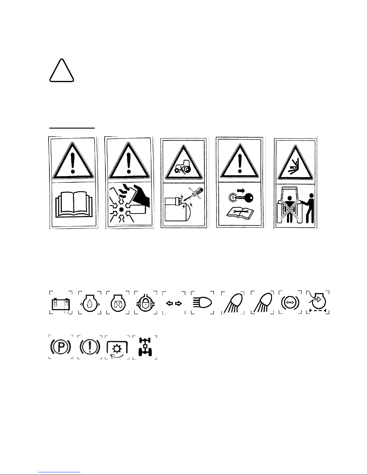
1.2. Safety precautions. .......................................................................................................................6
1.3. Fire precautions. ...........................................................................................................................9
1.4. Warranty.....................................................................................................................................10
1.5. Tractor delivery to purchaser.......................................................................................................10
2. TECHNICAL SPECIFICATION......................................................................................................12
2.1. Engine.........................................................................................................................................12
2.2. Electrical System.........................................................................................................................13
2.3. Transmission...............................................................................................................................13
2.4. Hydraulic lift system....................................................................................................................15
2.5. Three-point linkage. ....................................................................................................................15
2.6. Coupling devices.........................................................................................................................15
2.7. Steering system. .........................................................................................................................15
2.8. Wheels & axles...........................................................................................................................16
2.9. Braking system. ..........................................................................................................................16
2.10. Tractor weight...........................................................................................................................17
2.11. Tractor dimensions....................................................................................................................17
3. INSTRUMENT PANEL & CONTROL DEVICES............................................................................18
3.1. Instrument Panel.........................................................................................................................18
3.2. Control levers and pedal.............................................................................................................20
3.3. Tractor cab..................................................................................................................................23
3.4. Operator’s seat adjustments ......................................................................................................24
4. OPERATION..................................................................................................................................25
4.1. Tractor running in........................................................................................................................25
4.2. Starting and stopping the engine.................................................................................................25
4.3. Driving the tractor........................................................................................................................27
4.4 Power take-off (PTO)...................................................................................................................28
4.5. Tractor hydraulic system.............................................................................................................30
4.5.1. Hydraulic lift system.............................................................................................................30
4.5.2. External hydraulics control...................................................................................................32
4.6. Equipment attaching on three-point linkage.................................................................................33
4.7. Attaching trailed machines and implements. ...............................................................................36
5. MAINTENANCE AND ADJUSTMENT...........................................................................................37
5.1. Periodic maintenance chart.........................................................................................................37
5.2. Lubrication. .................................................................................................................................39
5.2.1. Oils......................................................................................................................................39
5.2.2. Greases...............................................................................................................................39
5.2.3 . Reservoir filling...................................................................................................................39
5.3. Engine.........................................................................................................................................40
5.3.1. Engine lubrication system....................................................................................................40
5.3.2. Fuel system.........................................................................................................................40
5.3.3. Dry air cleaner.....................................................................................................................41
5.3.4. Cooling system....................................................................................................................42
5.3.5. Engine cylinder head...........................................................................................................42
5.4. Electrical system.........................................................................................................................43
5.4.1 Alternator maintenance.........................................................................................................44
5.4.2. Starter motor maintenance. .................................................................................................44
5.4.3. Battery maintenance............................................................................................................44
5.4.4. Spot lights adjustment. ........................................................................................................45
5.4.5. Bulb and fuse - replacement................................................................................................45

3
5.5. Hydrostatic steering system........................................................................................................46
5.6. Front axle....................................................................................................................................46
5.7. Wheels........................................................................................................................................49
5.7.1. Front wheel track adjustment...............................................................................................49
5.7.2. Front wheels toe-in..............................................................................................................49
5.7.3. Rear wheel track adjustment. ..............................................................................................50
5.7.4. Tyres use & maintenance....................................................................................................51
5.7.5. Wheel bearings greasing....................................................................................................51
5.8. Clutch..........................................................................................................................................52
5.9. Transmission & rear axle maintenance. ......................................................................................53
5.10. Three-point linkage. ..................................................................................................................53
5.11. Cab and operator’s seat. ...........................................................................................................53
5.12. Braking system. ........................................................................................................................54
5.12.1. Service break adjustment. .................................................................................................54
5.12.2. Parking brake. ...................................................................................................................55
5.13. Air braking system.....................................................................................................................55
5.14. Hydraulic lift. .............................................................................................................................58
6. ENGINE FAULT FINDING CHART................................................................................................59
7. TRACTOR STORAGE...................................................................................................................61
8. WIRING DIAGRAMS ....................................................................................................................62

4
INTRODUCTION
!
This symbol warn of necessity of particularly careful due to possible risk for people
and tractor damage.
Read this Manual carefully and familiarize yourself with all the controls before attempting to
operate the tractor and observe the included rules.
Safety symbols
1. 2. 3. 4. 5.
Ad. 1 –Read the operator’s manual carefully.
Ad. 2 –Keep your hands away from moving parts..
Ad. 3 –Always start the engine from the operator’s seat.
Ad. 4 –Stop the engine and remove the key before you start maintenance or repair operations.
Ad. 5 –Keep away from the three-point linkage.
Warning lamps marking
1. 2. 3. 4. 5. 6. 7. 8. 9. 10.
11. 12. 13. 14.
Ad. 1 –Alternator charge.
Ad. 2 –Engine oil pressure.
Ad. 3 –Glow plug.
Ad. 4 –Differential lock.
Ad. 5 –Turn indicators.
Ad. 6 –Headlight main beam.
Ad. 7 –Work lamp front.
Ad. 8 –Work lamp rear.
Ad. 9 –Air pressure drop.
Ad. 10 –Air cleaner choked.
Ad. 11 –Parking brake.
Ad. 12 –Braking system failure.
Ad. 13 –PTO (power take-off)
Ad. 14 –4WD (four wheel drive)

5
Fig. 1.0. Universal tractor FARMTRAC 675 DT.
Thank you for purchasing new Farmtrac tractor.
This Manual has been prepared to assist you in the correct procedure for running-in, driving and
operating your new tractor and to assist you in the correct method of maintenance to keep it in peak
condition.
Farmtrac series of tractors have been designed and build to give maximum performance, economy
and ease of operation under a wide variety of operating conditions.
Prior to delivery, your tractor was carefully inspected, both at the factory and by your Authorized
Dealer to ensure that it reaches you in optimum condition. To maintain this condition and ensure
trouble-free operation, it is important that the routine services, as specified in this manual, are
carried out at the recommended intervals.
The vehicle reference serial number should always be quoted to the Dealer whenever tractor
requires service.
Read this manual carefully and keep it at a convenient place for future reference. This manual must
be considered as an integral part of your tractor. If at any time you require service or advice
concerning your tractor, do not hesitate to contact your Authorized Dealer.
He has trained personnel, genuine parts and the necessary equipment to carry out all your service
requirements.
When replacement parts are required, it is important that only genuine or approved service parts be
used. Extensive damage may occur as a result of fitment of parts of inferior quality.
All data given in this book is subject to production variations. Dimension and weights are approximate
only and the illustrations do not necessarily show tractors in standard condition. Some of the
equipment / accessories described in the text may also not be fitted on your tractor. For exact
information about any particular tractor, please consult your Authorized Dealer.

6
1. GENERAL INFORMATION
1.1. Identification data.
Tractor identification data is located on tractor identification plate, located on the right hand side
on wall of Cabin under the engine bonnet and affixed with rivets, (Fig. 1a).
The plate contains tractor serial number, engine serial number and year of manufacture, etc.
The chassis (tractor) serial number is punctured on the clutch housing at the R.H. side of the
tractor (Fig. 1b).
The engine serial number - punctured on the cylinder block at the R.H. side of tractor, beside FIP
(Fig. 1c).
Cabin identification data - on identification plate on L.H. side front central cross bar of cabin frame
(inside cabin, Fig. 1d).
Fig. 1a
Fig. 1b
Fig. 1c
Fig. 1d
1.2. Safety precautions.
A careful operator is the best operator. Most accidents can be avoided by observing certain
precautions to prevent the possibility of injury or damage. The following precautions should be taken
to help prevent accidents. Read these carefully before operating your new Farmtrac tractor.
!
Important !
1. Read this Manual carefully and familiarize yourself with all the controls before
attempting to operate the tractor. Working with unfamiliar equipment or lack of
operating knowledge may lead to accidents.
2. Do not permit any one to ride on the tractor with the operator.
3. Use the foot steps and assist handles when getting on or off the tractor. It is
recommended that you face the tractor when mounting or dismounting. Keep
steps and platform clear of mud and debris.
4. Replace any warning sign on the tractor that becomes damaged or is painted
over. Replace all missing, illegible or damaged safety decals.

7
Operating the tractor
1. Never start the engine while standing beside the tractor. Always sit on the tractor seat. Fasten
seat belt and ensure that the Cab/ Roll Over Protective Structure (ROPS) (if fitted) is in place
before starting the engine.
2. Apply the parking brake, place the PTO selection lever in the “Neutral” position, external
hydraulics control lever in the “Neutral” position, the lift control levers in the down position and the
transmission in neutral before starting the tractor.
3. Do not bypass the safety starter switch. Consult your Dealer if your safety start control is not
operating correctly.
4. Stop the engine, bring PTO selection lever in neutral position and apply the parking brake.
5. Do not engage the parking brake while the tractor is in motion.
6. Never get off the tractor while it is in motion.
7. Never park the tractor on a steep incline.
8. To provide maximum lateral stability, add liquid ballast to tyres and cast iron wheel weights and
set front and rear wheels to maximum tread width commensurate with the operation being
performed.
9. Do not tie ropes, chains, or cables to the axle or other parts of the chassis. Always hitch the load
to the tractor’s drawbar in the lowest possible position, except when pulling implements are
specifically designed and properly attached to the three point hitch.
10. If the front tends to rise with heavy implements at the rear, install front end wafer weights.
11. Ensure that an implement coupled to the three-point linkage does not collide any part of the cab
(applicable to tractors fitted with cab).
12. Never leave equipment in raised position.
13. If the engine or power steering ceases operating, stop the tractor immediately.
14. Always engage Position Control when attaching equipment, transporting equipment and when no
equipment is attached. Be sure hydraulic couplers are properly mounted and will disconnect
safely in case of accidental detachment of the implement.
15. Ensure any attached equipment or accessories are correctly installed, are approved for use with
the tractor, do not overload the tractor and are operated and maintained in accordance with the
instructions issued by the equipment or accessory manufacturer.
16. Remember that your tractor, if abused or incorrectly used, can be dangerous and become a
hazard both to the operator and to bystanders. Do not overload or operate with attached
equipment which is unsafe, not designed for the particular task or is poorly maintained.
WARNING:
!
Hearing protection must be worn when operating this tractor if a safety cab is
not fitted.
Driving the tractor
1. Before you start driving always blow the horn to warn the people operating the machine
attached to your tractor, bystanders and especially children.
2. Always drive the tractor with care and at speeds compatible with safety, especially when
operating over rough ground, crossing ditches or slopes, or when turning, to avoid overturning
the tractor.
3. Never allow the tractor to over-run when going downhill, particularly with trailed equipment
attached. Keep the tractor in the same gear when going downhill as used when going uphill. Do
not coast or free-wheel down hills. Use extreme caution while operating on steep slopes and
use a low gear to maintain control with minimum braking.
4. Keep the brake pedals latched together at all times unless independent braking is required. This
may be used to assist turning when traveling very slowly and on headlands.
5. Reduce speed before turning or applying the brakes. Brake both the wheels simultaneously
when making an emergency stop.
6. Do not engage the differential lock when turning the tractor. When engaged, the lock will
prevent the tractor taking the turn and may result in overturning of the tractor.

8
7. If the tractor drive wheels are stuck, shift to reverse gear and back out, to prevent from lifting the
front wheels off the ground and possibly rolling the tractor over backwards.
8. Slow moving vehicles on highways are dangerous. Use a slow moving (SMV) sign in
conjunction with headlights, tail lights and flashing warning lights.
9. Use extreme caution and avoid hard application of the tractor brakes when towing heavy loads.
Any towed vehicle whose total weight exceeds that of the tractor must be equipped with
pneumatic brakes for safe operations.
10. Watch where you are going especially at row ends, on roads, around trees and any low hanging
obstacle.
11. Dip the tractor lights when meeting a vehicle at night. Ensure the lights are adjusted to avoid
blinding the driver of an oncoming vehicle.
12. Always check overhead clearance, especially when working in confined spaces.
13. Engage the clutch slowly when driving out of a ditch, gully or up a steep hillside. Disengage the
clutch promptly if the front wheels rise off the ground.
14. Whenever possible avoid driving the tractor across slopes. Preferably drive up and down sloping
fields. If it is necessary to work across slopes, proceed as follows:
use the widest wheel track setting compatible with the implement being used,
always turn uphill at the end of each run,
raise the implement to the height sufficient for making a turn only, or raise the implement
using Position Control,
ensure that the rear tyre pressures are equal,
reduce the speed to a minimum on headlands,
when using a reversible plough, start at the top of the slope to reduce the tractor inclination
angle by making the top wheels run in the furrow.
Operating the PTO
1. Ensure the PTO guard is always installed and replace the PTO shaft cap when the PTO is not
being used.
2. Disengage the independent PTO clutch prior the selection of PTO. Before stopping the engine,
bring the PTO selection lever in neutral position and wait for the PTO shaft to stop turning before
getting off the tractor to connect or disconnect PTO driven equipment.
3. Apply the parking brake and block the rear wheels, front and rear, when operating stationary PTO
driven equipment.
4. To avoid injury, never clean, unclog, adjust or service PTO driven equipment while PTO is
engaged.
5. Never wear loose clothing when operating the PTO or when near equipment that is rotating.
6. Before operating implements, study the implement manufacturer’s handbook. Certain implements
require special operating techniques.
Servicing the tractor
1. Keep the tractor and equipment, particularly brakes and steering, maintained in a reliable and
satisfactory condition to ensure your safety and comply with legal requirements.
2. Stop the engine and disconnect battery terminals before performing any service on the tractor.
3. To prevent fire or explosion, keep open flames away from the battery. To prevent sparks which
could cause explosion, use jumper cables according to instructions.
4. The fuel oil in the injection system and fluid in the hydraulic system are under high pressure and
can penetrate the skin. Unqualified and unauthorized persons should not remove or attempt to
adjust a pump, injector, nozzle or any other part of the fuel infection system. This also may be
unlawful under certain circumstances. Failure to follow these instructions can result in serious
injury.
5. Do not use your hand to check for leaks. Use a piece of cardboard or paper to search for leaks.
6. Stop the engine and relieve pressure before connecting or disconnecting hydraulic or fuel lines.
7. Tighten all connections before starting the engine or pressurizing lines.
8. If fluid is injected into the skin, obtain medical attention immediately.

9
9. The cooling system is operated under pressure which is controlled by the radiator cap. It is
dangerous to remove the cap while the system is hot. Allow the engine to cool, then turn the
cap slowly to the first stop and allow the pressure to escape before removing the cap entirely.
10. Continuous long term contact with used engine oil may cause skin cancer. Avoid prolonged
contact with used engine oil. Wash skin promptly with soap and water.
11. Do not run the tractor engine in a closed building without adequate ventilation as exhaust fumes
may suffocate you.
12. Do not modify, or alter, or permit anyone else to modify, or alter the tractor, or any of its
components, or any tractor function without first consulting your Authorized Dealer.
13. Tractor wheels are heavy. Handle them with care and ensure that, when stored, they cannot
topple and cause injury.
14. Discard the used lubricating oils and filter canisters in accordance with local regulations.
1.3. Fire precautions.
1. Under no circumstances should gasoline, alcohol or blended fuels be added to fuel oil. These
combinations can create an increased fire or explosive hazard. In a closed container, such as a
fuel tank, these bends are more explosive than pure gasoline. Do not use these blends.
2. Never remove the fuel cap or refuel with the engine running or hot.
3. Do not smoke or allow an open flame near the fuel tank or while re-fuelling the tractor. Wait for
the engine to cool before re-fuelling.
4. Maintain control on the fuel filler pipe nozzle when filling the tank.
5. Do not fill the fuel tank to its capacity. Allow room for expansion.
6. Wipe up spilled fuel immediately.
7. Always tighten the fuel tank cap securely.
8. If the original fuel tank cap is lost, replace it with an approved cap. A non-approved cap may not
be safe.
9. Keep equipment clean and properly maintained.
10. Do not drive equipment near open fires.
11. Should the fuel catch fire, extinguish fire covering it tightly with asbestos blanket, canvas sheet or
rags, or else by pouring sand or soil over the fire. Never use water to extinguish burning fuel or
lubricants as this makes the fire to spread even faster. A fire extinguisher should be carried with
the tractor.
12. Precautions should be taken to ensure that stored fuel is kept free of dirt, water, etc.
13. Fuel should be stored in black iron tanks, not galvanized tanks, as the galvanized coating will
react with the fuel and form compounds that will contaminate the injection pump and injectors.
14. Bulk storage tanks should be installed away from direct sunlight and angled slightly so that the
outlet pipe is at the higher end. In this way sediment in the tank will settle away from the outlet
pipe.
15. To facilitate moisture and sediment removal, a drain plug should be provided at the lowest point
(at the opposite end to the outlet pipe). If there is no filter on the outlet pipe, then a funnel with a
fine mesh screen should be used when filling the tractor fuel tank.
16. Fuel purchases should be arranged so that summer grade fuels are not held over and used in
winter and vice-versa.
WARNING:
!
The fuel oil in the injecting system is pressurized and can penetrate human
skin with fatal results. Adjustment of fuel injection equipment should not be
carried out by unqualified persons.
Safety frame or roll bar (where fitted)
Your tractor is equipped with a CAB/ROPS which must be maintained in a serviceable condition. Be
careful when driving through doorways or working in confined spaces with low headroom.

10
Do not:
I) Modify, drill, weld or alter the CAB/ROPS in any way. Doing so could render you liable to legal
prosecution in some counties.
II) Attempt to straighten or weld any part of the CAB/ROPS or retaining brackets which have
suffered damage. By doing so you may weaken the structure and endanger you safety.
III) Secure any parts on the CAB/ROPS or attach it with other than special high tensile bolts and
nuts specified.
IV) Attach chains or ropes to the CAB/ROPS for pulling purposes.
V) Take unnecessary risks even though your CAB/ROPS affords you the maximum protection
possible.
NOTE: If there is a risk from falling objects at your work environment, a Falling Objects
Protective Structure (FOPS) must be installed on your tractor.
1.4. Warranty.
FARMTRAC TRACTORS EUROPE, when selling tractors to its Authorized Dealers, gives a
warranty which, subject to certain conditions guarantees that tractors are free from defects in
material and workmanship.
Each FARMTRAC TRACTORS EUROPE Authorized Dealer is required to give a similar warranty
for the benefit of the first retail purchaser of a new tractor supplied by FARMTRAC TRACTORS
EUROPE.
Under the terms of warranty the purchaser is entitled to a specified, service inspections and repairs
including parts replacement, if the manufacturer is responsible for the defect.
NOTE:
FARMTRAC TRACTORS EUROPE will not accept responsibility for any claim
resulting from the fitment of non-approved parts or attachments, or unauthorized
modification or alteration.
NOTE:
Repairs of parts protected with seals can by carried out by an Authorized Dealer
only. Arbitrary removal or breaking of the seal may lead to warranty invalidation.
1.5. Tractor delivery to purchaser.
The Dealer is required to carry out certain activities when supplying a new Farmtrac tractor.
This consist of a full pre-delivery inspection to ensure that the tractor supplied is ready for immediate
use and full instructions in the basic principles of operation and maintenance of the tractor. These
instructions will cover instruments and controls, routine maintenance and safety precautions. All
persons who will be concerned with the operation and maintenance of the machine should be present
for these instructions.
The following check list items should be covered by the Dealer during the tractor handing over:
all safety points and decals on the tractor and in the Operator’s Manual,
location and significance of tractor and engine serial numbers,
use of all instruments and controls,
running in procedure,
engine starting and stopping procedure, when hot and cold,
driving the tractor, starting and stopping,
gear selection for the particular operation to be performed,
towing of the tractor,
use and adjustment of clutches,
brakes, latched and unlatched, method of adjustment,

11
differential lock, its engagement, disengagement and adjustment,
use of power take-off,
how to use the hydraulic lift system, attach/detach implements and use of stabilizers.
use of external hydraulics,
four-wheel drive, its engagement and disengagement,
the method of making the wheel track adjustments, front wheel alignment and use of correct tyre
pressure,
cooling system, frost precautions and fan belt adjustment.
maintenance of the engine air cleaner,
fuel system and how to remove the air,
electrical system maintenance,
bolts and nuts fastening,
grease points,
oil changes and location of drain plugs, filler plugs and dipsticks,
filter replacement and cleaning,
transport and storage of fuel,
warranty entitlement and the services due during the warranty period.
Pre-delivery inspection
The following items must be checked, and where necessary, corrected by the Dealer before
delivery:
1. Verify serial numbers of the tractor and engine.
2. Assemble parts removed for transport.
3. Check the tractor against its specification.
4. Examine the condition of factory seals.
5. Remove water and impurities from water trap and bleed the fuel system.
6. Check the liquid level in the cooling system and in screen washer system.
7. Check the oil level in all system.
8. Check the battery electrolyte level and electrolyte concentration.
9. Lubricate all grease points, if necessary.
10. Check for tightness and locking all external nuts, bolts, screw, plugs, connections, and clamping
bands (special attention should be paid to air intake and cooling system hose and pipe
connections).
11. Ensure that pipes, hoses and wiring are not fouling exhaust system or sharp edges.
12. Check the fan and air compressor (if fitted) V-belt tension.
13. Check clutch pedal free travel.
14. Check tyre pressure.
15. Check front wheel alignment and hub bearings for play.
16. Check the safety start switch function.
17. Check the headlight setting.
18. Road test the tractor checking all instruments, controls and services for correct function.
19. After road test, check for leaks.

12
2. TECHNICAL SPECIFICATION.
Specification / Tractor model
FT 675 DT
FT 675
2.1. Engine.
Engine model
PERKINS 1104D-44T 3061/2200
Engine type
four stroke, water-cooled, turbocharged, direct injection diesel
Number of cylinders
4, vertical, in-line
Firing order
1 –3 –4 - 2
Bore / stroke
105 / 127 [mm]
Capacity
4400 [cm 3]
Compression ratio
18.2:1±5%
Engine rated power
55,5 / 75,5 [kW / HP]
Engine rated speed
2200
Maximum engine torque
307 [Nm] at 1400 rpm
Low idle speed, rpm
800 1000 [rpm]
Valve clearances (on cold engine)
inlet valve
exhaust valve
0,20 [mm]
0,45 [mm]
Valve timing:
inlet valve opens
inlet valve closes
exhaust valve opens
exhaust valve closes
17OBTDC
48OABDC
59OBBDC
75OATDC
Fuel System
Fuel Injection pump type, make
Rotary
type 1532 -2644C312, -2644C339
Governor type, make
Mechanical, DELPHI
Max. no load speed
2350 50 rpm
Injector
type
injector nozzle type
injection pressure
Delphi 2645K025
LJBX 6923602,
18,40,4 MPa
Fuel Feed pump
Electric
Fuel filter
Two stage type , placed between Fuel Feed pump and F.I.P.
Recommended fuel:
summer
interim period
winter
Diesel fuel
B per PN-EN590:2002
D per PN-EN590:2002
F per PN-EN590:2002
Fuel tank capacity
98 [dm3]
Lubrication System
Type
Full flow, force feed and splash
Pump type
Eccentric
Oil pressure at engine rated speed
and oil temp of 110°C
0.30 MPa
Oil filter type
Spin on, throw away type
Lubricating system capacity
9 dm3
Recommended oil
- TEXACO URSA SUPER TD 15W-40
- STATOIL EuroWay 15W-40
- STATOIL TurboMaxWay 15W-40

13
Cooling System
Type
Pressurised recirculation, by pass with radiator, fan, thermostat
Cooling system capacity, litres
17 dm3
Fan
10 blades, diameter 457 mm
Fan / alternator belt deflection, mm
13 19 mm
Recommended coolant
see coolant specification
Air cleaner
Type
dry type, two-stage, in front of radiator
2.2. Electrical System.
Type
single line, 12V with negative to earth
Alternator
Denso A115 - 12V/65A
Battery
6 SK 120,12V,120 Ah
Starter motor
Denso P95 - 12V/3 kW
Starting aid
glow plug
Electrical socket
Seven pin socket, 12N
2.3. Transmission.
Clutch.
Type
friction type, dry, two-disc clutch with independent control of PTO clutch
Clutch plate diameter:
transmission
PTO
310 mm
310 mm
Pedal free travel (Transmission clutch)
25 35 mm
Actuation
Transmission clutch –foot pedal,
PTO clutch –hydraulic
Gearbox with range lever
Type
CARRARO mechanical, with constant mesh gears
Number of gears in gearbox
4 + 4R
Number of reduction gears
3
Total number of forward/reverse gears
12 F; 12 R
Gearbox control
manual by means of three levers
Oil capacity
See rear axle
Rear Axle
Type
Carraro 506 UP HCR bevel tooth crown wheel and pinion
Final drive gear ratio
3,166 : 1
Differential –satellites No.
–differential lock
4
mechanical, foot operated
Final reduction gears - type
- gear ratio
epicyclical
6,857 : 1
Recommended oil
TEXACO Super Universal Tractor Oil 15W-30
Oil capacity:
gear box, rear axle, hydraulic system
38,0 dm3
Other
- safety start
- differential lock

14
Ratios and tractor ground speeds Table 1.
Gear range
Gear
Total ratio
Theoretical tractor ground speeds in km/h at engine rated speed for specified tyre size / effective rolling circuit
For-
ward
Back-
ward
18,4-30 / 4522
16,9-30 / 4365
16.9-28 / 4280
16,9R30 / 4317
18,4-R30 / 4537
270/95R38 /4457
For-
ward
Back-
ward
For-
ward
Back-
ward
For-
ward
Back-
ward
For-
ward
Back-
ward
For-
ward
Back-
ward
For-
ward
Back-
ward
1L
403,06
474,19
1,51
1,44
1,43
1,21
1,40
1,19
1,41
1,20
1,40
1,19
1,46
1,24
L
2L
276,22
324,97
2,21
2,10
2,09
1,77
2,05
1,74
2,06
1,75
2,05
1,74
2,13
1,81
3L
190,98
224,68
3,20
3,04
3,02
2,56
2,96
2,51
2,98
2,54
2,96
2,51
3,08
2,62
4L
131,91
155,19
4,63
4,40
4,37
3,71
4,28
3,64
4,32
3,67
4,28
3,64
4,46
3,79
1M
160,31
188,60
3,81
3,62
3,59
3,05
3,52
3,00
3,55
3,02
3,52
3,00
3,67
3,12
M
2M
109,86
129,25
5,55
5,28
5,24
4,46
5,14
4,37
5,19
4,41
5,14
4,37
5,36
4,55
3M
75,96
89,36
8,03
7,64
7,58
6,45
7,44
6,32
7,50
6,38
7,44
6,32
7,75
6,58
4M
52,46
61,72
11,63
11,06
10,98
9,33
10,77
9,15
10,86
9,23
10,77
9,15
11,21
9,53
1H
59,71
70,25
10,22
9,72
9,65
8,20
9,46
8,04
9,54
8,11
9,46
8,04
9,85
8,37
H
2H
40,92
48,14
14,91
14,18
14,08
11,97
13,81
11,74
13,93
11,84
13,81
11,74
14,38
12,22
3H
28,29
33,28
21,57
20,52
20,37
17,31
19,97
16,98
20,14
17,12
19,97
16,98
20,80
17,68
4H
19,54
22,99
31,23
29,70
29,48
25,06
28,91
24,57
29,16
24,79
28,91
24,57
30,11
25,59
Front axle
Type
CARRARO 20.11, crown wheel
and pinion
-
Final drive gear ratio
2,3 : 1
-
Differential
- differential lock
automatic
-
Final reduction gears
- type
- gear ratio
- oil capacity
epicyclical
6 :1
2 x 1 dm3
-
Axle housing oil capacity
4 dm3
-
Recommended oil
TEXACO Geartex EP-C 80W-90
-
Power Take-Off - PTO
Type
independent and ground
PTO clutch control
mechanical
PTO shaft end
Type 1 per PN-86/R-36101 - 6 (ISO 500)
Height above ground
695 mm
Independent PTO shaft speed
540 rpm at 1938 rpm
1000 rpm at 1962 rpm
Engine –PTO ratio
at 540 rpm. - 0,278
at 1000 rpm - 0,509
Rotation
rightwards, from tractor end

15
Ground PTO shaft revolutions No. for specified tyre size used
Tyre size
16.9-28
16.9-30
16.9 R 30
18.4-30
18.4 R 30
270/95 R 38
Ground PTO
shaft rotations
for 1 km distance
540
2,8278
2,7525
2,8035
2,6180
2,6676
2,7155
1000
5,1729
5,0352
5,1285
4,7891
4,8798
4,9674
Ground PTO shaft rotations [rpm] on each gear at engine speed 2200 rpm*
Reductor
gear ratio
PTO ratio
Gear box ratio (gear)
1
2
3
4
L
540
66,06
96,39
139,41
201,85
1000
120,84
176,33
255,03
369,24
M
540
166,09
242,36
350,53
507,51
1000
303,83
443,35
641,23
928,38
H
540
445,90
650,65
941,05
1362,47
1000
815,68
1190,23
1721,47
2492,37
* –backward speed is 85% of forward speed
2.4. Hydraulic lift system.
Type
piston type with position & draft control
Cylinder bore
110/102
Hydraulic pomp type
gear
Hydraulic pomp capacity- at 2200 rpm
34 dm3 / min
Nominal Pressure
17 - 19 MPa
Number of quick couplings for external
hydraulics
4
Quick couplings type
ISO 12.5
Oil filter
on the suction side of the pump
External hydraulics
control of two double acting or four single acting ram cylinders
Temporary oil rate flow taken from
transmission
7 l
2.5. Three-point linkage.
Type
lever type, accordant to PN-88/R-36110
Category
2 per ISO 730-1:1994
Lifting capacity at the ends of lower
links in horizontal position
2400 kg
2.6. Coupling devices.
Drawbar.
Type
Pin diameter
Ground clearance
Max. vertical static load
fork type
accordant to PN-82/R-36107
33 mm
465 mm
5 kN at 400 mm from PTO shaft end
Upper transportation hitch.
Pin hole diameter
Ground clearance
33 mm
905 mm
2.7. Steering system.
Type
hydrostatic
Oil capacity
3 l
Recommended oil
Hipol ATF-2D
Steering wheel diameter
380 mm
Number of steering wheel revolutions
from lock to lock
3,5

16
2.8. Wheels & axles.
Front axle type
type
rigid, swivel pin mounted, driven
rigid, swivel pin mounted, not driven
Spindles
type
-
rigid, extendable,
wheel track adjustable
Rear wheels:
Rim size
Tire size - standard
Wheel track
Recommended inflation pressures:
-at field
-at road transport
W 16L x 30
18,4 - 30 (8 PR)
1395; 1508; 1592; 1702; 1795; 1908 mm
100110 kPa
170 kPa
W 15L x 30
16,9 - 30 (8 PR)
1395; 1508; 1592; 1702; 1795; 1908
100110 kPa
170 kPa
Front wheels:
Toe-in
Rim size
Tire size - standard *
Wheel track
Recommended inflation pressures:
-without front weights
-with front weights
-with front loader,speed up to 10 km/h
0 5 mm
W 10x24
11,2 R24
1460; 1560; 1660; 1760; 1860
100110 kPa
120140 kPa
240 kPa
0 13 mm
5,50 F x 16
7.50 - 16
1385; 1485; 1585; 1685; 1785; 1885
180 kPa
200220 kPa
350 kPa
2.9. Braking system.
Service brake:
Type
wet, disc type
Control
mechanical, foot control, with possibility of left & right wheel
independent braking
Acting on
rear axle 2 wheels
Emergency brake:
function fulfilled by parking and service brake
Parking brake
Type
Control
Acting on
wet, disc type
mechanical, hand lever operated
rear axle wheels
Trailer air braking system.
over-pressured, single-line or triple-line type
- Air reservoir capacity
15 dm3
Standard air pressure
-in single line system
-in triple-line system
0580,63 MPa
0,650,81 MPa
Pressure drop at warning lamp on
0,4 ±0,04 MPa

17
2.10. Tractor weight.
Weight of tractor in running order, kg
3585 kg
3308 kg
Weight distribution on axle, kg:
front
rear
1470 kg
2115 kg
1204 kg
2104 kg
Maximum permissible tractor weight kg
6000 kg
Weight distribution on axle kg:
front
rear
1650 kg
4350 kg
1500 kg
4500 kg
Maximum mass of the trailer kg:
Unbraked trailer towable mass
Unbraked agricultural implement
Inertia braked towable mass
Independently braked towable mass
Towable mass fitted with air braking
1500 kg
3000 kg
5000 kg
5000 kg
12500 kg
Ballast weights
Front axle
6 x 22 + 1 x 40 = 172 kg
Rear axle
2 x 39 + 4 x 32 = 206 kg
2.11. Tractor dimensions.
Overall length, mm
37254190 mm
37104185 mm
Overall width, mm
19392375 mm
19502350 mm
Overall height, mm
24902505 mm
Wheelbase, mm
2314 mm
2413mm
Ground clearance, mm
390405 mm
Minimum turning circle without
independent braking, mm:
to the left
front drive engaged
front drive disengaged
to the right
front drive engaged
front drive disengaged
With wheel track:
front –1560; rear –1508
10100 mm
9350 mm
9900 mm
9150 mm
7710 mm
7600 mm

18
3. INSTRUMENT PANEL & CONTROL DEVICES
3.1. Instrument Panel.
The following text describes the various gauges, switches, warning lights and control levers situated
on the instrument panel, or close to it (Fig 3.1).
Coolant temperature gauge (1)
The gauge indicates the temperature of the engine coolant. If the pointer enters the red zone of the
gauge while the engine is running, stop the engine and investigate the cause.
Fig. 3.1 Instrument panel, see description below.
Tachometer and hour meter (2)
Tachometer shows the engine speed in hundreds of revolutions per minute (rpm). The hour meter
shows the total number of hours of operation, and register one mth during one hour of engine
operation by engine speed of 1600 rpm.
Fuel gauge (3)
The fuel gauge indicates the fuel level in the tank. Operates with the key-start switch turned to
position 2.
Air pressure gauge (4)
The air pressure gauge, shows the air pressure in the air system.
Direction indicator switch (5)
Operates as follow:
Lever center –OFF,
Lever upwards –R.H. direction indicator operates,
Lever downwards –L.H. direction indicator operates.
Light and horn switch (6)
The lever has four positions:
Pos. 1 –upwards –OFF,
Pos. 2 –center side –side & tail lights and dipped beam ON,
Pos. 3 –downwards side, tail lights and main beam ON,
Pos. 4 –backward –horn is actuated in any position of lever.
Windscreen wiper and washer switch (7) (ref. Cab version)
The lever has three positions:
Lever upwards –OFF,
Lever downwards –windscreen wiper ON,
Lever backward –windscreen washer is actuated.

19
Key-start switch (8)
Positions of the key:
Pos. 1 –OFF,
Pos. 2 –(key turned clockwise 30) –electrical accessories ON,
Pos. 3 –(key turned clockwise 60) –flame plug is energized for cold weather starting, (spring
turns the key automatically to pos. 2),
Pos. 4 –(key turned clockwise 90) –starting motor operates, (spring turns the key automatically
to pos. 2).
Alternator charge warning light (9) –red
This charge warning light illuminates when the starter switch key is in pos. 2.
The light should extinguish after the engine starts and rotates 700 rpm. If the warning lamp
illuminates when the engine is runnin, over 750 rpm, stop the engine and identify the cause of the
problem.
Engine oil pressure warning light (10) –red
This warning light illuminates when the starter switch key is in pos. 2. It should extinguish when the
engine starts and should remain extinguished with the engine running at all its speeds. If the light
illuminates when the engine is running, stop the engine immediately and investigate the reason of
pressure drop.
Flame plug warning light (11) –yellow
This warning light illuminates when the starter switch key is in pos. 3. Extinguishes after flame plug
switching off. If the light does not come on, identify the cause of the problem.
Differential lock warning light (12) –yellow
This warning light illuminates when the differential lock is engaged.
Flashing indicator warning light (13) –green
This warning light flashes irrespective of whether the L.H. or R.H. indicator is selected.
Main beam warning light (14) –blue
This warning light illuminates when the headlights are switched to main beam.
Work lamps warning light
Front (15) and rear (16) lamps.
Air pressure drop warning light (17) –red
This warning light illuminates when the air pressure in the trailer air braking system drops below
0,4. In such case, further towing of a trailer is not permitted.
Hazard warning lights switch (18)
All direction indicators will be flashing simultaneously. The hazard warning lights operate
independently of starter switch key position.
Cab heater control knob (19)
This knob controls the valve through which the coolant from the engine cooling system is flowing.
When the knob is pushed in, the valve is closed.
Light main switch (20)
This switch is used to switch on/off the tractor lighting system. When pushed in, the tractor marker
lights illuminate.
Blower switch (21)
Is used to switch on/off the front blower, controlling the air blow into the cab.

20
Dipped (lower) beam warning light (22) –green
This warning light illuminates when the headlights are switched to dipped (lower) beam.
Steering wheel adjustment lever (23)
The lever is used to adjust the steering wheel tilt and is always in the permanent lock position. To
change the steering wheel tilt, move the wheel lock lever downwards and set the steering wheel to
the desired position. Then move the lock lever backwards to lock the steering wheel.
Shuttle lever (24 –described in chapter 3.2)
Hand throttle (25)
This lever is used to selected engine speed. Pull the lever backwards to progressively increase the
engine speed. Push the throttle lever forwards to decrease the engine speed.
NOTE:
When traveling on the road, the foot throttle should be used, and the hand throttle lever should
be brought to the closed position.
Dry air cleaner contamination warning light (26) –yellow
This warning light illuminates in case of dry air cleaner excessive contamination.
PTO 1000 rpm warning light (27) –yellow
This warning light illuminates when the PTO 1000 rpm is set ON.
Front drive engagement warning light (28) –yellow
This warning light illuminates when front drive is engaged.
Parking brake engagement warning light (29) –red
This warning light illuminates when parking brake is engaged.
3.2. Control levers and pedals (Fig. 3.2).
Clutch pedal (3)
Operation of the foot throttle overrides the hand throttle (25 fig. 3.1) setting when increasing the
engine speed. When the foot throttle is released, the engine returns to the speed set by the hand
throttle. When foot throttle is used the hand throttle should be brought to the closed position.
Service brake pedals (2, 3)
The service brake system is mechanically actuated. The two brake pedals can either be used
independently (to aid turning in confined spaces) or locked together using latch to provide a master
pedal for normal braking. For independent braking, disengage the latch (4). Then the inner pedal (2)
actuates the brake of rear L.H. wheel and the outer pedal (3) –the brake of rear R.H. wheel.
Clutch pedal (5)
When this pedal is fully pressed, the drive to the wheels will be disengaged. Always depress the
clutch pedal to engage or disengage a gear ratio. Clutch pedal must be depressed fully every time
any of the three gear levers (main, range or shuttle) is operated.
PTO clutch lever (6) of engine speed PTO
This is used to engage or disengage the drive to the engine speed PTO. When in its bottom position,
the drive to the PTO is connected. To disengage the drive to PTO, pull the lever up, and to engage,
press the button on the top of the lever and bring the lever down.
This manual suits for next models
1
Table of contents