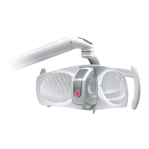
Faro ALYA User manual

GARANTIEZERTIFIKAT
FARO gewährt dem Endkunden eine Garantie von 24 Monaten ab dem Kaufsdatum.
Die Reparatur unter Garantie muss bei FARO durchgeführt werden; Transportspesen und –Risiken
gehen zu Lasten des Kunden.
Die Reparatur unter Garantie wird nur dann gewährt, wenn:
−Das Zertifikat vollständig ausgefüllt und per Fax im voraus an FARO geschickt wurde
(039.6010540).
Die Garantie gilt für Schäden, die durch Qualitätsmängel des Materials oder Herstellungsfehler
entstanden sind. Im Falle einer begründeten Reklamation bietet die Garantie die kostenfreie Reparatur
oder den Ersatz. Ausgeschlossen ist die Möglichkeit, Schadenersatz und/oder Zinsvergütungen
zu erhalten. Die Garantie wird nach unbestreitbarem Urteil von FARO als ungültig betrachtet, wenn
Änderungen, Beschädigungen, nicht fachgerechter Gebrauch, schlechte Wartung oder normaleAbnutzung
vorliegen.
CERTIFICADO DE GARANTIA
La firma FARO concede al cliente final una garantía de 24 meses a partir de la fecha de adquisición.
La reparación en garantía debe ser efectuada en la sede de FARO; los gastos y riesgos de transporte
están a cargo del comprador.
La reparación en garantía se considera válida sólo cuando:
−el certificado ha sido llenado en todas sus partes y enviado previamente a FARO vía Fax
(039.6010540).
La garantía cubre las averías debidas a defectos de calidad del material o defectos de fabricación;
en caso de reclamo fundado la garantía permite la reparación o sustitución gratuita. Se excluye la
posibilidad de obtener una indemnización por daños y/o intereses. La garantía no será considerada
válida, a exclusiva discreción de FARO, en el caso de alteración, daños, uso incorrecto, mantenimiento
inadecuado o desgaste normal.
DISPOSITIVO MEDICO
MEDICAL DEVICE
CERT. 9120.FAR1
CERT. 9124.FAR2
Azienda
Certificata
FARO S.p.A.
via Faro, 15 - 20876 Ornago (MB) - Italy
Tel. +39 039.68781 - Fax +39 039.6010540
www.faro.it - comm.italia@faro.it - comm.estero@faro.it
FARO FRANCE
Za Tgv Coriolis - 71210 Monchanin - France
Tel. +33 385.779680 - Fax +33 385.779688
www.farofrance.com - farofrance@farofrance.com
FARO DEUTSCHLAND GMBH
Gewerbepark Heideckhof Heideckstr. 179
D-47805 Krefeld - Germany
Tel. +49 2151.936921 - Fax +49 2151.936933
www.faro.it - info@faro-dental.de
FARO SpA si riserva il diritto di modificare, senza preavviso, le caratteristiche indicate nel presente manuale.
FARO SpA reserves the right to change the specifications of this equipment without notice.
FARO SpA se reserve le droit de modifier, sàns préavis, les caractéristiques dans ce manuel.
FARO SpA behält sich rechtvor, jederzeit stillschweigend technische oder bauliche Änderung worzunehmen.
FARO SpA se reserva el derecho de modificar sin aviso previo la caracteristicas incluidas en el presente manual de uso.
ALYA
MANUALE D’USO
INSTRUCTION MANUAL
MODE D’EMPLOI
GEBRAUCHSANLEITUNG
MANUAL DE USO
01
LAMPADA DENTALE A LED
DENTAL LED LIGHT
Dispositivo Medico conforme
alla direttiva 93/42/CE
FARO SPA Ornago (Italy)
L’ODONTOTECNOLOGIA
Lampada dentale ALYA
CERTIFICATO DI GARANZIA
GUARANTEE CERTIFICATE
CERTIFICAT DE GARANTIE
GARANTIEZERTIFIKAT
CERTIFICADO DE GARANTIA

CERTIFICATO DI GARANZIA
La Faro concede al cliente finale una garanzia di 24 mesi a partire dalla data di acquisto.
La riparazione in garanzia deve essere effettuata presso la FARO; spese e rischi di trasporto sono a rischio
dell’acquirente. La riparazione in garanzia è ritenuta valida solo quando:
- il certificato è stato compilato in tutte le sue parti e inviato anticipatamente alla FARO
tramite Fax ( 039.6010540).
La garanzia risponde dei guasti dovuti alla cattiva qualità del materiale o a difetti di fabbricazione, in
caso di fondato reclamo la garanzia consente la riparazione o la sostituzione gratuita. E’ esclusa la
possibilità di ottenere risarcimento di danni e/o di interessi. La garanzia non è ritenuta valida, a
insindacabilegiudizio della FARO, in caso di manomissione, danneggiamento, di scorretta utilizzazione,
di cattiva manutenzione o di normaleusura
GUARANTEE CERTIFICATE
FARO offers the final customer a 24 month guarantee starting from the date of purchase.
Repairs under guarantee must be performed at FARO; expenses and transport risks are at the risk of the
purchaser. Repair under guarantee is considered valid only when:
−all sections of the certificate have been filled in and sent in advance to FARO by Fax
(039.6010540).
The guarantee covers faults due to the bad quality of the material or manufacturing defects; in the case
of valid claims, the guarantee covers free repair or replacement. Claims for damages and/or interest
are excluded. The guarantee is not considered valid, at the sole discretion of FARO, if the fault is due
to tampering, damage, incorrect use, improper maintenance and normal wear and tear.
CERTIFICAT DE GARANTIE
FARO accorde au client final une garantie de 24 mois, à compter de la date de l’achat.
La réparation sous garantie peut être effectuée chez FARO; les frais et les risques de transport sont aux
risques de l’acheteur. La réparation sous garantie ne peut être valable que si:
−Le certificat a été rempli entièrement et envoyé auparavant à FARO par Fax (039.6010540).
La garantie est valable pour des pannes dues à la mauvaise qualité du matériau ou à des défauts de
fabrication, en cas de réclamation fondée la garantie permettra la réparation ou le remplacement gratuit.
La possibilité de dédommagements ou d’indemnisation d’intérêts est exclue. La garantie n’est pas
valable, selon les décisions sans appel de FARO, en cas de modification non autorisée, endommagement,
utilisation incorrecte, mauvais entretien ou usure normale.
24 mesi-months-mois-monaten-meses
nome-name-nom-vorname-nombre cognome-surname-prenom-nachname-apellido
indirizzo-address-adresse-auschrift-direccion città-town-ville-ort-ciudad
SN LD data d’acquisto-purchase date-date d’achat
einkaufdatum-fecha de compra
versione-version-version-modell-versión Timbro del rivenditore-Dealer’s stamp-Cachet d’achat
Stempel der Fachhändlers-Sello del revendedor
ALYA
ed. 2/11
rev. 6 .
988285
ed.05/12
rev. 6
cod. 988280

11
Lampada dentale ALYA
SIMBOLOGIE
INDICE
Italiano ............................... pag. 1
Inglese................................ page 11
Francese ............................. page 21
Tedesco .............................. Seite 31
Spagnolo ............................ pág. 41
PERICOLO
I paragra contrassegnati con questo simbolo, contengono istruzioni che
devono essere eseguite attentamente per evitare danni al dispositivo,
all’operatore ed eventualmente al paziente.
AVVERTENZE
Queste istruzioni avvisano che bisogna porre molta attenzione per evitare
situazioni che potrebbero danneggiare il dispositivo.
DIVIETO
Questa icona mette in evidenza cosa non si deve fare per evitare danni al
dispositivo.
SUGGERIMENTI
Con questa icona, viene fornita un’informazione che permette di usare il
dispositivo in modo più efcace.
Smaltire il dispositivo attenendosi alle norme per la raccolta differen-
ziata del materiale elttrico.
Apparecchio di classe II.
Consultare la documentazione annessa.
!

2
Lampada dentale ALYA
- La lampada dentale ALYA ha la funzione di illuminare la cavità orale del paziente
durante gli interventi di odontoiatria.
- La lampada deve essere utilizzata da personale qualicato.
L’installazione del dispositivo deve essere eseguita solo da personale specializzato.
Vericare che la tensione di alimentazione, indicata sulla targhetta dati, corrisponda
a quella di rete.
La lampada dentale deve essere installata su uno specico dispositivo di controllo
e di alimentazione, come riuniti dentali, o con impianto elettrico che soddisfa
la norma IEC 60364-1 e le “regole nazionali d’installazione per impianti elet-
trici in locali adibiti ad uso medico”.
L’apparecchio deve essere installato con un dispositivo di separazione dalla rete di
tipo onnipolare e conforme alla IEC 61058, occorre provvedere ad inserire
una spia di colore verde per indicare che la lampada è alimentata.
- Non effettuare alcun intervento di manutenzione sulla lampada quando l’alimen-
tazione è inserita; scollegare il cavo di alimentazione dalla rete prima di intervenire.
- Non introdurre nelle feritoie della testata della lampada, oggetti o attrezzi che
potrebbero toccare punti sotto tensione.
- Il braccio articolato e gli snodi della testata permettono il corretto posizionamento
del fascio luminoso. Non sovraccaricare i bracci e gli snodi con urti sui ne corsa.
- Non ssare il fascio luminoso per i pazienti a rischio (es. bambini con patologie
agli occhi). Utilizzare sempre opportune protezioni e precauzioni; Faro suggerisce
di utilizzare gli occhiali protettivi BLUE-BAN o BABY BLUE-BAN (per bambini).
- Non adatta ad essere installata in ambienti con presenza di gas infiammabili.
- Non spruzzare detergenti-disinfettanti direttamente sulla testata.
- Targhetta dati indicazioni led ssata sul braccio posteriore.
- L’inadeguatezza delle prestazioni del dispositivo non pregiudica in alcun modo la
sicurezza del paziente.
- Per la pulizia delle parti in plastica lampada ALYA NON UTILIZZARE
detergenti-disinfettanti contenenti: AMMONIUM HYDROXIDE - SODIUM
HYDROXIDE - METHYLENE CLORIDE - METHYL ALCOHOL.
Il mancato rispetto della prescrizione potrebbe causare: • rischio di rottura delle
parti plastiche • rischio di cedimento strutturale degli snodi, con possibile caduta
del braccio articolato. In caso di dubbio contattare Customer Care Faro.
- Non eseguire operazioni di manutenzione o di sostituzioni di parti diverse da
quelle riportate nel manuale. Qualsiasi intervento non indicato nello stesso potrebbe
compromettere l’aspetto sicurezza previsto dal dispositivo.
- Per la disinfezione delle superci usare disinfettanti idroalcolici.
- Non lasciare piccoli componenti dell’apparecchiatura incustoditi o alla portata di
persone esposte (bambini) perchè potenziali fonti di pericolo.
- Il medico è tenuto ad utilizzare le protezioni monouso sulle maniglie della lam-
pada o a garantirne la sterilizzazione nelle versioni che ne prevedano la possibilità.
- Dividere i materiali in base alla loro tipologia (es. ferrosi, gomma, plastica etc.).
Per la rottamazione e lo smaltimento dei materiali attenersi alla normativa vigente nel
proprio paese, ricorrendo eventualmente a ditte specializzate riconosciute e autorizzate.
- L’imballo della lampada è adatto a proteggere adeguatamente la stessa dalla pene-
trazione di agenti esterni.
- L’apparecchio nell’imballo originale può essere trasportato o tenuto in magazzi-
no per un periodo di 15 settimane se vengono rispettate le seguenti condizioni
ambientali:
-Temperatura ambiente da –20° C a + 70°C
- Umidità relativa dal 10% al 90%
- Pressione atmosferica da 500 a 1060 mBar
- L’apparecchio deve essere utilizzato alle seguenti condizioni ambientali:
-Temperatura da 10° a 40°C
-Umidità relativa da 30 a 75%
-Pressione atmosferica da 700 a 1060mbar
NORME DI SICUREZZA

33
Lampada dentale ALYA
NORME DI SICUREZZA
IMMUNITA’ ELETTROMAGNETICA
Guida e dichiarazione del costruttore - Immunità elettromagnetica
La lampada ALYA è prevista per funzionare nell’ambiente elettromagnetico sotto specicato. Il cliente o l’utilizzatore dovrebbero
assicurarsi che esso venga usato in tale ambiente
Prova di Immunità Conformità Ambiente Elettromagnetico - Guida
Electrostatic discharge (ESD)
IEC/EN61000-4-2
± 6kV contact
± 8kV air
I pavimenti devono essere in legno, calcestruzzo o in ceramica.
Se i pavimenti sono ricoperti di materiale sintetico, l’umidità
relativa dovrebbe essere almeno al 30%.
La qualità della tensione di rete dovrebbe essere quella di un
tipico ambiente commerciale o ospedaliero.
La qualità della tensuione di rete dovrebbe essere quella di un
tipico ambiente commerciale o ospedaliero.
La qualità della tensione di rete dovrebbe essere quella di un
tipico ambiente commerciale o ospedaliero. Se l’utilizzatore
della lampada ALYA richiede unn uso continuativo anche in
assenza della tensione di rete si raccomanda l’uso di un gruppo
di continuità.
Livello di campo magnetico alla frequenza di rete tipico di un
ambiente commerciale e ospedaliero.
Electrical fast transient/burst
IEC/EN61000-4-4
Surge
IEC/EN61000-4-5
Voltage dips, short interruption
and voltage variation
IEC/EN61000-4-11
Power frequency magnetic eld
IEC/EN61000-4-8
± 2kV power supply
± 1kV for input/output lines
± 1kV differential mode
± 2kV common mode
< 5% Ut for 0,5 cycle
40% Ut for 05 cycle
70% Ut for 25 cycle
<5% Ut for 5 sec.
3A/m
Immunità Condotte
IEC/EN61000-4-6
Immunità Condotte
IEC/EN61000-4-6
3Vrms 150kHz to 80MHz
(per apparecchi che non sono
life-supporting)
3Vrms 80MHz to 2.5GHz
(per apparecchi che non sono
life-equipment)
Gli apparecchi di comunicazione a RF portatili e mobili non
dovrebbero essere usati vicino a nessuna parte dell’unità den-
tale, compresi i cavi, eccetto quando rispettano le distanze di
separazione raccomandate calcolate dall’equazione applicabile
alla frequenza del trasmettitore.
Distanze di separazione raccomandate:
d = 1,2√P
d = 1,2√P da 80 Mhz a 800 MHz
d = 2,3√P da 800 MHz a 2,5 GHz
Dove P è la potenza massima nominale d’uscita del trasmettitore
in Watt (W) secondo il costruttore del trasmettitore e d é la di-
stamza di separazione raccomandata in metri (m).
L’intensità del campo dei trasmettitori a RF ssi, come deter-
minato in un’indagine elettromagnetica del sito a, potrebbe
essere minore del livello di conformità di ciascun intervallo di
frequenza.
Si può vericare interferenza in prossimità di apparecchi con-
trassegnati dal seguente simbolo:
Nota: Ut è il valore della tensione di alimentazione
Nota 1: A 80 MHz e 800 Mhz si applica l’intervallo della frequenza più alta.
Nota 2: Queste linee guida potrebbero non applicarsi in tutte le situazioni. La propagazione elettromagnetica è inuenzata dall’assor-
bimento e dalla riessione di strutture, oggetti e persone.
a) Le bande ISN (industriali, scientiche e medicali) tra i 150kHz e 80MHz sono 6,765 MHz a 6,795MHz; 13,553 MHz a 13,567
MHz; 26,957 MHz a 27,283 MHz e 40,66 MHz a 40,70 MHz.
b) I livelli di conformità nelle bande ISN tra 150kHz e 80MHz e nelle bande 80MHz a 2,5GHz sono intesi a decrescere in probabilità
che un dispositivo di trasmissione portatile può causare interferenza se inavvertitamente portato nell’area paziente.
Per questa ragione, un fattore addizionale di 10/3 è stato incorporato nella formula usata nel calcolo della distanza di separazione
dai trasmettitori.
c) Le intensità di campo per trasmettitori ssi come le stazioni di base per radiotelefoni (cellulari e cordless) e radiomobili terrestri,
apparecchi di radioamatori, trasmettitori radio in AM e FM e trasmettitori TV non possono essere previste teoreticamente e con
precisione. Per stabilire un ambiente elettromagnetico causato da trasmettitori RF ssi, si dovrebbe considerare un’indagine elettro-
magnetica del sito. Se l’intensità di campo misurata nel luogo in cui si usa l’unità dentale supera il livello di conformità applicabile di
cui sopra, si dovrebbe porre sotto osservazione il funzionamento normale della lampada. Se si notano prestazioni anormali, possono
essere necessarie misure aggiuntive come un diverso orientamento o posizione della lampada.
d) L’intensità di campo su un intervallo di frequenze da 150 kHz a 80 MHz dovrebbe essere minore di 3 V/m.
Conformità Ambiente Elettromagnetico - Guida
Group 1 La lampada ALYA utilizza energia RF solo per il funzionamento interno.
Perciò le sue emissioni RF sono molto basse e verosimilmente non cau-
sano nessuna interferenza negli apparecchi elettronici vicini.
Class B
Class C La lampada ALYA è adatta per l’utilizzo in tutti gli edici, inclusi quelli
domestici e quelli direttamente collegati alla rete di alimentazione pub-
blica in bassa tensione che alimenta edici per domestici.
REQUISITI PER LA COMPATIBILITA’ ELETTROMAGNETICA
Il dispositivo medico necessita di particolari precauzioni per quanto concerne la compatibilità elettromagnetica e deve essere
installatio e utilizzato secondo le informazioni fornite con i documenti di accompagnamento.
Guida e dichiarazione del costruttore - Emissioni elettromagnetiche
La lampada ALYA è prevista per funzionare nell’ambiente elettromagnetico sotto specicato. Il cliente o l’utilizzatore dovrebbero
assicurarsi che esso venga usato in tale ambiente
Prova di Emissione
RF Emission
CISPR11 / EN 55011
RF Emission CISPR11 / EN 55011
Harmonic emission EN/IEC 61000-3-2
Voltage uctuations/icker emission
EN/IEC 61000-3-3 Conforme
RF Emission
CISPR11 / EN 55011 Conforme La lampada ALYA non è adatta per essere interconnessa con altri dispo-
sitivi (versione da softto).

4
Lampada dentale ALYA
Distanze di separazione raccomandate tra apparecchi di radiocomunicazione
portatili e mobili e l’unità dentale
La lampada ALYA è prevista per funzionare in un ambiente elettromagnetico in cui sono sotto controllo i disturbi irradiati RF. Il
cliente o l’operatore dell’unità possono contribuire a prevenire interferenze elettromagnetiche assicurando una distanza minima fra
apparecchi di comunicazione mobili e portatili a RF (trasmettitori) e l’unità dentale, come sotto raccomandato, in relazione alla
potenza di uscita massima degli apparecchi di radiocomunicazione.
Potenza di uscita
nominale massima del
trasmettitore
W
Distanza di separazione alla frequenza del trasmettitore
m
0,01
0,1
1
10
100
150 kHz a 80 MHz
d = 1,2 √P
Per i trasmettitori con potenza nominale massima di uscita sopra non riportata, la distanza di separazione raccomandata d in metri
(m) puà essere calcolata usando l’equazione applicabile alla frequenza del trasmettitore, ove P è la potenza masima nominale d’uscita
del trasmettitore in Watt (W) secondo il costruttore del trasmettitore.
Note:
A 80 MHz e 800 MHz si applica l’intervallo della frequenza più alta.
Queste linee guida potrebbero non applicarsi inn tutte le situazioni. La propagazione elettromagnetica è inuenzata dall’assorbimen-
to e dalla riessione di strutture, oggetti e persone.
80 MHz a 800 MHz
d = 1,2 √P 800 MHz a 2,5 GHz
d = 2,3 √P
0,12
0,38
1,2
3,8
12
0,12
0,38
1,2
3,8
12
0,23
0,73
2,3
7,3
23

55
Lampada dentale ALYA
CARATTERISTICHE
Versioni
La lampada dentale “ALYA” viene fornita nelle versioni:
- Lampada S/TS (con/senza trasformatore) con joystick
- Lampada S/TS (con/senza trasformatore) con interruttore a faretra (on/off)
- Lampada S/TS (con/senza trasformatore) con proximity
- Lampada S/TS (con/senza trasformatore) versione a softto con joystick o proximity
- Sorgente luminosa costituita da due LED la cui luce si riette su due parabole passando
per 2 lenti secondarie.
- Supercie riettente con parabole che permetteno di ottenere uno spot di luce regolare
ed uniforme ad ogni livello d’illuminamento e di distribuire uniformemente la luce
nel campo operativo, senza creare ombre od oscuramenti da parte dell’operatore.
- Regolazione dell’intensità luminosa con un joystick o con proximity.
- Proximity permette di accendere o spegnere la lampada senza avere un contatto diretto,
eliminando così la possibilità di infezioni incrociate.
- Manutenzione facilitata grazie all’applicazione di nuove tecnologie che tengono in
considerazione le varie esigenze in fatto di sicurezza, ergonomia e igiene.
- Maniglie staccabili permette la sterilizzazione.
1
1 - Joystick
2 - Lente
3 - Parabola
4 - Maniglia
5 - Proximity
6 - Fusibili
7 - Trasformatore
6
7
DESCRIZIONI DELLE PARTI
2 3 4
5

6
Lampada dentale ALYA
INSTALLAZIONE e COLLEGAMENTI
Lampada dentale “ALYA” versione S/TS
Vericare che nella confezione siano contenuti i seguenti componenti:
- Lampada dentale (nella versione richiesta)
- Busta levetta + chiave
- Manuale d’istruzione
Il dispositivo deve essere pulito prima dell’utilizzo
(vedi paragrafo Pulizia del dispositivo).
Il dispositivo deve essere installato da tecnici specializzati.
L’alimentazione, all’atto dell’installazione, deve sempre essere disinserita.
L’uso contemporaneo della lampada con un elettrobisturi può provocare
malfunzionamenti della stessa. Per ridurre i rischi, si consiglia la versione
con controllo tramite jostick, anziché quella con il sensore di prossimità.
Vericare sempre prima dell’uso.
Montaggio lampada versione a riunito
- Installare la lampada inserendo il perno terminale lampada nell’apposito foro del riunito.
1) CAVO DI ALIMENTAZIONE:
- LAMPADA CON TRASFORMATORE; deve essere alimentata direttamente dalla
tensione di rete corrispondente alle caratteristiche riportate sulla targhetta dati o nelle
speciche tecniche del manuale.
- Assicurarsi che l’interruttore di linea sia conforme alla norma IEC 61058.
- LAMPADA SENZA TRASFORMATORE; deve essere alimentata da corrente alter-
nata a bassa tensione (17 - 24V AC) utilizzando un trasformatore di sicurezza conforme alla
EN 60601-1.
2) CAVO DI CONTROLLO REMOTO (dove presente):
- collegare il cavo a due pulsanti, con contatto normalmente aperto (non forniti), secondo
lo schema seguente:
Carico totale Carico in sicurezza
(SAFE WORKING LOAD)
(MINIMUM BREAKING LOAD)
Braccio lung. 855 mm 3.12 Kg 26 Kg.
Braccio lung. 550 mm 2.64 Kg 35 Kg
progeCAD 2008 Smart! - Private use only
A B

77
Lampada dentale ALYA
ISTRUZIONI D’USO
SIMBOLO INTERRUTTORI
LAMPADA “ALYA” CON JOYSTICK
(vedi descrizione delle parti)
Accensione / Spegnimento / Regolazione
- Per l’accensione e lo spegnimento premere e rilasciare la leva joystick agendo sul lato
sinistro o destro.
- Regolazione:
a) per ridurre l’intensità luminosa mantenere premuta la leva del joystick agendo sul lato sini-
stro (vista posteriore lampada) no al raggiungimento dell’intensità desiderata.
Al raggiungimento della minima intensità sarà udibile una segnalazione acustica (1 beep).
b) per aumentare l’intensità luminosa mantenere premuta la leva del joystick agendo sul lato
destro (vista posteriore lampada) no al raggiungimento dell’intensità desiderata.
Al raggiungimento della massima intensità sarà udibile una segnalazione acustica (1 beep).
Il joystick di controllo deve essere maneggiato con delicatezza onde evitare rotture.
Ogni volta che si accende la lampada, l’intensità luminosa sarà quella memoriz-
zata al precedente spegnimento.
LAMPADA “ALYA” CON PROXIMITY (vedi descrizione delle parti)
Accensione / Spegnimento
- Per l’accensione o spegnimento avvicinarsi una volta al sensore sino ad una distanza
massima di 3 cm.
- Per la regolazione dell’intensità luminosa bisogna restare fermi in prossimità del sensore
sino ad ottenere l’intensita desiderata, dal valore massimo al minimo e dal valore minimo
ancora al massimo. Al raggiungimento della massima intensità sarà udibile una segnalazione
acustica (2 beep). Al raggiungimento della minima intensità sarà udibile una segnalazione
acustica (1 beep).
Ogni volta che si accende la lampada, l’intensità luminosa sarà quella memoriz-
zata al precedente spegnimento.
LAMPADA “ALYA” CON COMANDO REMOTO (vedi descrizione delle parti)
Accensione / Spegnimento / Regolazione
- Per l’accensione e lo spegnimento premere e rilasciare il pulsante “A”.
- Regolazione:
a) per ridurre l’intensità luminosa mantenere premuto il pulsante “A” no al raggiun-
gimento dell’intensità desiderata.
Al raggiungimento della minima intensità sarà udibile una segnalazione acustica (1 beep).
b) per aumentare l’intensità luminosa mantenere premuto il pulsante “A” no al raggiun-
gimento dell’intensità desiderata.
Al raggiungimento della massima intensità sarà udibile una segnalazione acustica (2 beep).
c) per raggiungere immediatamente la minima intensità luminosa premere il pulsante “B”.
Al raggiungimento della minima intensità sarà udibile una segnalazione acustica (1 beep).
Una successiva pressione del pulsante riporterà la lampada all’intensità luminosa prece-
dentemente selezionata.
Ogni volta che si accende la lampada, l’intensità luminosa sarà quella memoriz-
zata al precedente spegnimento.
ON-OFF

8
Lampada dentale ALYA
PULIZIA DELLE PARABOLE “3” (vedi descrizione delle parti):
Faro consiglia per la pulizia l’utilizzo del detergente “Faro Perex”; in alternativa la pulizia
deve essere effettuata utilizzando panno morbido e alcool isopropilico. Non usare deter-
genti contenenti tensioattivi o idrorepellenti che depositandosi possono lasciare alonature.
Per la disinfezione sono idonei disinfettanti idroalcolici con 70% di alcool
isopropilico o etilico.
Per la pulizia delle parti in plastica lampada ALYA NON UTILIZZARE
detergenti-disinfettanti contenenti: AMMONIUM HYDROXIDE - SODIUM
HYDROXIDE - METHYLENE CLORIDE - ME THYLALCOHOL.
Faro ha testato e suggerisce i seguenti disinfettanti: •Eco Jet-1 (Cattani Group)
•Sporekin Plus DS (Ims srl) • Zerol Quick (Molteni Dental).
Dopo la disinfezione si consiglia l’utilizzo del prodotto “Faro Perex” per la
riomozione di residui ed aloni.
ATTENZIONE: prodotti differenti potrebbero danneggiare i riettori (para-
bole). In caso di dubbio contattare il customer care FARO.
Lievi alonature non pregiudicano la qualità della luce.
STERILIZZAZIONE MANIGLIA
Per rimuovere la maniglia svitare il pulsante “A” e slarla. Per
inserirla è sufciente spingerla in battuta ed avvitare “A”.
Le maniglie non sono fornite sterili, devono quindi essere
sterilizzate prima dell’utilizzo.
Maniglie sterilizzabili con cicli standard 121°/134° C per
un massimo di duecento (200) sterilizzazioni.
ALTRE PARTI DELLA LAMPADA (testata-braccio articolato)
La pulizia deve essere effettuata con un panno morbido.
Per tutte le parti della lampada è tassativamente proibito l’impiego di sostanze
abrasive, detergenti a base di trielina, benzina, acquaragia o similari.
Eseguire periodicamente le prove di sicurezza elettrica previste per le appa-
recchiature installate nei locali medici.
“A”
MONTAGGIO LEVETTA JOYSTICK ALYA
- Inserire in battuta la levetta “A”sul perno del joystick.
- Il foro della levetta “A”deve essere posizionato in corrispondenza
del piano “B”.
- Avvitare completamente il grano “C” con la brugola in dotazione.
Il joystick di controllo deve essere maneggiato con
delicatezza onde evitare rotture.
Sostituzione dei fusibili “6” nella versione con trasformatore (vedi descrizione delle parti)
La lampada con trasformatore è corredata di due fusibili dello stesso valore.
Per la sostituzione procedere nel seguente modo:
- Accertarsi che l’alimentazione non sia inserita.
- Svitare i tappi “6” posti sul porta trasformatore.
- Estrarre i fusibili. Dopo aver constatato l’interruzione, sostituire il fusibile.
E’ importante che i nuovi fusibili abbiano le caratteristiche indicate sulla
targhetta dati e nelle speciche tecniche.
MANUTENZIONE/PULIZIA
B
A
C

99
Lampada dentale ALYA
VERIFICHE PERIODICHE
Vericare assenza di gioco tra gli snodi dei bracci (annuale)
Verica leggibilità dati di targa (annuale)
Veriche di sicurezza elettrica: (Biennale)
1. Rigidità
2. Dispersione.
Veriche luce: (quinquennale o 10.000 ore di funzionamento)
1. Illuminamento massimo: >35000 lux.
2. Decadimento del CRI: <20% rispetto ai dati di targa.
3. Valore sotteso della luce Blu sullo spettro emesso misurato in w/m2: <100
INSTALLAZIONE APPLICAZIONE SOFFITTO
Prima di procedere con il montaggio della lampada, ad una struttura (es. softto), vericare
il carico complessivo del sistema da installare, dato dal peso del sistema più il carico mas-
simo applicabile alla lampada. Accertarsi quindi che la struttura e gli elementi di ssaggio
selezionati siano adeguati per sopportare il carico risultante, moltiplicato per un fattore di
sicurezza di K8.
Accertarsi inoltre che gli elementi di ssaggio siano adeguati al materiale del softto (es.
calcestruzzo, pietra, mattone pieno, mattone forato).
Per l’ utilizzo di un’applicazione a softto FARO predisposta per 2 lampade, il carico si
calcola come segue:
- Lampada Alya senza trasformatore completa di braccio e snodo: 6kg
- Colonna per ssaggio a softto lunghezza 1700 mm: 8 kg
- Plafoniera per applicazione a softto con 2 trasformatori
per l’applicazione di 2 lampade: 8 kg
- Carico applicabile alla lampada: 35 kg
- Carico Totale per 2 lampade: 6X2 + 8 + 8 + 35X2 = 98 kg
Carico con coefciente di sicurezza 8: 98 kg X 8 = 784 kg ( 7,7 kN)
IN DOTAZIONE
N° 5 - Tasselli ad espansione (adatti per calcestruzzo e pietra naturale)

10
Lampada dentale ALYA
SPECIFICHE TECNICHE
SEGNALI ACUSTICI DI ALLARME
La lampada non si accende - Vericare che l’alimentazione sia inserita.
- Controllare lo stato dei fusibili.
- Se nessuna di questa cause si fosse vericata, consultare
l’assistenza tecnica.
L’intensità luminosa si è - Pulire le parabole.
notevolmente ridotta Nel caso l’intensità luminosa non ritornasse ai valori
iniziali, consultare l’assistenza tecnica.
Le maniglie non si agganciano
- Eseguire ciclo di sterilizzazione a 121°/134° con
o si sganciano a fatica apposito conformatore PN 310136
Sui riettori (parabole) - Pulire le superci con lo specico prodotto “Faro Reex”.
sono comparse delle macchie - Pulire le superci con alcool isopropilico.
- E’ stato utilizzato un prodotto per la pulizia o la disinfe-
zione non idoneo che ha danneggiato la supercie.
- Contattare il customer care FARO.
Tensione alimentazione (senza trasformatore) : 17÷24V ac ± 10% -50/ 60 Hz
22÷35V dc
Tensione alimentazione (con trasformatore) : 230 V 50 / 60 Hz
Potenza assorbita : 26VA
Fusibili (versione con trasformatore) : 2 x T250mAL 250V
Protezione contro i pericoli elettrici : Apparecchio di classe II
CARATTERISTICHE OTTICHE IN ACCORDO ALLA ISO 9680
Dimensioni spot luminoso : 180 mm x 90 mm
Lux : 3000*-50000* lux @700mm
Temperatura di colore : 5000 K
CRI (color rendering index) : >95*
* Valore tipico
Etichettatura conforme alla EN 60825-1:94+A1:02+A2:01
GUIDA AI PROBLEMI
OTP* = Beep 30 secondi
MAX = 1 beep - 2 beep con prox.
MIN = 1 beep
1 BEEP = Ai comandi
1 BEEP = All’accensione
OpL** = Beep 30 secondi
* OTP: Protezione sovratemperatura
** OpL: Carico led scollegato

1111
Lampada dentale ALYA
SYMBOLS
DANGER
The paragraphs marked with this symbol contain instructions that must be
carried out carefully to prevent damage to the system, the operator, and
possibly the patient.
WARNING
These instructions advise that great care must be taken to avoid situations
that could damage the system.
PROHIBITION
This icon highlights what should not be done in order to prevent damaging
the device.
SUGGESTIONS
With this icon, information is provided that enables the system to be used
more efciently.
Dispose of the system in accordance with regulations for the separate col-
lection of electrical material.
Device classe II
Consult the enclosed documentation.
!

12
Lampada dentale ALYA
SAFETY REGULATIONS
- The function of the ALYA dental light is to illuminate the oral cavity of the
patient during dental operations.
- The light must be used by qualied staff.
- The articulated arm and head joint ensure that the light beam is correctly posi-
tioned. Do not overload the arms and joints with impact on the limit switches.
- Installation of the system must only be performed by specialized staff.
- Check that the power voltage, shown on the data plate, corresponds to the mains
voltage.
- Do not block the light beam for patients at risk (i.e. with eye conditions). Use
correct protection and precautions.
- Information plate with LED indications xed to the rear arm.
- The dental light must be installed on a specic control and supply device, such
as a dental unit, or with an electrical system that complies with standard
IEC 364-1 and “national regulations for installation of electrical systems in
areas for medical use”.
- The device must be installed with an omnipolar shut-off switch that disconnects
it from the mains and is conformant to IEC/EN 61058. It is necessary to install
a green signal light to indicate when the lamp is switched on.
- Do not carry out any maintenance work when the power is on; disconnect the
power cable from the mains beforehand.
- Do not introduce items or tools into slits in the light head that could touch live points.
- Patients at risk (e.g. children with eye diseases) must not stare at the light beam.
Always use appropriate protection devices and precautions. Faro suggests using
the protective eyeware BLUE-BAN or BABY BLUE-BAN (for children).
- Not suitable for installation in environments containing ammable gas.
- Do not spray detergents-disinfectants directly on the head.
- Inadequate performance of the system does not in any way compromise the
safety of the patient.
- For cleaning plastic parts of the lamp ALYA, DO NOT USE detergents-
disinfectants containing: AMMONIUM HYDRIXIDE – SODIUM
HYDROXIDE – METHYLENE CHLORIDE – METHYL ALCOHOL. Failure
to comply with this indication might cause: • risk of breakage of plastic
parts • risk of structural breakdown of joints with potential fall of the articulated
arm. In case of doubt, please contact CUSTOMER CARE FARO.
- Do not carry out maintenance or replacement work on parts other than those
shown in the manual. Any operation not indicated in the manual could compro-
mise the safety aspect of the device.
- Disinfect surfaces with hydroalcoholic disinfectants.
- Do not leave small parts unattended or within the reach of exposed persons
(children); they could be potential sources of danger.
- The dentist is obliged to used the disposal protection sleeves on the handles of
the lamp or ensure that versions without this possibility are sterilized.
- Divide materials according to their type (e.g. iron, rubber, plastic.). When scra-
ping and disposing of the materials, comply with the current legislation of your
country, and if necessary use recognized and authorized specialist companies.
- The packaging of the light is suitable for protecting it from the penetration of
external agents.
- The system in its original packaging can be transported or kept in storage for a
period of 15 weeks if the following environmental conditions are observed:
- Ambient temperature from –20° C to + 70°C
- Relative humidity from 10% to 90%
- Atmospheric pressure from 500 to 1060 mBar
- The system must be used in the following environmental conditions:
- Temperature from 10° to 40°C
- Relative humidity from 30 to 75%
- Atmospheric pressure from 700 to 1060 mBar

1313
Lampada dentale ALYA
SAFETY REGULATIONS
ELECTROMAGNETIC IMMUNITY
Manufacturer’s guide and declaration – Electromagnetic immunity
The ALYA lamp is made to function in the electromagnetic environment specied below. The client or user should make sure that it is
effectively used in this environment.
Immunity test Conformity Guide – Electromagnetic environment
Electrostatic discharge (ESD)
IEC/EN61000-4-2
± 6kV contact
± 8kV air
Flooring must be in wood, concrete or ceramic tile. If oors are
covered with synthetic material, the relative humidity should be
at least 30%.
The quality of network voltage should be equivalent to that of a
typical commercial or hospital environment.
The quality of network voltage should be equivalent to that of a
typical commercial or hospital environment.
The quality of network voltage should be equivalent to that of
a typical commercial or hospital environment. If the user of the
ALYA lamp requires continuative use, also when electrical po-
wer is not present, it is advisable to have a UPS (uninterrupted
power supply).
Level of the magnetic eld at the typical power main frequency
of a commercial or hospital environment.
Electrical fast transient/burst
IEC/EN61000-4-4
Surge
IEC/EN61000-4-5
Voltage dips, short interruption
and voltage variation
IEC/EN61000-4-11
Power frequency magnetic eld
IEC/EN61000-4-8
± 2kV power supply
± 1kV for input/output lines
± 1kV differential mode
± 2kV common mode
< 5% Ut for 0,5 cycle
40% Ut for 05 cycle
70% Ut for 25 cycle
<5% Ut for 5 sec.
3A/m
Conducted immunity
IEC/EN61000-4-6
Conducted immunity
IEC/EN61000-4-6
3Vrms 150kHz to 80MHz
(for non life-supporting
equipment)
3Vrms 80MHz to 2.5GHz
(for non life-supporting
equipment)
Portable and mobile RF communication devices should not be
used near any part of the dental unit, including cables, except
for when they comply with the recommended separation di-
stances calculated by the equation applicable for the transmitter
frequency.
Recommended separation distances:
d = 1,2√P
d = 1,2√P from 80 Mhz to 800 MHz
d = 2,3√P from 800 MHz to 2,5 GHz
Where P is the maximum nominal power emitted from the tran-
smitter in Watts (W), according to the transmitter manufacturer,
and d is the recommended separation distance in metres (m).
The intensity of the xed RF transmitter eld, as determined
in an electromagnetic study of the site a, could be less than the
level of conformity of each frequency interval.
Interference could be experienced in proximity to devices bea-
ring the following symbol:
Note: Ut is the value of the voltage.
Note 1: At 80 MHz and 800 Mhz the higher frequency interval is applied.
Note 2: These guidelines may not apply in all situations. Electromagnetic propagation is inuenced by the absorption and reection
of structures, objects and people.
a) The ISM bands (industrial, scientic and medical) between 150 kHz and 80 MHz are 6.765 MHz to 6.795 MHz; 13.553 MHz to
13.567 MHz; 26.957 MHz to 27.283 MHz and 40.66 MHz to 40.70 MHz.
b) The levels of conformity of the ISM bands between 150 kHz and 80 MHz and in the bands 80 MHz to 2.5 GHz are indicative.
The probability of a portable transmitter causing interference if accidentally brought in the range of a patient decreases depending
on environment conditions. This is why an additional factor of 10/3 has been incorporated into the formula used to calculate the
separation distance from transmitters.
c) Field intensities for xed transmitters like base stations for radio-telephones (cellular and cordless phones) and terrestrial tran-
smitters, amateur radio stations, AM and FM radio transmitters and TV transmitters cannot be predicted theoretically and precisely.
To establish an electromagnetic environment caused by xed RF transmitters, an electromagnetic investigation of the site should be
done. If the intensity of the eld measured in the area of use of the dental unit is higher than the applicable level of conformity de-
scribed above, it is necessary to monitor the lamp to check that it functions properly. If abnormal performance is detected, additional
measures could prove necessary, such as a different orientation or position of the lamp.
d) The eld intensity in an interval of frequencies from 150 kHz to 80 MHz should be less than 3 V/m.
Conformity Guide – Electromagnetic environment
Yes The ALYA lamp uses RF energy only for internal functioning.
Therefore, its RF emissions are very low and probably do not
cause any interference with other nearby electronic equipment.
Yes
Class C
The ALYA lamp is suitable for use in all buildings, including do-
mestic buildings and those connected directly to the low voltage
public electricity mains that power domestic buildings.
REQUIREMENTS FOR ELECTROMAGNETIC COMPATIBILITY
This medical device requires particular precautionary measures to ensure electromagnetic compatibility, and must be installed and
used in compliance with the information provided in the accompanying documentation.
Manufacturer’s guide and declaration – Electromagnetic emissions
The ALYA lamp is made to function in the electromagnetic environment specied below. The client or user should make sure that it is
effectively used in this environment.
Emission tests
RF Emission CISPR15
RF Emission CISPR15
Harmonic emission
Yes The ALYA lamp is not suitable for interconnections with other
devices (ceiling model).
RF Emission
CISPR11 / EN 55011

14
Lampada dentale ALYA
Recommended separation distances between portable and mobile
radio-communication devices and the dental unit
The ALYA lamp is designed to function in an electromagnetic environment in which disturbances from RF emissions are kept under
control. The client or operator of the unit can contribute to preventing electromagnetic interference by assuring a minimum distance
between mobile and portable RF communication devices (transmitters) and the dental unit, as recommended below, in relation to the
maximum output power of the radio-communication devices.
Maximum
nominal output power
of the transmitter
W
Separation distance at the transmitter frequency
m
0,01
0,1
1
10
100
150 kHz to 80 MHz
d = 1,2 √P
For transmitters with a maximum nominal power emission not listed above, the recommended separation distance d in metres (m)
can be calculated using the equation applied to the transmitter frequency, where P is the maximum nominal power emission of the
transmitter in Watts (W) according to the manufacturer.
Note:
At 80 MHz and 800 MHz, the highest interval is applied.
These guidelines may not apply in all situations. Electromagnetic propagation is inuenced by the absorption and reection of
structures, objects and people.
80 MHz to 800 MHz
d = 1,2 √P 800 MHz to 2,5 GHz
d = 2,3 √P
0,12
0,38
1,2
3,8
12
0,12
0,38
1,2
3,8
12
0,23
0,73
2,3
7,3
23

1515
Lampada dentale ALYA
FEATURES
Versions
The “ALYA” dental light is supplied in the following versions:
- S/TS Light (with/without transformer) with joystick
- S/TS Light (with/without transformer) with switch at the table keyboard
- S/TS Light (with/without transformer) with proximity sensor
- S/TS Light (with/without transformer) with ceiling mounted version with joystick or
proximity sensor
- Light source formed by two LEDs whose light is mirrored on two dishes, passing through
2 secondary lenses.
- Reecting surfaces with dishes that allow to obtain a spot of regular uniform light at all
lighting levels and to uniformly distribute the light in the operating eld without the
operator creating shadows or dark areas.
- Light intensity adjustment using a mechanical switch or with a sensor.
- Infra-red sensor enables light to be switched on or off without direct contact, thereby
eliminating the possibility of cross-infection.
- Easy maintenance thanks to the application of new technology that takes into conside-
ration various requirement in terms of safety, ergonomics and hygiene.
- Removable handles for sterilization purposes.
1 - Joystick
2 - Lens
3 - Parabola
4 - Handle
5 - Proximity
sensor
6 - Fuses
6
7
DESCRIPTION OF PARTS
2 3 4
1
5

16
Lampada dentale ALYA
progeCAD 2008 Smart! - Private use only
INSTALLATION ANd CONNECTIONS
“ALYA” Dental Light, version S/TS
Check that the package contains the following components:
- Dental light (in the version requested)
- Lever envelope + tool
- Instruction manual
The system must be cleaned before use.
(see the paragraph Cleaning the device)
The system must be installed by specialized technicians.
The power must always be off when the system is installed.
Simultaneous use of the lamp with an electric scalpel can cause the scalpel
to malfunction. To reduce risks, it is advisable to use the version controlled
with the joystick instead of the proximity sensor. Always verify compatibility
before use.
Lamp assembly, combined version
- Install the lamp by inserting the terminal lamp pin into the specic hole on the combined unit.
1) POWER CABLE:
- LIGHT WITH TRANSFORMER; must be powered directly from the mains, which
should correspond to the specications indicated on the data plate or in the technical spe-
cications of the manual.
- Ensure that the line switch conforms to the surface distances in air as specied in Interna-
tional Publication IEC 328.
- LIGHTWITHOUTTRANSFORMER; must be powered with low-voltage alternating
current (24V AC) using a safety transformer that conforms to EN 60601-1.
2) REMOTE CONTROL CABLE (where available):
- Connect the cable with two push-buttons (not supplied), whose contact is normally open,
according to the following scheme:
SAFE WORKING LOAD MINIMUM BREAKING LOAD
Arm length 855 mm 3.12 Kg 26 Kg.
Arm length 550 mm 2.64 Kg 35 Kg
A B

1717
Lampada dentale ALYA
INSTRUCTIONS FOR USE
SWITCHES SYMBOL
“ALYA” LIGHT WITH JOYSTICK
(see the description of parts)
Turning on and off/ Adjustments:
- To turn the lamp on and off, press and release the joystick lever to the left or right side.
- Adjustment:
a) to reduce light intensity, keep the joystick lever pressed to the left side (rear view of
lamp) until it reaches the desired intensity. When it reaches the minimum intensity, the
machine will beep once.
b) to raise the light intensity, keep the joystick lever pressed to the right side (rear view
of the lamp) until it reaches the desired intensity. When it reaches the maximum inten-
sity, the machine will beep twice.
The control joystick must be handled delicately to prevent breakage.
Each time the lamp is turned on, the light intensity will be at the level memorised
when it was turned off the time before.
“ALYA” LIGHT WITH PROXIMITY SENSOR
(see the description of parts)
Turning on and off:
- To switch on and off, move near to the sensor up to a maximum distance of 3 cm
- For light intensity regulation, place the hand near the sensor until desired intensity is
reached, from the maximum to the minimum level and from the minimum to the maximum
level. On reaching maximum intensity, an acoustic signal will be heard (2 beeps); there
will be 1 beep for minimum intensity.
Each time the lamp is turned on, the light intensity will be at the level memorised
when it was turned off the time before.
“ALYA” DENTAL LIGHT SYSTEM WITH REMOTE CONTROL
(see the description of parts)
Turning on and off/ Adjustments:
- To switch on/switch off the lamp, press the push-button “A”.
- Adjustment:
a) To reduce the light intensity keep the push-button “A” pressed, until the desired inten-
sity is obtained.
When the minimum light intensity is obtained, you will hear an acoustic signal (1 beep).
b) To increase the light intensity keep the push-button “A” pressed, until the desired
intensity is obtained.
When the minimum light intensity is obtained, you will hear an acoustic signal (2 beeps).
c) To immediately obtain the minimum light intensity, press the push-buttons “B”.
When the minimum light intensity is obtained, you will hear an acoustic signal (1 beep).
Press the button again to restore previously selected light intensity.
Each time the lamp is turned on, the light intensity will be at the level memorised
when it was turned off the time before.
ON-OFF

18
Lampada dentale ALYA
Replacing the fuses “6” in the version with transformer (see the description of parts)
The light with transformer has two fuses of the same value.
They are replaced in the following way:
- Make sure that the power is off.
- Unscrew the plugs “6” on the transformer holder.
- Remove the fuses. After verifying the problem, replace them.
It is important that the new fuses have the specications given on the data plate
and in the technical specications.
CLEANING THE PARABOLAS “3” (see the description of parts)
For cleaning, Faro recommends using the detergent “Faro Perex”; as an alternative, clean
with a soft cloth and isopropyl alcohol. Do not use detergents containing surfactants or
water repellent agents, whose build up can leave halos.
Hydroalcoholic disinfectants with 70% isopropyl or ethyl alcohol are suitable
for disinfection.
For cleaning plastic parts of the lamp ALYA, DO NOT USE detergents-disinfectants
containing AMMONIUM HYDROXIDE - SODIUM HYDROXIDE -
METHYLENE CHLORIDE -METHYL ALCOHOL.
Faro has tested and suggests the following disinfectants: • Eco Jet-1 (Cattani
Group) • Sporekin Plus DS (Ims srl) • Zerol Quick (Molteni Dental).
After disinfection, Faro recommends using the product “Faro Perex” for
removing residue and halos.
PLEASE NOTE: other products might damage the reectors (dishes). In case
of doubt, please contact CUSTOMER CARE FARO.
Slight halos do not impair the quality of light.
STERILIZING THE HANDLES
To remove the handle, unscrew button “A” and slip it off. To insert
it, push rmly and screw on “A”.
Handles are not provided sterile and must, therefore,
be sterilised before use.
Sterilize the device with standard cycles (SHPGRP)
at
121°/134° C for a total of 200 sterilisation cycles.
OTHER PARTS OF THE LIGHT (head-articulated arm)
Clean with a soft cloth.
It is strictly forbidden to use abrasive substances, detergents with trichloro-
ethylene, benzene, oil of turpentine or similar on any parts of the light.
Periodically perform the electrical safety check recommended for devices
installed in medical premises.
MAINTENANCE
ALYA SWITCH LEVER ASSEMBLY
- Insert lever “A” on switch pin.
- Place lever “A” hole in correspondance of “B” pin axe.
- Screw dowel “C “ with the Allen wrench provided.
The control joystick must be handled delicately to
prevent breakage.
B
A
C
“A”
Other manuals for ALYA
1
Table of contents
Languages:
Other Faro Dental Equipment manuals
Popular Dental Equipment manuals by other brands

Dentsply Sirona
Dentsply Sirona Propex IQ Directions for use

precisionplus
precisionplus L30 quick start guide

Morita
Morita ROOT ZX II Operation instructions

SCHEU
SCHEU BIOPLAST XTREME Deco instruction manual

KaVo
KaVo MASTERmatic LUX M07 L Instructions for use

Ultradent Products
Ultradent Products VALO GRAND manual