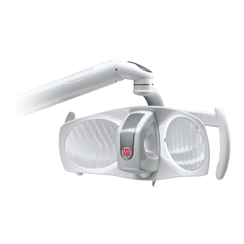
Faro MAIA User manual

USER’S MANUAL

MAIA USER’S MANUAL - EN
COD. 988300 Edition 2.22023-01 Pag. 2 di 8
Dear Customer,
FARO hopes you enjoy your work with the new high quality light. For safe work and to take full
advantage of the performance of the product, read carefully this manual before using the device.
In particular, follow all the warnings and the notes described into the Safety Recommendations included
in the Packaging.
Warranty Conditions:
FARO offers the final customer a 12 month warranty starting from the date of installation until a maximum of 18
months from the manufacturing date.
Repairs under warranty must be performed by FARO or its approved Service partner.
Warranty is considered valid only when:
•the user sent the Certificate of Warranty duly filled out at the following email: [email protected]t
•the user registered the warranty throughout the Faro website;
The warranty covers manufacturing and engineering defects; in case of valid claims, the warranty covers free parts
replacement only. Manhour work is not included in the warranty.
The warranty is not considered valid, at the sole discretion of FARO, if the fault is due to tampering, damage,
unauthorized changes to the product, incorrect use, improper maintenance and normal wear and tear.
This product have a Service Life of: 10 Years.
The Product is covered by the WEEE Directive 2012/19/EU. When scrapping and disposing of materials, follow the
regulations in force in your country, using recognised and authorised companies.
At the end of the life cycle, sort the materials according to their type (ferrous, rubber, plastic).
Any serious incident occurring in relation to the device should be reported to the Manufacturer and the competent
authority of the Member State in which the user and/or patient is established.
Table of contents
1SYMBOLS USED .................................................................................................................................................................................3
1.1 SYMBOLS USED IN THIS MANUAL ......................................................................................................................................3
1.2 SYMBOLS USED IN THE LABELLING AND ON THE PACKAGING...........................................................................3
2INTENDED USE .................................................................................................................................................................................3
2.1 USER’S MINIMUM REQUIREMENTS..................................................................................................................................3
3DESCRIPTION OF THE PRODUCT ...........................................................................................................................................4
4INSTRUCTION FOR USE ...............................................................................................................................................................4
4.1 DESCRIPTION OF COMMON USER’S INTERFACE .......................................................................................................4
4.2 SWITCHING ON/ OFF ...............................................................................................................................................................5
4.3 ADJUSTING THE LIGHT INSTENSITY ................................................................................................................................5
4.4 VIDEO RECORDING MODE.....................................................................................................................................................5
4.4.1 Video recording mode ON (or OFF) ..........................................................................................................................5
4.4.2 Adjusting Light intensity in Video Mode .................................................................................................................5
4.5 REMOTE CABLE...........................................................................................................................................................................5
4.6 AUTO-ON MODE .........................................................................................................................................................................5
4.7 USING THE POLIBLOCK FILTER ..........................................................................................................................................5
5CLEANING, DISINFECTION AND STERILIZATION............................................................................................................6
5.1 CLEANING OF THE MIRRORS...............................................................................................................................................6
5.2 CLEANING AND DISINFECTION OF THE HEAD ............................................................................................................6
5.3 CLEANING AND DISINFECTION OF ARMS......................................................................................................................6
5.4 DECONTAMINATION AND STERILIZATION OF PARTS ............................................................................................6
5.4.1 Decontamination And Disinfection Of The Handles ...........................................................................................6
5.4.2 Sterilization Of The Handles.......................................................................................................................................6
5.4.3 Decontamination And Disinfection Of Poliblock ..................................................................................................6
5.4.4 Sterilization Of Poliblock .............................................................................................................................................6
6PREVENTIVE MAINTENANCE AND ROUTINE CHECKS.................................................................................................7
7TROUBLESHHOTING .....................................................................................................................................................................7
8TECHCNICAL SPECIFICATION..................................................................................................................................................8

MAIA USER’S MANUAL - EN
COD. 988300 Edition 2.22023-01 Pag. 3 di 8
1SYMBOLS USED
1.1 SYMBOLS USED IN THIS MANUAL
WARNING
FORBIDDEN
The paragraphs marked with this symbol contain instructions that must be carefully followed
to avoid damaging the device, harming the operator or the patient.
This icon highlights what you should not do to avoid
damaging the device.
CAUTION
NOTES
These instructions warns you that you must pay attention to avoid situations that could
damage the device.
This icon supplies information that allows you to use
the device more efficiently.
1.2 SYMBOLS USED IN THE LABELLING AND ON THE PACKAGING
The data plate is fixed:
•for the complete light or arms: on the rear arm
•for the head: under the switch cover
Serial Number description
•For dental light YYLDNNNNNN
•For head of dental light YYTENNNNNN
Where
•YY: last two digit of the year of manufacturing
•NNNNNN: progressive counter of the year
e.g.: 21LD000001 I the first product manufactured in 2021.
Following symbols are present also:
Symbol
Description
Symbol
Description
Symbol
Description
Mark for Conformitè Europe
Can be sterilized with heat at 134°C
Fragile
Medical Device according to
Regulation (EU) 2017/745 on
medical devices,
Use the device at a temperature
between 10°C and 40°C
Protect the packaging from
rain and high humidity
Read the instructions use.
Supplied by Electronic means.
Use the device at pressure between
800 mbar and 1060 mbar
Do not Roll
Manufacturer symbol according
to Regulation (EU) 2017/745
Use the device at relative humidity
between 30 RH and 75RH
Do not use hooks
The instructions for use include
safety warnings
Serial Number
Maximum stackable weight
WEEE equipment according to
the Directive 2012/19/EC.
Symbol to adjust light intensity
Storage and Trasportation
temperatures
Double insulation. Class 2 device
against electrical risk
Symbol to switch on/off the
light
Storage and Trasportation
Relative Humidity
Recyclable cardboard
High
Swiss Authorized
Rapresentative for Medical
Device Regulation
(MedDo)
Storage and Trasportation
Atmospheric Pressure
2INTENDED USE
The device is used in dental cabinets and is intended for illuminating the oral cavity and oral structures of patients in dentistry.
In the normal use, the device is positioned distance of 700mm from the operative area, the distance for which the lighting features were designed.
Patients can be of all ages with typical dental pathologies.
2.1 USER’S MINIMUM REQUIREMENTS
The user with the following characteristics does not require any special training
Intended User
Professional qualification:
Minimum skills
Experience
Possible user handicaps
The intended users are
Dentists (all specializations)
or Dental Nurse, Hygienists
and Assistants
Degree in Medicine with
Dentistry Specialization
Degree in Dentistry
Degree in dental nursery
Those planned for the
professional qualification
Understanding of language:
Those acquired for the
professional qualification
Those outlined to
conduct the profession
For the use it is necessary at
least one upper limb;
Visual faculty compatible
with the profession;

MAIA USER’S MANUAL - EN
COD. 988300 Edition 2.22023-01 Pag. 4 di 8
3DESCRIPTION OF THE PRODUCT
1 –Post for connection to unit or ceiling
2a –Fixed arm unit mount
2b –Fixed Arm Ceiling Mount
3 –Joint of the fixed arm
4 –Rear Joint of swivel arm
5 –Swivel arm
6 –Joint of the Head
7 –Joke of the Head
7a –Joke of the head with 3rd axis
8 –Head light
Fig 1 –Maia Dental Light 3 axis unit mount
These main variants can be supplied with:
-Full dental light or Dental Light Head
-Command Interface: Mechanical Switch or Proximity Sensor
-Different Mounting (ceiling or dental unit)
-Different arm length combination
-Remote cable for bring the command to the Dental Unit’s
-Auto-on setting;
-Power supply (with or without integrated transformer)
Fig 2 –Maia Dental Light ceiling mount
All variants can be ordered by dedicated product codes as reported in the table below:
32X YWZ 3NN - 42X YWZ 3NN - 32X YWZ 0NN - 42X YWZ 0NN:
Axis of
rotation
X
Mounting -
Control
Y
Voltage input -
Control
W
Arm lenght
(mm)
Z
arm
shape
Type of
device
NN
Custom
32
standard
0
Unit std
0
24 Vac –MS (*)
1
750x550
0
Curved
3
Dental Light
00
Std FARO
42
3 axis
2
Unit Auto on
1
24 Vac –PS (*)
2
900x550
9
Straight
0
Head (*)
XX (**)
Custom
4
Unit Remote Cable
4
230Vac –MS
9
750x855
5
Ceiling std
5
230 Vac - PS
(*) MAIA can be supplied also with Direct Current 22 –35 Vdc
(**) Custom codes
MS: Mechanical Switch PS: Proximity Sensor
6
Ceiling Auto On
6
120 Vac - MS
1
Only Head std
7
120 Vac - PS
8
240Vac - MS
9
240Vac - PS
For the North American market (United States and Canada) the following variants are available: 32X YWZ 4NN - 42X YWZ 4NN:
Axis of
rotation
X
Mounting -
Control
Y
Voltage input -
Control
W
Arm lenght
(mm)
Z
arm
shape
Type of device
NN
Custom
32
standard
0
Unit std (**)
0
24 Vac –MS (*)
1
750x550
0
Curved
4
Dental Light
00
Std FARO
42
3 axis
2
Unit Auto on(**)
1
24 Vac –PS (*)
2
900x550
9
Straight
XX (**)
Custom
5
Ceiling std(**)
9
750x855
6
Ceiling Auto On
(**)
(*) MS: Mechanical Switch PS: Proximity Sensor
(**) Fixed equipments class I with earth protection connection
4INSTRUCTION FOR USE
4.1 DESCRIPTION OF COMMON USER’S INTERFACE
1 Mechanical Switch
2 Sterilisable Handle
3 Knob of the handle
4 Proximity Sensor
5 Mirrors
6 LED group
The device must be cleaned before use (see Device Cleaning paragraph).
WARNING AGAINST HAZARD OF EXPLOSION AND ELECTROMAGNETIC MALFUNCTIONING
Do not use the device in flammable or explosive environments
Simultaneous use of the light with electro-surgical devices can cause malfunctioning (flickering, no command, etc)
NOTE FOR POLYMERISATION OF RESTORATIVE COMPOSITES
MAIA is not equipped with anti-polymerisation function. To minimise the risk of polymerisation:
−Use the lamp at a light intensity close to the minimum; or
−Use the FARO Poliblock filter
FORBIDDEN
The joystick must be handled with care to avoid breakages.
Never move the light using the switch or parts other than the handles
WARNING OF PHOTOBIOLOGICAL HAZARD AND GLARE
Do not stare or aim the light beam directly into the patient's eyes, especially for patients at higher risk of eye injury (e.g. children or patient
with eye diseases). In this case, always use appropriate protection and precautions.
The lamp is classified as photobiological risk 1, without labelling according to IEC/EN 62471, at a distance of 200 mm.
However, it cannot be excluded that particularly photosensitive individuals, or those who have taken photosensitising substances, may
experience rashes or allergic reactions to light. In this case, discontinue treatment and use very low illuminance levels.
WARNING AGAINST THE DANGER OF SUSPENDED MASSES
Do not use the device if any parts or enclosure are damaged or if there is play or breaks between:
- Head joint / Head joke
- Fixed arm joint / Rear Joint of swivel arm
The device is equipped with limit switches on each rotating element. Do not move the lamp by hitting the limit switches.

MAIA USER’S MANUAL - EN
COD. 988300 Edition 2.22023-01 Pag. 5 di 8
4.2 SWITCHING ON/ OFF
Mechanical Switch
Proximity
Push right or left and release
Acoustic signal: 1 beep
Bring the hand towards the sensor up to 2 cm and move the
hand down
Acoustic signal: 1 beep
Each time the lamp is
switched on, the light
intensity will set
automatically on the
memorized at the
switch-off.
4.3 ADJUSTING THE LIGHT INSTENSITY
Switch –Increase Light Intensity
Switch - Decrease light intensity
Proximity
Push left and keep pushed until desired
intensity is reached. Then release
Acoustic signal: 1 beep at command
Maximum intensity reached: 2 beeps
Push right and keep pushed until desired
intensity is reached, then release.
Acoustic signal: 1 beep at command
Minimum intensity reached: 1 beep
Bring the hand towards the sensor up to 2 cm and keep this
distance until the desired light intensity is reached
Acoustic signal: 1 beep at command
Maximum intensity reached: 2 beeps
Minimum intensity reached: 1 beep
4.4 VIDEO RECORDING MODE
Maia is equipped with a function that allows it to be used during camera video recordings and/or the use of diagnostic instruments (e.g. Diagnodent and
laser) without the risk of interference that could affect the result.
The function is only present in Mechanical Switch (MS) version and can be activated or deactivated by the user.
4.4.1 Video recording mode ON (or OFF)
1. Switch on the dental lamp
2 Act on the control to reach the minimum light intensity (1 beep at minimum ).
3 Without release the MS, keep pushed for at least 4 seconds.
4. A confirmation beep is heard, the light intensity rises to the maximum level and the Video-
Diagnostics function is ON (or OFF).
If the procedure does not work, repeat it from point 1.
4.4.2 Adjusting Light intensity in Video Mode
In Video-Diagnostics Mode, the light intensity adjustment changes from continuous to stepwise.
Two intermediate levels of light intensity can be selected between maximum and minimum.
Procedure:
1. Switch on the Maia dental lamp using the MS (beep at the control socket).
2. Release the MS.
3. Push the MS again to reduce the light intensity and release the control at the desired intensity
level.
When the minimum intensity is
reached, a beep sounds.
When it is switched on again, the
dental lamp will return to full
brightness (beep at the control
socket).
4.5 REMOTE CABLE
Make reference to the Dental Unit’s instruction for use the Dental Light from the Dental
Unit’s control panel.
In case remote cable is managed in installation, ask the Installator.
Commands from remote cable are managed by a Push Button,
Function
Button
Command
On –Off
A
Press and Release
Adjustment
A
Press and keep pushed
4.6 AUTO-ON MODE
When the Auto On mode is on, the lamps switch on automatically (without a specific command from the user) when there is power from the dental unit.
To change the Auto On setting, contact a Service Engineer.
4.7 USING THE POLIBLOCK FILTER
The anti-polymerisation filter "POLIBLOCK" modifies the light spectrum,
avoiding the activation of the composite up to 520 nm wavelength. The device
can be applied to MAIA directly by the end user during dentistry procedures.
Insert the POLIBLOCK filter, checking that it well secured to the LED group.
The light emitted by the lamp with the "POLIBLOCK" turns to a red colour,
cutting the blue frequencies.
Use the POLIBLOCK only for the time necessary to the composite to be
modelled to the final shape.
Table of contents
Other Faro Dental Equipment manuals