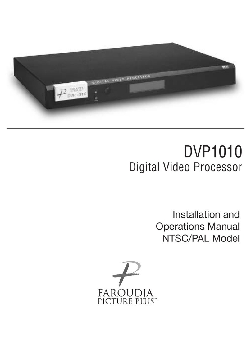
Faroudja DVP 1080 User manual

DVP1080
HD Digital Video Processor
Frequently Asked Questions

DVP-1080 FAQ’s REV 06.20.05 Pearcision
2
PREFACE
The following FAQ’s are provided to resolve common system installation questions, which may occur
during setup and operation of the DVP1080 processor. Please review the DVP-1080 Installation and
Operation Manual completely, as it contains solutions to most issues.
The DVP-1080 Digital Video Processor is merely one piece of equipment within a complex Video/Audio
system. It is important to review all system component manuals, to insure all settings selected are
correct. It is also recommended to first contact your Faroudja Dealer, or person that installed the system,
as they will have in-depth knowledge, regarding system connectivity. The Faroudja website also contains
these FAQ’s, and the Installation and Operation Manual, as well as additional resources to assist you.
www.faroudja.com
EXPRESS LINKS TO FAQ’s
Note: Select FAQ QUESTION to proceed to link. Select button to return to the main FAQ list.
A. Connecting the Processor to the Display
X1. Which output scanrate should I choose for my display?
X2. There are “sparkles” appearing throughout the image when using the DVI OUTPUT
X3. Can the DVP1080 simultaneously output an Analog and a Digital signal?
X4. Is the DVP-1080 capable of passing/processing an HDCP encrypted DVI/HDMI signal?
X5. Which type of DVI cable should I use from the processor to the display?
X6. How long can I run a DVI cable?
X7. Which output connection should I choose: DVI, BNC (RGBh/v) or MONITOR (VGA)?
X8. There is Dark Banding/Streaking throughout the video image; how do I fix this?
X9. My picture is Magenta or Pink in color.
X10. My picture is Green.
B. Connecting the Sources to the Processor
X1. Can the DVP-1080 process computer signals sent to the DVI INPUT or PASS-THRU input?
X2. There is no video from the DVI OUTPUT when the source is connected to the PASS-THRU input.
X3. There is no video from the ANALOG OUTPUTS when the source is connected to the DVI INPUT.
C. Processor Setup Questions
X1. I changed the output scanrate, but the processor did not register the scanrate selection.
X2. I selected SET: NTSC SCANRATE / 1920x1080, now there is no video output.
X3. Is SET: NTSC SCANRATE / 1920x1080 an Interlaced or Progressive video signal?
X4. My connection to the display device is Analog, which SET: ACTIVE OUTPUT format should I
choose, RGB or YPrPb?
Main Menu

DVP-1080 FAQ’s REV 06.20.05 Pearcision
3
D. Processor Operation Questions
X1. How do I discretely select the DVI INPUT, or RGB INPUT, using the IR Remote?
X2. The LCD display is displaying an OVERHEAT WARNING.
X3. How do I Store a Profile?
X4. When I select 4:3 on the IR remote, the image is not centered.
X5. The DVP-1080 has locked up. How do I reset the processor?
E. RS-232 Control Questions
X1. Where can I locate the RS-232 command protocol?
X2. How do I enter the RS-232 command string?
X3. I cannot Control the unit using RS232?
X4. How do I change the default RS-232 communication Baud Rate?
Main Menu
Download the DVP-1080 INSTALLATION AND OPERATION MANUAL now!
Note: An Internet Pop-Up Blocker may re-direct you to the FAROUDJA Home Page. Product
Manuals are located under the SUPPORT tab. For Direct Download from this FAQ page, Press
and Hold the [Ctrl] button on your computer keyboard, while selecting the web Web-Link above.

DVP-1080 FAQ’s REV 06.20.05 Pearcision
4
A. Connecting the Processor to the Display
A.1. Which output scanrate should I choose for my display?
The appropriate output scanrate selection is usually determined by the actual native pixel density of a digital
display device, or the physical CRT size of an analog display device (7”, 8” or 9” CRT).
Each display device will specify their individual video/computer input capabilities. All display devices will list
their specific video/computer input specifications within the User’s Manual, and are typically located within a
“Table of Supported Resolutions”, or under similar nomenclature.
The following represent basic examples for possible output scanrate selections:
Display Type Plasma TV Digital Projector CRT Projection CRT Rear Screen
Display Resolution 1366 x 768 1280 x 720 7” CRT 8” CRT 9” CRT 480i/p, 1080i, or 720p
DVP-1080
OUTPUT SCANRATE 1366 x 768 1280 x 720
1920 x 540
or
1280 x 720
1280 x 720
or
1440 x 960
1440 x 960
or
1920 x 1080
1920 x 540p
or
1280 x 720p
Note: Occasionally, a digital display device may not actually accept the signal received from the processor
at its native pixel resolution. Choose a standard DTV signal in this instance, such as 1280x720
(default setting), or 1920x540 (1080i equivalent).
A.2. There are “sparkles” appearing throughout the image when using the DVI OUTPUT
Cable length is too long to support the output resolution selected on the processor
•“Sparkles” may occur if the resolution selected on the DVP-1080 processor has exceeded the ability of
the DVI cable to transmit all of the video data (missing bits = sparkles). This is directly dependent upon
cable quality (contact cable manufacturer regarding length to resolution specifications).
•Unassisted DVI cable lengths to 50ft (15.24m) have been achieved with resolutions of 1024p and lower.
•Cable lengths of 50ft (15.24m), or greater, may require a DVI to Fiber Optic cable connection between the
processor and display for resolutions higher than 1024p; consult Cable Manufacturer
A.3. Can the DVP1080 output both an Analog and a Digital signal simultaneously?
Yes. Four (4) potential SET: ACTIVE OUTPUT modes are available through the DVP-1080 SETUP MENU.
•ANALOG RGB + DVI Both DVI OUTPUT and ANALOG OUTPUTS are active (Default Setting)
•ANALOG RGB Only ANALOG OUTPUTS are active (RGBh/v and MONITOR)
•DVI Only DVI OUTPUT is active (RGBh/v and MONITOR out disabled)
•ANALOG YPrPb Only ANALOG OUTPUTS are active (DVI output disabled)
Note: When SET: OUTPUT FORMAT / ANALOG YPrPb has been selected through the SETUP MENU,
the DVI OUTPUT will be disabled, as the required output signal for DVI is RGB only.
A.4. Is the DVP-1080 capable of passing/processing an HDCP encrypted DVI/HDMI signal?
Yes. However, the DVI INPUT on the display device must also be HDCP compliant to view the image, or the
HDCP encryption “handshake” will be broken. If digital “snow”, or a message dialog box appears on HDCP
Main Menu
Main Menu
Main Menu

DVP-1080 FAQ’s REV 06.20.05 Pearcision
5
encrypted signals to make an alternate connection, you should then check the display’s Operations Manual to
verify HDCP compliance.
Note: A DVI signal that is HDCP encrypted will deactivate the ANALOG OUTPUTS.
A.5. Which type of DVI cable should I use from the processor to the display?
It is recommended to install a DVI-D, Single-Link cable connection.
The physical DVI connection IN and OUT of the DVP-1080 is a DVI-I, Dual-Link connector. However, the
DVP-1080 internal pin out configuration is for a DVI-D, Single-Link cable connection. This allows for system
connection flexibility. The display device will typically have a DVI-D type connector.
A.6. How long can I run a DVI cable?
High resolution displays require a high quality DVI cable connection from the processor to the display. DVI
cables must be rated to support the scanrate and length to be implemented; up to 50 foot non-fiber cables are
okay for scanrates 1280x1024 and below. Higher scanrates, such as 1920x1080p, require the DVI cable be
rated to at least 1600x1200 for the cable length required. A DVI to fiber optic cable is highly recommended
for cable lengths longer than 16 feet (5m).
If the DVI cable has exceeded its ability to support the resolution selected, you may experience “sparkles”
and/or digital noise throughout the video, or no video at all. To insure installation success, you should always
test your connections, prior to installation.
A.7. Which output connection should I choose: DVI, BNC (RGBh/v) or MONITOR (VGA)?
When available, the DVI OUTPUT should always be utilized first. However, it is also recommended to route
an analog RGBh/v cable to enable system expandability.
DVI OUTPUT:
Choose this connection first, unless the display device does not support this type input connection.
BNC (RGBh/v) Output:
Choose the BNC output connections for analog display devices that do not have a DVI input connection.
When SET: ACTIVE OUTPUT / DVI is selected within the SETUP MENU, the ANALOG OUTPUTS are
disabled; however, will pass analog to analog signals (select appropriate input on the display device).
MONITOR (VGA) Output:
The MONITOR output connection, though convenient, is designed for short cable runs of nine (9) feet, or less.
The BNC (RGBh/v) output is recommended first.
When SET: ACTIVE OUTPUT / DVI is selected within the SETUP MENU, the ANALOG OUTPUTS are
disabled; however, will pass analog to analog signals (select appropriate input on the display device).
Note: There is inherent signal degradation utilizing the MONITOR output for cables runs over nine (9) feet.
YPrPb Output (Component):
Select this output format only when the display device does not support either a DVI, RGBh/v, or 15-pin
(VGA) input connection. Select SET: NTSC SCANRATE / 1280x720 or 1920x540 (1080i equivalent), as
these scanrates are the only valid Component video output formats which the display will understand; both
output scanrates are recognized by the display device as a DTV video signal.
When SET: ACTIVE OUTPUT / DVI is selected within the SETUP MENU, the ANALOG OUTPUTS are
disabled; however, will pass analog to analog signals (select appropriate input on the display).
Main Menu
Main Menu
Main Menu
Main Menu
DVP-1080 FAQ’s REV 06.20.05 Pearcision
6
A.8. There is “Dark Banding/Streaking” while the video image is changing; how do I fix this?
The video image is either positioned (Phased) too far to the left/right, or the image is too wide. Though the
image may be “filling” the viewable screen area, the display is having difficulty finding the actual Clamp Pulse
(sync signal). The display is now “Clamping” to the Peak Whites of the video signal; or rather, “clamping” to
video, not the sync pulse.
You should recalibrate the display device utilizing a master video test pattern. Utilize a Component (YCrCb)
DVD source and a Safe-Area test pattern (AVIA or DVD Essentials calibration DVD).
Digital Display Device (Plasma, D-ILA, DLP or LCD)
•Utilize a “Screen Area” test pattern from a calibration test DVD
•Reduce the video image size until you see the Active Picture area of both the left side and right side of
the video image
•Center the image on the screen using the positioning controls of the display device only
•Digital displays will have sizing controls labeled Pixel Clock, Dot Clock or just Clock, etc. This
adjustment will expand/contract the image to from the Right; the Left side of the image should remain
relatively fixed to its position
•Use Horizontal Size, Positioning controls and Clock adjustment to center/position the image on screen.
You will need to utilize all controls to achieve/massage image centering
•Once the image is centered correctly, fully expand the image to the edge of the screen
Analog CRT Display Device
•Use a “Screen Area” setup pattern from a calibration test DVD
•Reduce the image size by 10% to 15%
•Un-blank Left, Right, Top and Bottom Blanking
•Increase BRIGHTNESS to 75%
•Image should be clearly seen within the raster area
•Phase picture to center image within the raster area
•Center raster (with image) on the screen
•Blank Left, Right, Top and Bottom Blanking to edge of image
•Increase Left/Right and Top/Bottom Size to the edge of screen
A.9. My picture is Magenta or Pinkish in color.
RGBh/v out into YPrPb in = MAGENTA picture.
The default analog ACTIVE OUTPUT of the DVP-1080 is 5-wire RGB (RGBh/v). If your only video input
option to the display is via YPrPb, you must first change the ACTIVE OUTPUT on the DVP-1080 from RGB
to YPrPb within the SETUP MENU.
Note: The DVI OUTPUT is disabled once YPrPb has been selected; YPrPb is not a valid output format
within the DVI domain.
•Enter the SETUP MENU by pressing the [MENU] button on the IR remote for seven (7) seconds
•Press the [▲]arrow button until the upper LCD display reads either of the following:
oSET: OUTPUT FORMAT / ANALOG RGB + DVI
oSET: OUTPUT FORMAT / ANALOG RGB
•Press the [◄] or [►]arrow button to select SET: OUTPUT FORMAT / ANALOG YPrPb
Main Menu

DVP-1080 FAQ’s REV 06.20.05 Pearcision
7
•Press the [MENU] button to return to the USER MENU
Note: ONLY select either 1920x540p or 1280x720p scanrates if the display device does not have an
available 5-wire RGBh/v or D-15 VGA input connection.
•If you are connecting the DVP-1080 and display device via RGBh/v, and your picture is MAGENTA, you
will then need to change the displays input format from COMP (Component) to RGB or PC.
•Verify that the output/input cable(s) have not been swapped.
•Verify continuity of cable terminations
A.10. My picture is Green.
YPrPb OUT into RGBh/v IN = GREEN picture.
The BNC’s (RGBh/v), or MONITOR output of the DVP-1080 is connected to the RGBh/v, or VGA input of the
display device. However, SET: ACTIVE OUTPUT/ ANALOG YPrPb has been incorrectly selected.
•Enter the SETUP MENU by pressing the [MENU] button on the IR remote for seven (7) seconds
•Press the [▼]arrow button until the LCD display reads SET: ACTIVE OUTPUT / ANALOG YPrPb
•Press the [◄] or [►]arrow button to select one of the following
oSET: ACTIVE OUTPUT / ANALOG RGB + DVI
oSET: ACTIVE OUTPUT / ANALOG RGB
•Press the [MENU] button to return to the USER MENU
OR:
•You have selected [RGB] on the IR remote; press the [YCrCb] button on the IR remote
•A Component HDTV (YPrPb) output format has been connected to the PASS-THRU (VGA) input.
However, the connection from the DVP-1080 to the display is via RGBh/v out or MONITOR out.
oConnect the HDTV (YPrPb) output signal to the Component input on the DVP-1080 processor.
oConnect a Component (YPrPb) to RGBh/v Transcoder between the HDTV source and the analog
PASS-THRU input on the DVP-1080 processor.
Note: A transcoder converts an analog YPrPb signals into an RGBh/v signal
•Verify that the output/input cable(s) have not been swapped.
•Verify continuity of cable terminations
Main Menu
Main Menu

DVP-1080 FAQ’s REV 06.20.05 Pearcision
8
B. Connecting the to Sources to the Processor
B.1. Can the DVP-1080 process computer signals sent to the DVI INPUT or PASS-THRU input?
No. The DVP-1080 will only route a digital or analog computer signal directly to the pass-through circuitry.
Analog (VGA):
When an analog computer source is connected to the PASS-THRU input, you must connect an RGBh/v cable
to the display device. The processor will not convert an analog VGA signal to DVI; the display device must
also be capable of the resolution selected on the computer source.
Digital (DVI):
When a digital computer source is connected to the DVI INPUT, you must connect a DVI cable to the display
device. The processor will not convert a digital DVI computer source to RGBh/v; the display device must also
be capable of the resolution selected on the computer source.
B.2. There is no video from the DVI OUTPUT when the source is connected to the PASS-THRU
input.
The D-15 PASS-THRU input will only route RGBh/v or YPrPb (Component) signals to pass-through via the
ANALOG OUTPUTS of the DVP-1080 (Analog IN = Analog OUT). It is always recommended to install both
an RGBh/v cable and a DVI cable to the display device for system expandability.
If the display does not have an RGBh/v, or D-15 (VGA) input connection, install a 3-wire Component analog
cable to the display; however, only 480i, 480p, 720p and 1080i are valid Component video signals.
B.3. There is no video from the ANALOG OUTPUTS when the source is connected to the DVI
INPUT.
•A DVI input signal that is HDCP encrypted will deactivate the ANALOG OUTPUTS. HDCP encrypted
signals can only connected to the display device using the DVI OUTPUT.
•The DVI input originates from a computer source. All VESA computer resolutions are sent directly to
pass-through in the same format received (Digital IN = Digital OUT).
Main Menu
Main Menu
Main Menu

DVP-1080 FAQ’s REV 06.20.05 Pearcision
9
C. Processor Setup Questions
C.1. I changed the output scanrate, but the processor did not register the scanrate selection.
Changing the output scanrate requires confirmation of the new output scanrate selection. Do not select an
output scanrate which exceeds display device capabilities (refer to display device User’s Manual).
•Enter the SETUP MENU by pressing the [MENU] button on the IR remote for seven (7) seconds
•Front Panel LCD display will indicate SET: NTSC SCANRATE and the current RESOLUTION below
•Press the [◄] or [►]arrow button on the IR remote to select the appropriate output scanrate
•Press the [STORE] button on the IR remote
•Front Panel LCD display will indicate ARE YOU SURE?
•Press the [STORE] button to confirm resolution selection
Note: Use the same procedure above during SET: PAL SCANRATE, if applicable (International use)
C.2. I selected, SET: NTSC SCANRATE / 1920x1080, now there is no video output.
The 1920x1080 output scanrate is a Progressive Format (67.43kHz), not a 1080i HDTV Interlaced Format
(33.75kHz). The display device must be capable of receiving this scanrate (refer to display User’s Manual).
When utilizing the DVI OUTPUT, cable lengths to support 1920x1080p should be no greater than 16ft (5m).
Cable lengths longer than 16ft (5m) may require a DVI to Fiber Optic connection. DVI cable lengths longer
than 16ft (5m) may render an unstable image, “sparkles” throughout the image, or no image at all.
Note: Some digital displays may have a physical pixel density of 1920x1080, but will not display the actual
1920x1080p/60Hz signal received by the DVP-1080 processor. Example: 1920x1080, 24p/sF. Think
of 24p/sF as an Interlaced signal, whereby, a Progressive HD Segmented Frame is displayed as two
individual frames (similar to 1080i), then spliced back together; an Interlaced Format.
C.3. Is SET: NTSC SCANRATE / 1920x1080 an Interlaced or Progressive video signal?
The 1920x1080 output scanrate selection is a Progressive Format signal (67.4KHz, 60Hz refresh). Typically,
only high resolution displays will accept/resolve this input signal, such as 9”CRT projection, or a digital display
device with a native pixel density of 1920x1080.
Note: Some digital displays will have a physical pixel density of 1920x1080; however, may not accept this
input scanrate. If not, the image may either be split, or half the image is present, or no image at all.
Refer to display user’s manual for signal compatibility.
If the display does not accept 1920x1080 at 60Hz, then you must choose an alternate resolution the
display will understand, such as 1280x720 or 1920x540p (1080i equivalent). Both output resolutions
are perceived by the display as a DTV video signal.
W A R N I N G
DAMAGE may occur if the output scanrate selected within the DVP-1080 SETUP MENU exceeds the
ability of the display device to show the image.
Main Menu
Main Menu
Main Menu

DVP-1080 FAQ’s REV 06.20.05 Pearcision
10
C.4. My connection to the display device is Analog, which SET: ACTIVE OUTPUT format
should I choose, RGB or YPrPb?
SET: ACTIVE OUTPUT / ANALOG RGB + DVI and SET: ACTIVE OUTPUT / ANALOG RGB
When DVI is not available, the preferred analog output selection from the DVP-1080 is always RGB,
intimating RGBh/v. This produces the highest quality analog signal, as the processor will have pre-decoded
the incoming video signal to its fundamental constituents of Red, Green, Blue, horizontal sync/vertical sync.
SET: ACTIVE OUTPUT / ANALOG YPrPb
When DVI is not available, and display does not have either an RGBh/v or 15-pin (VGA) input connection,
select SET: ACTIVE OUTPUT / ANALOG YPrPb from within the SETUP MENU.
You must also select either SET: NTSC SCANRATE / 1280x720 or 1920x540 (1080i equivalent), as these
scanrates are the only valid Component video output formats which the display will understand; both the
1280x720 and 1920x540 scanrates are recognized by the display device as a DTV video signal.
Main Menu

DVP-1080 FAQ’s REV 06.20.05 Pearcision
11
D. Processor Operation Questions
D.1. How do I discretely select the DVI INPUT, or RGB INPUT, using the IR remote?
Discrete IR access to the DVI INPUT, or RGB INPUT, is available utilizing the IR remote and performing a
two (2) button sequence. Implementation of this two-step button sequence can be issued a macro, for use
with advanced programmable IR remotes.
•DVI Press the [DVI/RGB] button, then the [0] button on the IR remote
•RGB Press the [DVI/RGB] button, then the [1] button on the IR remote (RGB is typically for PAL use only)
Note: Learn each IR remote function individually and allow a 250ms (¼ second) delay between commands
D.2. The LCD is displaying an OVERHEAT WARNING.
The DVP-1080 processor possesses thermal protection circuitry which actively monitors internal temperature
during operation. Excessive heat may cause the processor to malfunction, and/or, shorten product lifespan.
•Do not mount processor above power amplifiers or other equipment which generate excessive heat
•Allow a minimum of one rack space, above and below the unit, for proper ventilation (1RU or 1.75”).
•Insure there is adequate system rack ventilation (preempts failure with additional installed equipment)
•LEVEL 1 WARNING / HIGH TEMPERATURE
Internal Temperature is exceeding safe operational limits. Steps should be taken to improve ventilation
•LEVEL 2 WARNING / HIGH TEMPERATURE
Internal Temperature is at critical thermal limits; processor failure may occur. Immediate steps should be
implemented, to improve ventilation, and return the unit to optimal operational temperature
•LEVEL 3 WARNING / EXTREME TEMPERATURE
Internal Temperature has exceeded maximum thermal limitations; processor will shut down.
oA LEVEL 3 WARNING will only display for Five (5) Seconds, then the DVP-1080 will shut down
oDVP-1080 cannot be powered ON by the front panel power button during this condition
oA LEVEL 3 WARNING indication requires the unit first be unplugged to reset
oNormal operation resumes once the DVP-1080 has returned to optimal thermal temperature
D.3. How do I Store a Profile?
A stored PROFILE is merely a “Snap-Shot-In-Time” for all settings which have been selected from both the
SETUP MENU options (LCD), or the USER MENU (OSD) options, within the DVP-1080 processor, and
programmed into the processor’s CPU.
System SETUP MENU Option (LCD)
•Enter the SETUP MENU by pressing the [MENU] button on the IR remote for seven (7) seconds
•Select all applicable changes required for the intended PROFILE within the SETUP MENU
•Press the [MENU] button to exit the SETUP MENU
•Then, proceed to…
On-screen USER MENU Options (OSD)
•Press the [MENU] button to view the On-Screen Display (OSD)
Main Menu
Main Menu

DVP-1080 FAQ’s REV 06.20.05 Pearcision
12
•Adjust all applicable changes required for the intended PROFILE
•Under the menu tab INPUT, use the [▼]arrow button to highlight PROFILE
•Press the value [►]button to select numeric PROFILE
•Press the [STORE] button
•Press the [MENU] button to exit the On-Screen Display
D.4. When I select 4:3 on the IR remote, the image is not centered.
This essentially means the innate 16:9 image from the DVP-1080, when selecting ANAMORPHIC, is not
properly centered on the display device.
•Utilize a DVD ‘Screen Area’ test pattern (DVD Essentials, AVIA, etc.)
•Center, and position the image for a 2.5% over-scan, using the displays sizing and positioning controls.
•Once the image has been properly centered, sized and positioned (utilizing the display controls), the 4:3
image will fall-in-to-place and be centered within the 16:9 display area.
Note: Do not view a 4:3 images for prolonged periods of time on a 16:9 display; image Burn-In may occur.
Image Burn-In is not covered under the Faroudja Warranty.
D.5. The DVP-1080 has locked up. How do I reset the processor?
There are three options available to re-boot the processor.
Level ONE:
Set the DVP-1080 unit in Stand-By mode; LED indication is RED. Disconnect the power plug from the
processor; reconnect the power plug to the processor and allow the unit to re-boot.
Level TWO:
•Enter the SETUP MENU by pressing the [MENU] button on the IR remote for seven (7) seconds
•Press the [▲]button on the IR remote once
•LCD display will indicate SET: RESTORE FACTORY / <PRESS STORE KEY>
•Press the [STORE] button on the IR remote
•Front Panel LCD display will indicate ARE YOU SURE?
•Press the [STORE] button again to confirm
Note: This action will clear all programmed PROFILES and reset the DVP-1080 to Factory Defaults.
Level THREE:
Connect to the DVP-1080 RS-232 CONTROL port using Windows HyperTerminal program and a standard
Modem Cable (please see FAQ instructions: “How do I enter the RS-232 command string?”).
TYPE dvp,setft[↵Enter] [↵Enter] denotes a carriage return, or pressing [↵Enter] button on the keyboard
Note: This action will clear all programmed PROFILES and reset the DVP-1080 to Factory Defaults.
Main Menu
Main Menu
Main Menu
DVP-1080 FAQ’s REV 06.20.05 Pearcision
13
E. RS-232 Control Questions
E.1. Where can I locate the RS-232 command protocols?
•Refer to the DVP-1080 Installation and Operation Manual.
•RS-232c Instructions and Commands are located within Pages 17 through 19 in the DVP-1080
Installation and Operation Manual. This manual also is available for download, via www.faroudja.com.
E.2. How do I enter the RS-232 command string?
The dvp header, followed by a comma, is utilized to delimit the header from the command (no spaces). The
following is a Windows HyperTerminal example, issuing Power ON, utilizing a standard Modem cable:
•dvp,on[↵Enter] [↵Enter] denotes a carriage return, or pressing [↵Enter] on the keyboard
Simultaneous commands may also be issued to the DVP-1080 processor by implementing a comma, to
delimit each command, prior to issuing the final carriage return, or rather, [↵Enter].
•dvp,x,a2,srn4[↵Enter] Control Syntax = Header dvp-1080, xYCrCb (Component Input), a2 Aspect
Anamorphic, srn4 Scanrate 1280x720[carriage return]. Do not insert spaces.
Note: An Eight (8) Second Delay will occur each time the DVP-1080 is powered ON while completing the
INITIALIZING process (FAROUDJA DVP SERIES / LOADING…….). Additional RS-232 commands
cannot be issued until the DVP-1080 has completed the LOADING/INITIALIZING sequence.
Personal Computer (PC Control)
•Use installed Windows HyperTerminal program to control the DVP-1080. Select the parameters listed
below and utilize a standard 9-pin Modem Cable (do not use a null-modem cable). Once connection has
been confirmed: TYPE dvp,help, then press the [↵Enter] key. The OPERATION COMMANDS will be
echoed back to your computer from the DVP-1080 processor.
oBits per second 19200
oData bits 8
oParity None
oS
top bits 1
oFlow control None
Note: An Eight (8) Second Delay will occur each time the DVP-1080 is powered ON while completing the
INITIALIZING process (FAROUDJA DVP SERIES / LOADING…….). Additional RS-232 commands
cannot be issued until the DVP-1080 has completed the LOADING/INITIALIZING sequence.
•Examples below are AMX and Crestron control commands; including their respective Carriage Returns.
oAMX "
'dvp,on',13"
"'dvp,off',13"
oCRESTRON dvp,on\r
dvp,off\r
E.3. I cannot control the unit using RS-232.
•Insure that connection is to the RS-232 CONTROL port, not the RS-232 OPTION port
•To review communication settings, please see FAQ “How do I enter the RS-232 command string?”
RS-232c Input
Pin 5 = Ground
Pin 3 = RX
Pin 2 = TX
1
6
9
5
Main Menu
Main Menu
Main Menu

DVP-1080 FAQ’s REV 06.20.05 Pearcision
14
E.4. How do I change the default RS-232 communication Baud Rate?
The DVP-1080 allows the ability to change the default 19200 baud rate from within the SETUP MENU.
•Enter the SETUP MENU by pressing the [MENU] button on the IR remote for seven (7) seconds
•Press the [▲]arrow button five (5) times, or until the LCD Display indicates SET: BAUD RATE / 19200
•Press either the [◄]or [►]arrow button to toggle to the appropriate baud rate for your control system:
oSET: BAUD RATE / 9600
oSET: BAUD RATE / 57600
oSET: BAUD RATE / 19200
Note: You are not required to press the [STORE] button to effect the baud rate change.
Main Menu

DVP-1080 FAQ’s REV 06.20.05 Pearcision
15
180 Baytech Drive, Suite 110 •San Jose, CA 95143
Phone: (408) 635-4200 •Fax: (408) 957-0364
www.faroudja.com
A division of Genesis Microchi
p
Inc.
Other manuals for DVP 1080
2
Table of contents
Other Faroudja DVD Player manuals

Faroudja
Faroudja DVP1080HD User manual

Faroudja
Faroudja Native Rate Series User manual

Faroudja
Faroudja NRS-DVI User manual

Faroudja
Faroudja Faroudja DVP1080MF User manual

Faroudja
Faroudja Native Rate Series User manual

Faroudja
Faroudja DVP 1080 User manual

Faroudja
Faroudja Native Rate Series User manual

Faroudja
Faroudja DVP1010 User manual

Faroudja
Faroudja DVP1510 User manual

Faroudja
Faroudja DVP1500 User manual