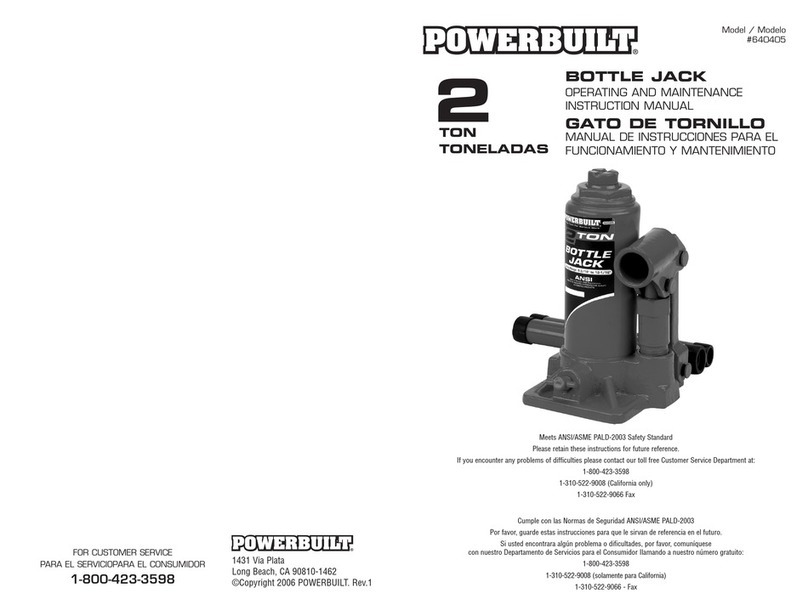
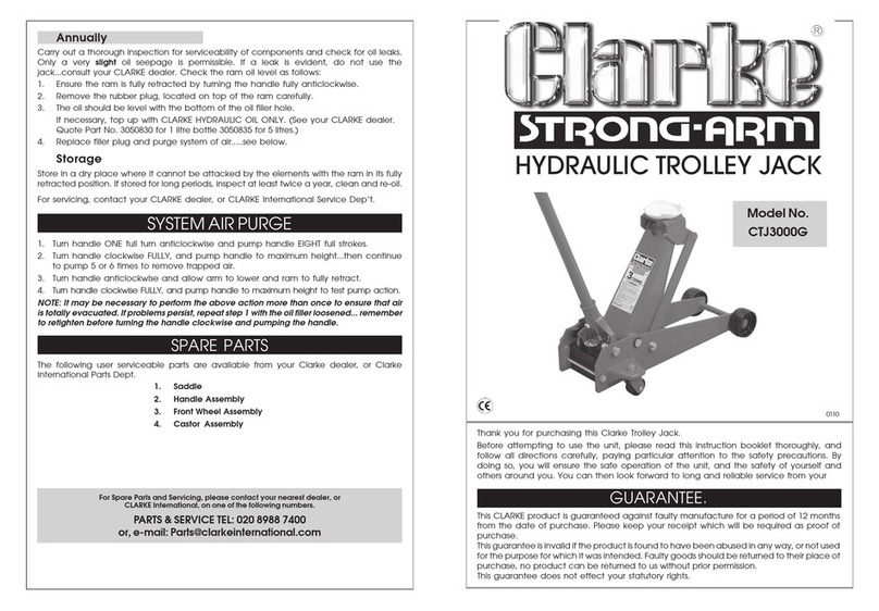
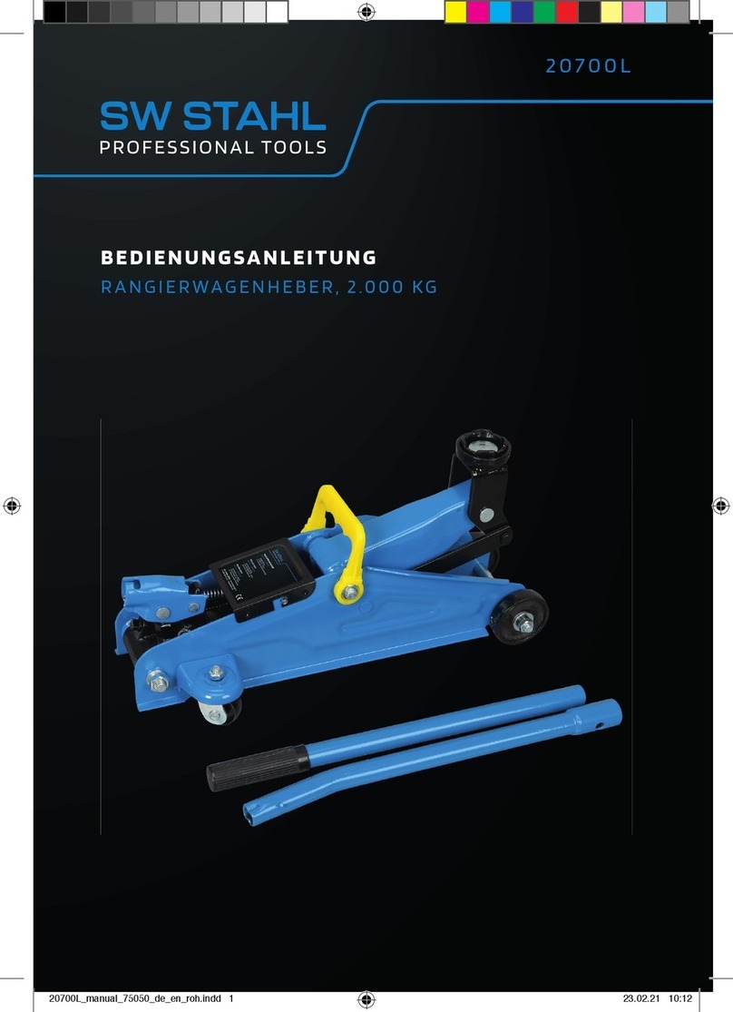
FASANO TOOLS FG 719/2T User manual

SOLLEVATORE IDRAULICO A CARRELLO
E’ vietata la riproduzione, anche in forma parziale, del presente documento senza l’autorizzazione scritta della FASANGAS S.r.l.
FG 719/2T
FG 718/2.5T
FG 718/3.5T

1
AVVERTENZE GENERALI
3
2
DESCRIZIONE DEL SOLLEVATORE E SPECIFICHE TECNICHE
3
3
IMPORTANTI ISTRUZIONI DI SICUREZZA
4
4
UTILIZZO
5
5
MANUTENZIONE
7
6
INFORMAZIONI PER LO SMALTIMENTO
7
7
DICHIARAZIONE CE DI CONFORMITA’
8
8
GARANZIA
8
SOLLEVATORE IDRAULICO A CARRELLO
2

I sollevatori idraulici a carrello sono macchine progettate esclusivamente per sollevare le
autovetture in fase di riparazione/manutenzione. Una volta sollevato il veicolo, utilizzare
dei cavalletti appropriati per sostenerlo.
Di seguito la tabella delle specifiche tecniche:
MODELLO:
FG 719/2T
PESO NETTO:
43.5 kg
PORTATA NOMINALE MASSIMA:
2 t
ALTEZZA MINIMA:
75 mm
ALTEZZA MASSIMA:
610 mm
MODELLO:
FG 718/2.5T
PESO NETTO:
30.0 kg
PORTATA NOMINALE MASSIMA:
2.5 t
ALTEZZA MINIMA:
75 mm
ALTEZZA MASSIMA:
510 mm
MODELLO:
FG 718/3.5T
PESO NETTO:
39.0 kg
PORTATA NOMINALE MASSIMA:
3.5 t
ALTEZZA MINIMA:
95 mm
ALTEZZA MASSIMA:
540 mm
Prima dell’utilizzo dell’utensile leggere attentamente le avvertenze e le istruzioni
contenute nel presente manuale.
L’uso improprio o non in sicurezza di questo utensile può risultare pericoloso o provocare
morte o gravi lesioni corporee.
Il presente manuale di avvertenze ed istruzioni costituisce parte integrante del prodotto e
deve essere conservato a cura dell’utilizzatore per eventuali future consultazioni. Esso
contiene importanti informazioni sulla sicurezza di utilizzo del prodotto.
Destinazione d’uso.
Il presente utensile ed i suoi accessori, devono essere utilizzati solamente per lo scopo cui
sono stati concepiti. Un utilizzo diverso da quello indicato potrebbe causare danni a
persone, animali o cose ed è considerato atto improprio ed irragionevole. Il costruttore non
può essere considerato responsabile per eventuali danni causati da usi impropri, erronei
ed irragionevoli, come ad esempio: inosservanza delle istruzioni ed avvertenze fornite,
utilizzo di accessori non originali, modifiche o interventi sul prodotto non autorizzati, ecc.
1. AVVERTENZE GENERALI
SOLLEVATORE IDRAULICO A CARRELLO
2. DESCRIZIONE DEL SOLLEVATORE E SPECIFICHE TECNICHE
3

Quando si adopera il sollevatore seguire sempre le seguenti istruzioni di sicurezza per ridurre i rischi di
lesioni personali:
Indossare sempre occhiali di sicurezza muniti di protezione laterale in accordo alle norme
vigenti.
Utilizzare guanti protettivi durante l’utilizzo dell’utensile in accordo alle norme vigenti.
Utilizzare indumenti protettivi adeguati durante l’utilizzo dell’utensile in accordo alle norme
vigenti.
Utilizzare calzature di sicurezza durante l’utilizzo dell’utensile in accordo alle norme vigenti.
Utilizzare il sollevatore esclusivamente su superfici d’appoggio piane non
sconnesse.
L’ambiente deve, inoltre, essere sufficientemente illuminato, tale da garantire
l’operatività in massima sicurezza.
I sollevatori idraulici a carrello sono macchine progettate esclusivamente per
sollevare le autovetture in fase di riparazione/manutenzione. Una volta
sollevato il veicolo, utilizzare dei cavalletti appropriati per sostenerlo.
Non lavorare mai sotto al veicolo sollevato. Per lavorarci posizionare
correttamente appropriati cavalletti per sorreggerlo.
•Non superare mai la porta nominale massima del sollevatore.
•Assicurarsi che non ci siano persone vicine al veicolo prima di sollevarlo.
•Prima di sollevare o abbassare il sollevatore, assicurarsi sempre che nessuna parte del
corpo sia sotto al veicolo
•Fare riferimento al manuale del costruttore del veicolo per sapere qual è il punto del veicolo
per il sollevamento.
3. IMPORTANTI ISTRUZIONI DI SICUREZZA
Il sollevatore idraulico a carrello è costituito dai seguenti componenti:
A–LEVA DI AZIONAMENTO
C–RUOTE POSTERIORI GIREVOLI
D –TELAIO
E–RUOTE ANTERIORI FISSE
F–BRACCIO SOLLEVATORE
G–PIATTELLO REGGI CARICO
H–PORTA MINUTERIA
SOLLEVATORE IDRAULICO A CARRELLO
4

DISIMBALLO E ASSEMBLAGGIO
1.
2.
3.
4.
5.
SOLLEVATORE IDRAULICO A CARRELLO
4. UTILIZZO
5

SPURGO DELL’ARIA
Le procedure di seguito riportate devono essere eseguite senza alcun carico sul sollevatore.
1.
2.
3.
4.
5.
6.
Eseguite le operazioni sopra riportate, il sollevatore sarà pronto per l’utilizzo (ripetere la procedura
se necessario)
SOLLEVAMENTO
1.Bloccare le ruote del veicolo per la stabilità di sollevamento. Assicurare il carico per evitare
spostamenti e spostamenti involontari.
2.Posizionare il sollevatore vicino al punto di sollevamento desiderato.
3.Inserire il freno di stazionamento nel veicolo.
4.Fare riferimento al manuale del produttore del veicolo per individuare i punti di sollevamento.
Posizionare il sollevatore in modo che il piattello sia centrato e a contatto con il punto di
Prima di utilizzare il sollevatore eseguire lo spurgo del sistema idraulico: durante il
trasporto si potrebbe accumulare dell’aria nel sistema idraulico che potrebbe
compromettere il corretto funzionamento del sollevatore.
SOLLEVATORE IDRAULICO A CARRELLO
6

sollevamento del carico. Sollevare tramite il manico fino a raggiungere l'altezza desiderata. Dopo
il sollevamento, fissare e trasferire il carico su cavalletti o altri mezzi appropriati. Non utilizzare
MAI il sollevatore come unico mezzo di supporto.
5.Chiudere la valvola di sfiato ruotando la leva in senso orario fino a quando la valvola non è ben
chiusa.
6.Prima di sollevare il veicolo ricontrollare e verificare che il piattello sia centrato e che sia anche a
pieno contatto con il punto di sollevamento.
7.Muovere la leva in su e in giù per sollevare finché il piattello non tocca il carico. Continuare
sollevare il veicolo all'altezza desiderata. Dopo il sollevamento, supportare il carico su opportuni
cavalletti di sostegno.
ABBASSAMENTO
1.Sollevare il carico abbastanza in alto da consentire la rimozione dei cavalletti di sostegno.
2.Rimuovere i cavalletti di sostegno.
3.Afferrare saldamente la maniglia del sollevatore.
4.Aprire con cautela la valvola di rilascio ruotando lentamente la maniglia in senso antiorario.
(assicurarci che non ci sia nessuno vicino al carico).
5.Una volta rimosso il carico dal sollevatore, posizionare il sollevatore completamente abbassato
in modo tale da evitare l’esposizione alla polvere/detriti e alla ruggine.
NOTA: riporre sempre il sollevatore in posizione completamente abbassata e la maniglia in
posizione verticale.
Quando il sollevatore non è in uso riporlo con il braccio di sollevamento completamente abbassato.
Tenerlo sempre in buono stato, pulito e lontano dalla portata dei bambini.
Per verificare il livello dell’olio, aprire la valvola di rilascio ruotando in senso antiorario la leva di
azionamento (A) e, abbassare al minimo il piattello reggi carico. Rimuovere il tappo dell’olio.
Assicurarsi di non introdurre polvere e corpi estranei insieme al nuovo olio. Se il livello dell’olio è
basso, il sollevatore non riuscirà a raggiungere la massima altezza. NON utilizzare MAI olio per
freni, per turbine, per cambi o motore. L’utilizzo di olio inappropriato può danneggiare il sollevatore
portando alla perdita della portata massima di carico. Utilizzare esclusivamente olio per sollevatori
idraulici (ISO 32). Rimettere il tappo dell’olio.
Lubrificare i componenti del sollevatore quando necessario per evitare la formazione di ruggine e
usura.
Quando l’utensile non è più utilizzabile né tanto meno riparabile, smaltirlo secondo le norme
vigenti del luogo al fine di salvaguardare l’ambiente.
5. MANUTENZIONE
6. INFORMAZIONI PER LO SMALTIMENTO
SOLLEVATORE IDRAULICO A CARRELLO
7

Questo utensile è garantito privo di difetti di produzione e nei materiali, per un uso normale di servizio,
per un periodo di un anno dalla data di acquisto dell’utensile. Qualora in tale periodo si dovessero
riscontrare sull’utensile difetti imputabili al produttore, la ditta Fasangas S.r.l. agirà, a propria
discrezione riparando l’utensile o sostituendo con altro di pari valore e caratteristiche senza alcuna
spesa per l’acquirente. La garanzia non copre materiali di consumo e/o componenti soggetti a
particolare usura e guasti causati da un uso inappropriato o errato dell’utensile o comunque non
conforme a quanto dettagliato in questo manuale. Il diritto di garanzia decade qualora lo strumento
sia stato manomesso da personale non autorizzato dalla Fasangas S.r.l. I prodotti privi del diritto di
garanzia saranno riparati a totale carico del cliente.
8. GARANZIA
SOLLEVATORE IDRAULICO A CARRELLO
7. DICHIARAZIONE CE DI CONFORMITA’
8

HYDRAULIC TROLLEY JACK
The reproduction of this document (even in partial form) is prohibited without the Fasangas S.r.l. authorization
FG 719/2T
FG 718/2.5T
FG 718/3.5T

1
GENERAL WARNINGS
11
2
DESCRIPTION AND TECHNICAL FEATURES
11
3
IMPORTANT SAFETY INSTRUCTIONS
12
4
INSTRUCTIONS FOR THE USE
13
5
MAINTENANCE
15
6
DISPOSAL INFORMATIONS
15
7
EC DECLARATION OF CONFORMITY
16
8
WARRANTY
16
HYDRAULIC TROLLEY JACK
10

Hydraulic trolley jacks are machines designed exclusively to lift cars during repair /
maintenance. Once the vehicle is raised, use appropriate jack stands to support it.
In the following technical features:
MODEL:
FG 719/2T
NET WEIGHT:
43.5 kg
RATED LOAD:
2 t
MINIMUM LIFTING HEIGHT:
75 mm
MAXIMUM LIFTING HEIGHT:
610 mm
MODEL:
FG 718/2.5T
NET WEIGHT:
30.0 kg
RATED LOAD:
2.5 t
MINIMUM LIFTING HEIGHT:
75 mm
MAXIMUM LIFTING HEIGHT:
510 mm
MODEL:
FG 718/3.5T
NET WEIGHT:
39.0 kg
RATED LOAD:
3.5 t
MINIMUM LIFTING HEIGHT:
95 mm
MAXIMUM LIFTING HEIGHT:
540 mm
Before to use the tool, please read carefully the instruction contained in this
manual.Improper or unsafe use of this tool can result in death or serious bodily
injury.
This manual of instructions constitutes an integral part of product and it has to be edited
by the end user for every possible future consultation. It contains important informations
about the safety use of the product.
Use destination.
This tool and its accessories, must only be used for the purpose for which they have been
conceived. A different use from that one suitable could cause damages to people, animals
or things and it’s considered improper and unreasonable action. The producer can’t be
considered responsible for possible damages caused by improper, wrong and
unreasonable uses, as,for example, the un-observance of the safety instruction, the use
of no original accessories and operation not authorized on the product.
1. GENERAL WARNINGS
2. DESCRIPTION AND TECHNICAL FEATURES
HYDRAULIC TROLLEY JACK
11

When operating the trolley jack, always follow the following safety instructions to reduce the risk of
personal injury:
Always wear safety goggles with side protection in accordance with current regulations.
Use protective gloves when using the tool in accordance with current regulations.
Use suitable protective clothing when using the tool in accordance with current regulations.
Use safety shoes when using the tool in accordance with current regulations.
Use the trolley jack only on flat, non-disconnected support surfaces.
The environment must also be sufficiently illuminated, to ensure operation in
maximum safety.
Hydraulic trolley jacks are machines designed exclusively to lift cars during
repair / maintenance. Once the vehicle is raised, use appropriate jack stands
to support it.
Never work under the raised vehicle. To work with it, correctly position
appropriate stands to support it.
•Never exceed the lift's maximum rated door.
•Make sure that there are no people near the vehicle before lifting it.
•Before raising or lowering the lift, always make sure that no part of the body is under the
vehicle
•Refer to the vehicle manufacturer's manual to find out where the vehicle is to be lifted.
3. IMPORTANT SAFETY INSTRUCTIONS
The hydraulic trolley jack has the following components:
A–ACTION HANDLE
C–SWIVEL REAR WHEELS
D–FRAME
E–FIXED FRONT WHEELS
F–LIFT ARM
G–LOAD PLATE
HYDRAULIC TROLLEY JACK
12

UNPACKING AND ASSEMBLY
1.
2.
3.
4.
5.
4. INSTRUCTIONS FOR THE USE
HYDRAULIC TROLLEY JACK
13

SYSTEM AIR PURGE PROCEDURE
The following procedures must be performed with no load on the trolley jack.
1.
2.
3.
4.
5.
6.
Once the above operations have been carried out, the lift will be ready for use (repeat the procedure
if necessary).
Before using the lift, bleed the hydraulic system: during transport, air could accumulate
in the hydraulic system which could compromise the correct operation of the lift.
HYDRAULIC TROLLEY JACK
14

RAISING THE JACK
1. Lock the vehicle wheels for lifting stability. Secure the load to avoid involuntary displacements
and displacements.
2. Position the jack close to the desired lifting point.
3. Apply the parking brake in the vehicle.
4. Refer to the vehicle manufacturer's manual to locate the lifting points. Position the jack so that
the plate is centered and in contact with the lifting point of the load. Lift by the handle until the
desired height is reached. After lifting, secure and transfer the load to jack stands or other
appropriate means. NEVER use the jack as the only means of support.
5. Close the release valve by turning the lever clockwise until the valve is firmly closed.
6. Before lifting the vehicle double check and verify that the plate is centered and that it is also in
full contact with the lifting point.
7. Move the lever up and down to lift until the plate touches the load. Continue raising the vehicle
to the desired height. After lifting, support the load on suitable support stands.
LOWERING THE JACK
1. Raise the load high enough to allow removal of the jack stands.
2. Remove the jack stands.
3. Firmly grasp the lift handle.
4. Carefully open the release valve by slowly turning the handle counterclockwise. (Make sure no
one is near the load).
5. Once the load has been removed from the trolley jack, position the trolley jack completely
lowered in order to avoid exposure to dust / debris and rust.
NOTE: always store the trolley jack in the fully lowered position and the handle in the upright
position.
When the trolley jack is not in use, store it with the lift arm fully lowered. Always keep it in good
condition, clean and out of the reach of children.
To check the oil level, open the release valve (A) by turning it counterclockwise and lower the load
plate to a minimum. Remove the oil cap. Make sure not to introduce dust and foreign bodies with
the new oil. If the oil level is low, the lifter will not be able to reach the maximum height. NEVER
use brake, turbine, gearbox or engine oil. The use of inappropriate oil can damage the lift leading
to the loss of the maximum load capacity. Use only hydraulic lift oil (ISO 32). Put the oil cap back
on.
Lubricate the trolley jack components as needed to prevent rust and wear.
When the trolley jack is no longer usable nor repairable, dispose of it according to local regulations
in order to protect the environment.
5. MAINTENANCE
6. DISPOSAL INFORMATIONS
HYDRAULIC TROLLEY JACK
15

This tool is guaranteed free from manufacturing and material defects, for normal service use, for a
period of one year from the date of purchase of the tool. If in this period defects attributable to the
manufacturer are found on the tool, the company Fasangas S.r.l. will act, at its own discretion, by
repairing the tool or replacing it with another one of equal value and characteristics at no cost to
the buyer. The warranty does not cover consumables and / or components subject to particular
wear and failures caused by inappropriate or incorrect use of the tool or otherwise not compliant
with the details in this manual. The warranty right lapses if the instrument has been tampered with
by personnel not authorized by Fasangas S.r.l. Products without warranty rights will be repaired at
the customer's sole expense.
8. WARRANTY
7. EC DECLARATION OF CONFORMITY
Rev.1 2022.10
HYDRAULIC TROLLEY JACK
16
This manual suits for next models
2
Table of contents
Languages:
Popular Jack manuals by other brands

ATD Tools
ATD Tools ATD-7435A owner's manual

Valex
Valex 1650530 Instruction manual and safety instructions

NEO TOOLS
NEO TOOLS 11-732 user manual

Tractel
Tractel hydrofor H 5 Operation and maintenance manual

KNOVA
KNOVA KN 7440-03 Owner's manual & safety instructions

Westward
Westward 5ML68A Operating instructions & parts manual