Ultra-Fab ULTRA 3502-7 Guide

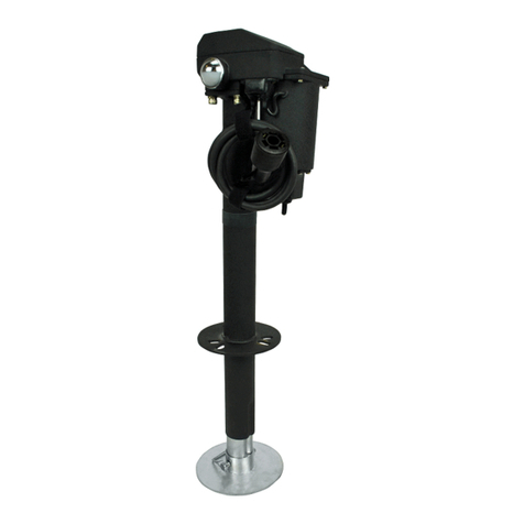
ULTRA 3502-7 ELECTRIC TONGUE JACK with 7-WAY PLUG
P/N 38-944037
US PATENT 9,821,774 B1
Rev 05.15.19
INSTALLATION/OPERATION
APPLICATION
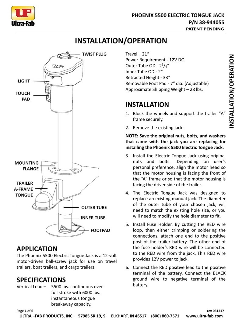
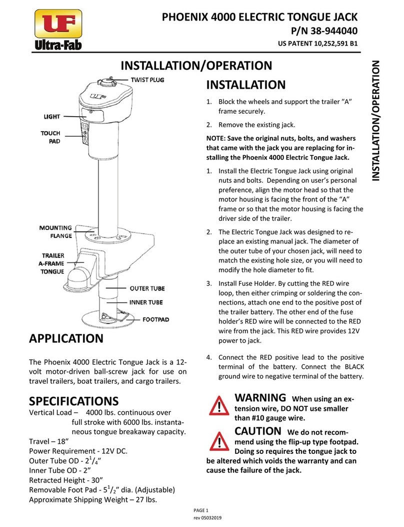
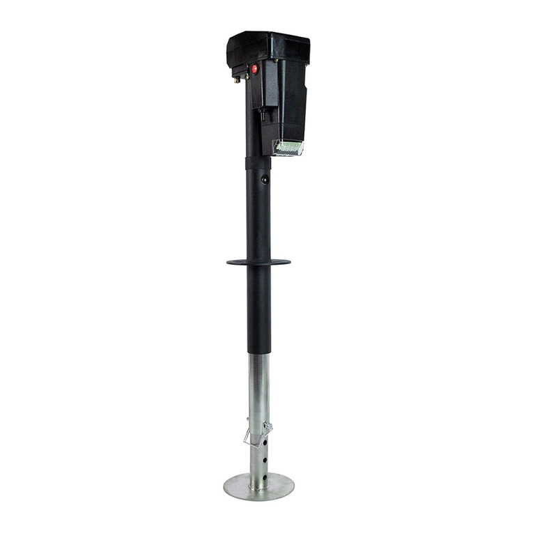
The Ultra 3502-7 Electric Tongue Jack with the 7-Way
Connector is a 12-volt motor- driven screw jack for use on
travel trailers and boat trailers.
SPECIFICATIONS
Vertical Load: 3500 lbs. continuous over full stroke with
5000 instantaneous tongue breakaway capacity.
Travel – 18″
Power Requirement -12 volt D.C.
Model # 3502 - 2″outer tube w/ 13/4″inner tube
Retracted Height - 251/2″
Removable Foot Pad -6″dia.
Approximate Shipping Weight – 22 lbs.
INSTALLATION
1. Block the wheels and support the trailer ″A″frame
securely.
2. Remove the existing jack.
NOTE: Save the original nuts, bolts, and washers for
installing the Ultra 3502-7 Electric Tongue Jack.
3. The Electric Tongue Jack was designed to replace an
existing crank down jack. The diameter of the outer
tube of your chosen jack, will need to match the
existing hole size, or you will need to modify the hole
diameter to fit.
4. Depending on user’s personal preference, align the
motor head so that the motor housing is facing the
front of the ″A″frame or so the motor housing is facing
the driver side of the trailer.
5. Insert 7-way plug into the 7-way receptacle on tow
vehicle.
WARNING: DO-NOT use extension wire.
CAUTION: We do not recommend using the flip-up type
footpad. Doing so requires the tongue jack to be altered which
voids the warranty and can cause the failure of the jack.
OPERATION
1. Block trailer wheels securely.
2. Plug the Tongue Jack 7-Way connector into the 7-way
male receptacle on the tow vehicle (after disconnecting
your trailer 7-Way connector).
3. The Ultra 3502-7 Electric Tongue Jack is operated by
means of the Toggle Switch located under the motor
housing.
4. Extend the jack by holding the Toggle Switch in the
Extend position.
CAUTION: The motor will stall if jack reaches the full
extent of travel both in retract and extend directions.
There is an over load protection for the jack to shut off
power that will auto reset in 15 seconds. After using jack,
operator should learn the travel limit stops. The operator
should stop the jack before reaching the travel limit.
5. Retract the jack by holding the Toggle Switch in the
Retract position. The jack is now fully retracted.
NOTE: If the motor should stall with the jack in the fully
retracted position, and the Toggle Switch is not released,
the motor will automatically switch off.
TROUBLESHOOTING: If you find the jack will not run, check
to see if the lights to the jack turn on. If the lights do not
turn on, the jack is not getting po wer.
1. Please check to make sure the CHARGE LINE from the
tow vehicle is “hot” to the tow vehicle 7-way receptacle.
Check the owner’s manual of the tow vehicle to find the
location of the fuse for the charge line to 7-way receptacle.
Usually it is under the hood. Make sure the tow vehicle
charge line is hooked up to the 7-way receptacle of the tow
vehicle.
2. The 7-way plug to the jack may have a piece of plastic
covering the connection left over from the creation of the
plug – use a pocket knife to scrape away the plastic.
3. The tow vehicle may need to be running to make the
charge line hot.
MANUAL OPERATION
1. Disconnect the 7-Way connector from the tow vehicle.
2. Remove plug cap in the access hole. (located top center
of the housing cover)
3. Insert the 9/16” deep well socket (included) in the
access hole, over the drive spindle tang. Rotate the
socket clockwise to retract and counter clockwise
extend.
4. When complete, remove socket and replace plug cap.
INSTALLATION/OPERATION

ULTRA 3502-7 ELECTRIC TONGUE JACK with 7-WAY PLUG
P/N 38-944037
US PATENT 9,821,774 B1
Rev 05.15.19
LUBRICATION
1. The jack is lubricated before leaving the factory. Under
normal conditions, lubrication will be needed annually.
2. Grease the Jackscrew by extending the jack until the
grease fitting is aligned with the hole in the outer tube.
Using a standard grease gun and standard chassis lube,
give two pumps.
3. Grease the gears in gearbox.
a. Disconnect the 7-Way Connector from the tow
vehicle.
b. Remove the gear cover via 4 Phillips screws.
c. Grease the gears with chassis lube and reinstall
cover.
STORAGE
A hook and loop strap has been included to help store the
wire/connector to the jack when not in us
MOTOR EXPLODED VIEW
No.
Part No.
Description
Q'ty
1
38-751030
Gear Housing Cover
1
2
38-751124
Pinion Gear 12T
1
3
38-751154
Pinion Key 3x6
1
4
38-751118
Spur Gear
1
5
38-101283
Circuit Breaker
1
6
38-751040
Motor
1
7
38-751037
Motor Switch
1
8
38-751047
Switch Housing
1
9
38-751039
Switch Boot
1
10
38-751060
Screw M4x8
6
11
38-751048
Motor Housing
1
12
38-751010
Screw M4x12
4
13
38-751042
Light
2
14
38-751057
Light Switch
1
15
38-751085
Main Gear
1
16
38-751070
Screw M4x16
4
17
38-751114
Rubber Plug
1
18 38-751090
7-Way Connector
Assembly
1
19 38-751091 Strap-Hook/Loop 1
Not Shown
Part No.
Description
Q'ty
38-751167
Socket 9/16” Deep
Well / Manual
Override
1

ULTRA 3502-7 ELECTRIC TONGUE JACK with 7-WAY PLUG
P/N 38-944037
US PATENT 9,821,774 B1
Rev 05.15.19
LOWER STEM ASSEMBLY EXPLODED VIEW
38-751170 – Lower Stem Assembly (Includes #1 & #2)
No.
Part No.
Description
Q'ty
1
38-752010
2" Outer Tube
1
2(A-F)
38-751160
1.75" Inner Tube Assembly
1
2A
38-751122
Collar Hex Head
1
2B
38-752018
Retaining Pin
1
2C
38-751121
Thrust Bearing
1
2D
38-751138
Cotter Pin
1
2E
38-751127
Upper Pin
1
2F
17-753230
Grease Zerk 6-1.0mm
1
3 38-751100
Footpad Standard 2”
(3502)
1
4
38-141023
Wire Lock Pin
1

ULTRA 3502-7 ELECTRIC TONGUE JACK with 7-WAY PLUG
P/N 38-944037
US PATENT 9,821,774 B1
Rev 05.15.19
WIRING DIAGRAM

ULTRA 3502-7 ELECTRIC TONGUE JACK with 7-WAY PLUG
P/N 38-944037
US PATENT 9,821,774 B1
Rev 05.15.19
T
TW
WO
O-
-Y
YE
EA
AR
R
L
LI
IM
MI
IT
TE
ED
D
W
WA
AR
RR
RA
AN
NT
TY
Y
ULTRA 3502/3502-7/4000/4002 TONGUE JACKS
THE MANUFACTURER NAMED BELOW MAKES THE FOLLOWING
WARRANTY WITH RESPECT TO THE ABOVE ULTRA-FAB PRODUCTS
1. This Warranty is made only to the first Purchaser (hereinafter called the “Original Purchaser”) who acquires this product for their own use.
2. This Warranty will be in effect for two years from the date of purchase by the Original Purchaser. It is suggested that the Original Purchaser
retain a copy of the dated bill of sale as proof of the date of purchase.
3. This Warranty covers only specified parts which shall be free from defects in material and workmanship under normal use. This Warranty
does not cover conditions unrelated to the material and workmanship of the product. Such unrelated conditions include, but are not limited
to (a) faulty installation and any damage resulting from such; (b) the need for normal maintenance and any damage resulting from the failure
to provide such maintenance; (c) failure to follow Manufacturer’s instructions for use of this product, and (d) any accident to, or misuse of, any
part of this product and any alteration by anyone other than the Manufacturer or its authorized representative.
4. In order to obtain the benefits of this Warranty, you should return the product which you find defective to the Manufacturer named below
during the period that this Warranty is in effect. All charges incurred in delivery of the product to the Manufacturer, and in picking it up after
the Warranty service has been completed, must be paid by the Original Purchas e r.
5. Any item returned in the manner described in paragraph 4 will be examined by the Manufacturer. If it is found that the returned item was
defective in material or workmanship, the Manufacturer will repair it without charge for material and labor.
6. Ultra-Fab will pay freight on replacement parts during the first 90 days of ownership by the Original Purchaser.
7. The Manufacturer does not authorize any person or company to create any Warranty obligation or liability on their behalf.
8. IN NO EVENT SHALL THE MANUFACTURER BE LIABLE FOR INCIDENTAL OR CONSEQUENTIAL DAMAGES. SOME STATES DO NOT ALLOW THE
EXCLUSION OR LIMITATION OF INCIDENTAL OR CONSEQUENTIAL DAMAGES SO THE ABOVE LIMITATION OR EXCLUSION MAY NOT APPLY TO YOU.
9. ANY IMPLIED WARRANTY, INCLUDING THE IMPLIED WARRANTY OF MERCHANTABILITY AND FITNESS FOR ANY PURPOSE, IS LIMITED TO THE
DURATION OF THIS LIMITED WARRANTY. SOME STATES DO NOT ALLOW LIMITATIONS ON HOW LONG AN IMPLIED WARRANTY LASTS, SO THE
ABOVE LIMITATION MAY NOT APPLY TO YOU.
10. THIS WARRANTY GIVES YOU SPECIFIC LEGAL RIGHTS, AND YOU MAY ALSO HAVE OTHER RIGHTS WHICH VARY FR0M STATE TO STATE.
57985 SR 19 S., Elkhart, IN 46517
Tel: (574) 294-7571 Fax: (574) 294-4980
www.ultra-fab.com
Table of contents
Other Ultra-Fab Jack manuals
Popular Jack manuals by other brands

Grizzly
Grizzly H8097 quick start guide

ATD Tools
ATD Tools ATD-7328 Operating instructions & parts manual

HEIN-WERNER AUTOMOTIVE
HEIN-WERNER AUTOMOTIVE HW93642W Operating instructions & parts manual

ATD Tools
ATD Tools ATD-7227B owner's manual

Tektronix
Tektronix Keithley HV-CS-1589 Installation information

SATA
SATA AE5822 user manual