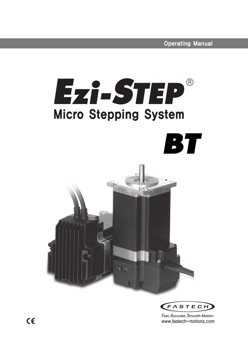
Fastech Ezi-servo plus-R User manual

www.fastech.co.kr
- User Manual -
Text (Ver.3)

www.fastech.co.kr
※Before operation ※
Thank you for your purchasing Ezi-SERVO.
Ezi-SERVO is an all-in-one Unit, for high-speed and high-precision drive of a stepping motor,
Ezi-SERVO is an unique drive that adopts a new control scheme owing to an on-board high-
performance 32 bit digital signal processor.
This manual describes handing, maintenance, repair, diagnosis and troubleshooting of Ezi-
SERVO.
Before operating Ezi-SERVO, thoroughly read this manual.
After reading the manual, keep the manual near the Ezi-SERVO so that any user can read the
manual whenever needed.

www.fastech.co.kr
- Table of Contents -
1. Safety Pre-caution ............................................................................................. 7
1.1 General Precaution ........................................................................................................................................7
1.2 Put the safety First.........................................................................................................................................7
1.3 Check the Product .........................................................................................................................................7
1.4 Installation .........................................................................................................................................................7
1.5 Connect Cables ............................................................................................................................................8
1.6 Operation...........................................................................................................................................................8
1.7 Check and Repair ...........................................................................................................................................8
2. Specifications of the Driver ............................................................................. 9
2.1 Driver Specification .......................................................................................................................................9
2.1.1 Ezi-SERVO Plus-R..................................................................................................................................9
2.1.2 Ezi-SERVO Plus-R MINI...................................................................................................................10
2.1.3 Ezi-SERVO ALL-28 series................................................................................................................ 11
2.1.4 Ezi-SERVO ALL-42/56 series.........................................................................................................12
2.1.5 Ezi-SERVO ALL-60/60-ABS series...............................................................................................13
2.2 Dimensions..................................................................................................................................................... 14
3. Specifications of the Motor...........................................................................16
3.1 Motor Specification.................................................................................................................................... 16
3.2 Motor Dimension ........................................................................................................................................ 17
3.3 Motor Torque ................................................................................................................................................20
3.3.1 Ezi-SERVO Plus-R............................................................................................................................... 20
3.3.2 Ezi-SERVO Plus-R MINI...................................................................................................................21
3.3.3 Ezi-SERVO Plus-R ALL series ........................................................................................................21
4. Configuration of the System .........................................................................22
4.1 Part Numbering ........................................................................................................................................... 22
4.2 System Configuration................................................................................................................................24
4.2.1 Ezi-SERVO Plus-R............................................................................................................................... 24

www.fastech.co.kr
4.2.2 Ezi-SERVO Plus-R 86mm series .................................................................................................. 24
4.2.3 Ezi-SERVO Plus-R MINI...................................................................................................................25
4.2.4 Ezi-SERVO ALL-28 series................................................................................................................ 25
4.2.5 Ezi-SERVO ALL-42/56 series.........................................................................................................26
4.2.6 Ezi-SERVO ALL-60/60-ABS series...............................................................................................26
4.3 External Wiring Diagram..........................................................................................................................27
4.3.1 Ezi-SERVO Plus-R............................................................................................................................... 27
4.3.2 Ezi-SERVO Plus-R 86mm................................................................................................................28
4.3.3 Ezi-SERVO Plus-R MINI...................................................................................................................29
4.3.4 Ezi-SERVO ALL-28 series................................................................................................................ 30
4.3.5 Ezi-SERVO ALL-42/56 series.........................................................................................................31
4.3.6 Ezi-SERVO ALL-60 series................................................................................................................ 32
4.3.7 Ezi-SERVO ALL-60-ABS ................................................................................................................... 33
5. Setting and Operation ....................................................................................34
5.1 Ezi-SERVO Plus-R ........................................................................................................................................ 34
5.2 Ezi-SERVO Plus-R MINI............................................................................................................................. 39
5.3 Ezi-SERVO ALL-28 .......................................................................................................................................42
5.4 Ezi-SERVO ALL-42/56 ................................................................................................................................45
5.5 Ezi-SERVO ALL-60/60-ABS series......................................................................................................... 48
6. Control Input/Output Signal .........................................................................52
6.1 Ezi-SERVO Plus-R series ........................................................................................................................... 52
6.1.1 Input ........................................................................................................................................................52
6.1.2 Output .................................................................................................................................................... 52
6.2 Ezi-SERVO ALL-28/42/56 series............................................................................................................ 53
6.2.1 Input ........................................................................................................................................................53
6.2.2 Output .................................................................................................................................................... 54
6.3 Ezi-SERVO ALL-60/60-ABS series......................................................................................................... 55

www.fastech.co.kr
6.3.1 Input ........................................................................................................................................................55
6.3.2 Output .................................................................................................................................................... 55
6.4 External Brake Connection...................................................................................................................... 56
6.5 Connection Circuit ...................................................................................................................................... 57
6.6 Input Signal.................................................................................................................................................... 59
6.6.1 ‘Limit’ Sensor and ‘Origin’ Sensor input................................................................................. 59
6.6.2 Clear Pos(Position Reset) input...................................................................................................59
6.6.3 Position Table A0~A7 (PT A0~A7) input................................................................................ 59
6.6.4 Position Table Start (PT Start) input ......................................................................................... 60
6.6.5 Stop input ............................................................................................................................................. 61
6.6.6 JOG+ and JOG- input .....................................................................................................................61
6.6.7 Servo ON and AlarmReset input ............................................................................................... 62
6.6.8 Pause input........................................................................................................................................... 62
6.6.9 Origin Search input ..........................................................................................................................63
6.6.10 Teaching input ....................................................................................................................................63
6.6.11 E-Stop input......................................................................................................................................... 64
6.6.12 JPT Input0~Input2 (Jump Position Table Input) input .....................................................65
6.6.13 JPT(Jump Position Table) Start input ........................................................................................66
6.7 Output Signal................................................................................................................................................ 67
6.7.1 Compare Out(Trigger Pulse) output .........................................................................................67
6.7.2 Inposition output...............................................................................................................................67
6.7.3 Alarm and AlarmBlink output...................................................................................................... 67
6.7.4 ACK and End output........................................................................................................................ 68
6.7.5 Moving and Acc/Dec output ....................................................................................................... 69
6.7.6 Org Search OK output .................................................................................................................... 69
6.7.7 Servo Ready output .........................................................................................................................69

www.fastech.co.kr
6.7.8 PT(Position Table) Output 0~2 output .................................................................................... 69
6.7.9 BRAKE+ and BRAKE- output........................................................................................................ 70
7. Operation...........................................................................................................71
7.1 Basic subject of Operation...................................................................................................................... 71
7.2 JOG Operation.............................................................................................................................................. 73
7.3 Position Operation...................................................................................................................................... 73
7.4 Origin Return................................................................................................................................................. 75
7.4.1 Common Origin Operation........................................................................................................... 76
7.4.2 Z-pulse Origin Operation ..............................................................................................................77
7.4.3 Limit Origin Operation.................................................................................................................... 78
7.4.4 Torque Origin Operation................................................................................................................ 79
7.4.5 Torque-Z Origin Operation ...........................................................................................................80
7.4.6 Set Origin Operation ....................................................................................................................... 80
7.5 Trigger Pulse Output ................................................................................................................................. 81
7.6 Push Motion .................................................................................................................................................. 82
8. Communication Function ...............................................................................87
8.1 Connection with the PC ...........................................................................................................................87
8.2 Communication Interface Circuit ......................................................................................................... 89
9. Protective Function..........................................................................................90
9.1 Alarm Type ..................................................................................................................................................... 90
9.2 Acquiring Alarm Information................................................................................................................. 91
9.3 Alarm Check and Release........................................................................................................................ 92
10. Parameter ..........................................................................................................93
10.1 Parameter List ............................................................................................................................................... 93
10.2 Encoder Setup .............................................................................................................................................. 94
10.3 Parameter Description...............................................................................................................................95

1.1. General Precaution
7
www.fastech.co.kr
1. Safety Pre-caution
1.1 General Precaution
Contents of this manual are subject to change without prior notice for functional improvement,
change of specifications or user’s better understanding.
When the manual is damaged or lost, please contact with FASTECH’s agents or our company at the
address on the last page of the manual.
Our company is not responsible for a product breakdown due to user’s dismantling for the product,
and such a breakdown is not guaranteed by the warranty.
1.2 Put the safety First
Before installation, operation and repairing the Ezi-SERVO thoroughly read the manual and fully
understand the contents. Before operating Ezi-SERVO please understand the mechanical
characteristics of the Ezi-SERVO and related safety information and precaution .
This manual divides safely precautions into Attention and Warning.
Attention
If user does not properly handle the product, the user may seriously or slightly
injured and damages may occur in the machine.
Warning
If user does not properly handle the product, a dangerous situation (such as an
electric shock) may occur resulting in death or serious injuries.
Although precaution is only a Attention, a serious result could be caused depending on the situation,
Follow safely precautions.
1.3 Check the Product
Attention
Check the product is damaged or parts are missing. Otherwise the machine
may get damaged or the user may get injured.
1.4 Installation
Attention
Carefully move the Ezi-SERVO. Otherwise, the product may get damaged
or user’s foot may get injured by dropping the product.
Use non-flammable materials such as metal in the place where the Ezi-
SERVO is to be installed. Otherwise, a fire may occur.
When installing several Ezi-SERVO in a sealed place, install a cooling fan
to keep the ambient temperature of the Ezi-SERVO as 50℃or lower.
Otherwise, a fire or other kinds of accidents may occur due to overheating.
Warning
The process of installation, connection, operation, checking and repairing
should be done with qualified person. Otherwise, a fire or other kinds of
accidents may occur.,

1.5. Connect Cables
www.fastech.co.kr
8
1.5 Connect Cables
Attention
Keep the rated range of Input Voltage for Ezi-SERVO. Otherwise, a fire or
other kinds of accidents may occur.
Cable connection should follow the wiring diagram. Otherwise, a fire or
other kinds of accidents may occur.
Warning
Before connecting cables check if input power OFF. Otherwise, an electric
shock or a fire may occur.
The case of Ezi-SERVO is insulated from the ground of the internal circuit
by the condenser. Ground the Ezi-SERVO. Otherwise, an electric shock or
a fire may occur.
1.6 Operation
Attention
If a protection function(alarm) occurs, firstly remove its cause and then
release(alarm reset) the protection function. If you operate continuously
without removing its cause, the machine get damaged or the user may get
injured.
Do not make Motor Free and make input signal to ON during operation.
Motor will stop and stop current will become zero. The machine may get
damaged or the user may get injured.
All parameter values are set by default factory setting value. Change this
value after reading this manual thoroughly. Otherwise, the machine may get
damaged or other kinds of accidents may occur.
1.7 Check and Repair
Warning
Stop to supply power to the main circuit and wait for a while before checking
or repairing the Ezi-SERVO. Electricity remaining in the capacitor may occur
danger.
Do not change cabling while power is being supplied. Otherwise, the user
may get injured or the product may get damaged.
Do not reconstruct the Ezi-SERVO. Otherwise, an electric shock may occur
or the reconstructed product can not get after service.

2.1. Driver Specification
9
www.fastech.co.kr
2. Specifications of the Driver
2.1 Driver Specification
2.1.1 Ezi-SERVO Plus-R

2.1. Driver Specification
www.fastech.co.kr
10
2.1.2 Ezi-SERVO Plus-R MINI

2.1. Driver Specification
11
www.fastech.co.kr
2.1.3 Ezi-SERVO ALL-28 series

2.1. Driver Specification
www.fastech.co.kr
12
2.1.4 Ezi-SERVO ALL-42/56 series

2.1. Driver Specification
13
www.fastech.co.kr
2.1.5 Ezi-SERVO ALL-60/60-ABS series

2.2. Dimensions
www.fastech.co.kr
14
2.2 Dimensions
1) Ezi-SERVO Plus-R
2) Ezi-SERVO Plus-R MINI
3) Ezi-SERVO ALL-28 series

2.2. Dimensions
15
www.fastech.co.kr
4) Ezi-SERVO ALL-42 series
5) Ezi-SERVO ALL-56 series
6) Ezi-SERVO ALL-60 series
7) Ezi-SERVO ALL-60-ABS series

3.1. Motor Specification
www.fastech.co.kr
16
3. Specifications of the Motor
3.1 Motor Specification

3.2. Motor Dimension
17
www.fastech.co.kr
3.2 Motor Dimension

3.2. Motor Dimension
www.fastech.co.kr
18

3.2. Motor Dimension
19
www.fastech.co.kr

3.3. Motor Torque
www.fastech.co.kr
20
3.3 Motor Torque
3.3.1 Ezi-SERVO Plus-R
Other manuals for Ezi-servo plus-R
2
This manual suits for next models
2
Table of contents
Other Fastech DC Drive manuals
Popular DC Drive manuals by other brands
YASKAWA
YASKAWA PROFINET V1000 Basic user's guide

SOMFY
SOMFY sonesse 30 rts instructions
Danfoss
Danfoss VLT AutomationDrive FC 302 with Connectors installation instructions
YASKAWA
YASKAWA SGDV user manual
Allen-Bradley
Allen-Bradley PowerFlex 70 Enhanced Control Reference manual

Pilz
Pilz PMCprimo Drive2 installation manual
