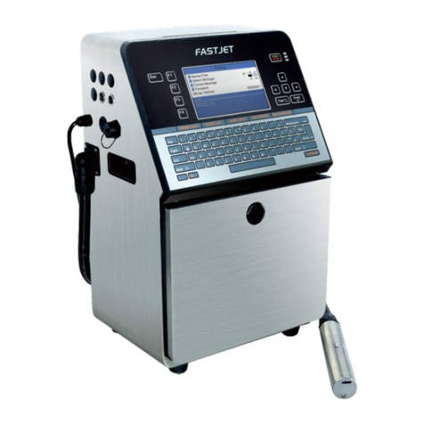
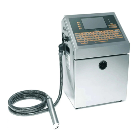
Fastjet A400 Series User manual


Contents
Chapter 1. Product Overview 1.........................................................
1.1 Main parts 1.....................................................................
1.2 Control Panel 2..................................................................
1.3 Print Head 3.....................................................................
1.4 Ink Compartment 4.............................................................
1.5 Main Screen 5...................................................................
1.6 Menu Description 6.............................................................
1.6.1 Message menu 6.........................................................
1.6.2 Editor 6...................................................................
1.6.3 User Fields 7.............................................................
1.6.4 Password 8...............................................................
1.6.5 System 9.................................................................
1.6.6 Configuration 10........................................................
1.6.7 Data 11...................................................................
1.7 Specifications 12................................................................
1.7.1 Electrical Specification 12............................................
1.7.2 Weight 12................................................................
1.7.3 Dimensions 12...........................................................
1.7.4 Environmental Specifications 12.....................................
Chapter 2. Printer Operation 13........................................................
2.1. Introduction 13................................................................
2.2. Installation method used for the first time 13............................
2.2.1 Manually Ink Injection 13.............................................
2.2.2 Exhaust the air of Pipe System 15....................................
2.3 Start Print 16....................................................................
2.3.1 Start Jet 16..............................................................
2.3.2 Ink line Observation 17................................................

2.3.3 Split Point Observation 18.............................................
2.4 Turn off the Printer 19.........................................................
2.4.1 Clean Stop Normally 19................................................
2.4.2 Clean stop (Power failure during the usage) 19....................
2.4.3 Clean stop (long term shutdown) 19.................................
2.5 Message 20.......................................................................
2.5.1 Create a Message 20...................................................
2.6 User Field 21....................................................................
2.6.1 Time 21...................................................................
2.6.2 Two-dimensional Code and Barcode 22..............................
2.6.3 Counter 23...............................................................
2.6.4 Logo 24...................................................................
2.6.5 Multiple user fields to generate a barcode 25.....................
2.7 Message Parameters 26........................................................
2.8 Print Configuration 28.........................................................
2.8.1 Limited print times configuration 28................................
2.8.2 Continuous Print 31.....................................................
2.8.3 Meter Mode 33..........................................................
2.8.4 Reverse Mode 34........................................................
Chapter 3. Trouble Shooting and Maintenance 37...................................
3.1 Diagnostic screen 37...........................................................
3.2 Fault and Warning Icon 38.....................................................
3.3 Trouble Shooting 40............................................................
3.4 Nozzle Cleaning 41.............................................................
3.5 Ink Line Adjustment 42........................................................
3.6 Draining Ink 43..................................................................
3.7 Pipe cleaning 44................................................................
3.8 Shaft Encoder and Photocell Connection 45................................
3.8.1 Photocell Connection 45..............................................
3.8.2 Shaft Encoder Connection 45.........................................

Chapter 1. Product Overview
1.1 Main parts
Major parts of A400 Inkjet Printer are as follows:
Figure 1-1. Main parts of the printer
1. Main Power Switch
2. Connector Panel
3. Umbilical
4. Print Head
5. Ink Compartment
6. Control Panel
7. Electronics Compartment
1

1.2 Control Panel
Figure 1-2: Control Panel
1. Function Keys
2. Information Key
3. Keypad
4. Arrow Keys
5. Status LEDs
6. Display
2

1.3 Print Head
Figure 1-3: Print Head
1. Front Cover of Print Head
2. Electrode of High Voltage Deflection Plate
3. Phase Detector
4. Charge Electrode
5. Heating Block Assembly
6. Rear Cover of Print Head
7. Valves
8. Nozzle Assembly
9. Gutter
3

1.4 Ink Compartment
Figure 1-4: Ink Compartment
1. Ink Tank
2. Solvent Tank
3. Cleaning Pump
4. Cleaning Filter
5. Filter before print head
6. Primary Filter
7. Pressure Buffer
8. Drainage Pipe
9. Filter before pump
10.Valves
4

1.5 Main Screen
Figure 1-5: Main Screen
1. Menus
2. Function Keys
3. Printer Status
4. the Name and the Content of the Message
5. Product Counter
6. Fault and Alarm Icons
This screen displays the following elements:
●The function key controls.
●The icons that indicate the printer status and fault conditions.
●The name and the content of the message. The content is the display
is an accurate representation of the current printing message.
1
2
3
4
5
6
5

1.6 Menu Description
1.6.1 Message menu
Table 1-1. Message menu
1.6.2 Editor
The commands in the Editor menu are shown only if the Message Editor or
the Logo Editor is open.
Table 1-2. Editor menu when edit message"
Message menu
Function
New Message
Open the New Message interface to create a new
message.
Edit Message
Edit a selected internal message.
Select Message
Select a message to print.
Message Parameters
Change parameter of the current print message
Delete Message
Delete the selected internal message.
Copy Message
Copy a saved message and rename it.
Delete All Message
Delete all saved message
Editor menu
Function
Select Font
Open the select font menu. The selected font is applied
to the next input text in the message.
Insert User
Filed
Selects user field to copy into the message.
Save Message
Save the message being edited to memory and keep the
editor screen open.
Save and Exit
Save the message being edited to memory and exit the
editor screen.
Clear Message
Delete the content in the message and keep the editor
screen open.
Abandon
Exit the editor screen without saving changes to the
message.
6

Table 1-3. Editor menu when edit logo
1.6.3 User Fields
Table 1-4. User Fields menu
Editor menu
Function
Set Logo Size
Change the size of the logo.
Save Logo
Save the logo to the memory and keep the editor screen
open.
Save and Exit
Save the logo to the memory and exit the editor screen.
Clear Logo
Removes the edited logo.
Abandon
Exit the editor screen without saving logo to memory.
User Fields menu
Function
Edit User Field
Edit an internal user field, such as Time, Counter,
Logo, Text, External Data, Barcode.
New User Field
Open New User Field interface and edit it.
Delete User Field
Delete the selected internal user field.
Reset Counter
Select counter and reset it.
Set Shifts
Set the starting and ending time of each shift
7

1.6.4 Password
Table 1-5. Password menu
Password menu
Function
Enter User Password
Enter user password for advanced operating
authority.
Change User Password
Enter a new user password to change user
password.
Set Password Levels
Open the Set Password Level menu.
This has options for the Main Screen and each of
the menus. You can set “On” or “Off” for each
option available in the menu. “Off” doesn’t
have password protection.
Enter Maintain Password
Enter maintain password for maintenance
authority.
Change Maintain
Password
Enter a new maintain password to change
maintain password.
Clear Password
Clear password to the lowest authority.
8

1.6.5 System
Table 1-6. System menu
System menu
Function
Clean Start Jet
Start the ink jet. A flush and bleed sequence is
performed to prevent unstable ink line while
ejecting from nozzle.
Quick Start Jet
Quick start the ink jet without a flushing sequence.
Clean Stop Jet
Stop the ink jet. Clean the nozzle and related
pipes.
Quick Stop Jet
Quick stop the ink jet without a flushing sequence.
Nozzle Flush
Clean nozzle with solvent manually
Umbilical Purge
Clean the umbilical. It can be used to install the
inkjet printer to exhaust air.
Charge Fault
Shutdown
This Function can turn off the automatic stopping
jet when charge fault.
Gutter Fault
Shutdown
This Function can turn off the automatic stopping
jet when gutter fault.
Rolling Phase Disable
Disable/Enable rolling phase.
Debug
Turn on/turn off each valve and main pump
separately.
Gutter Mode
Set gutter mode Continuous or Intermittent.
System Flush Purge
Clean and drainage Ink System
Wash Nozzle
The nozzle orifice is cleaned by the application of
solvent and a suction action.
9

1.6.6 Configuration
Table 1-7. Configure menu
Configure menu
Function
Heater Set Point
Set nozzle temperature(0 to 40 ℃)
Set Running Pressure
Set pump pressure (0 to 450 Pa)
VMS Calibration
It is able to set the viscosity of ink manual/auto.
Modulation Set Level
Set modulation value.
Phase Charge Set
Set phase charge value.
Phase Offset Set
Set phase offset value.
Charge Value
Set charge value.
EHT Trip Level Set
Set EHT trip level.
LCD Contrast
Set the contrast of the LCD.
Set Time/date
Set the Real Time Clock(RTC) in the printer to the
local time and date.
Pressure Zero Offset
Pump zero adjustment.
EHT Range Set
Set EHT value of each grade.
Set Ink Type
Select the ink type.
Speed Ratio
Set character width ratio/print delay ratio/
Internal Interval ratio/External Interval ratio.
Serial Port
Configuration
Serial port configuration
10

1.6.7 Data
Ta b l e 1 - 8 . D a t a menu
Data menu
Function
Status
Display each of current status of the printer.
Diagnostic Screen
All current operational monitoring data of the
printer which are conductive to diagnose
malfunctions.
Product Counter
It can be used to reset counter.
Software No.
Display software version.
Set Language
Set the type of menu language.
Maintain Time
Display printer running time and maintain time.
Msg Copy to USB
Copy internal message to U disk.
Logo Copy to USB
Copy internal Logo to U disk.
Copy Msg From USB
Copy message in U disk to memory.
Copy Logo From USB
Copy Logo in U disk to memory. Support
monochrome bitmap file format(.bmp).
11

1.7 Specifications
1.7.1 Electrical Specification
The electrical specifications of the printer are shown in Table 1-9.
Table 1-9. Electrical specifications
1.7.2 Weight
The net weight specifications of the printer are shown in Table 1-10.
Table 1-10. Weight specification.
1.7.3 Dimensions
The dimensions of the printer are shown in Table 1-11.
Table 1-11. Printer Dimensions
1.7.4 Environmental Specifications
The environmental specifications of the printer are shown in Table 1-12.
Table 1-12. Environmental Specifications."
Voltage
100V AC - 240V AC
Frequency
50Hz to60Hz
Power Consumption
90 watts Maximum
Net Weight
27kg
Cabinet
460L*230W*565H
Diameter of the Print Head
35mm
Length of the Print Head
262mm
Diameter of the nozzle orifice
70µm/60µm/50µm/40µm
Length of the Umbilical
3m
Operating temperature
5℃to 45℃(41℉to 113℉)
Rate of change of ambient
temperature
10℃(18℉) per hour maximum
Relative humidity
0% to 90% non-condensing
Storage temperature
5℃to 45℃(41℉to 113℉) in
original packaging
12

Chapter 2. Printer Operation
2.1. Introduction
This chapter provides the procedures to do the following tasks:
●Installation method used for the first time
●Start print
●Tu r n o f f t h e p r i n t e r
●Manage message
●Manage user field
●Print configuration
2.2. Installation method used for the first time
2.2.1 Manually Ink Injection
Inject ink into pipe system in order to exhausting the air. Because the pipe
system is full of air, when the printer is first install.
The procedures are as follow:
1. Turn on the printer. Open the door of ink Compartment. Pull the pipe
system out.
2. Inject ink into the mixer tank according to the following figure(Figure
2-1).
13

Figure2-1. How to inject ink into the mixer tank.
Notes
Stop injecting ink once the Main Screen display the Mixer Tank Full icon.
Stop injecting ink once the Diagnosis Screen Mixer High turn to ‘ON’.
Note
Please inject ink and solvent into ink tank and solvent tank separately
after ink injection successful.
Restore the dismounted screw. Then do exhausting operation.
14

2.2.2 Exhaust the air of Pipe System
Exhaust the air of the pipe system after manual ink injection.
The procedures are as follow:
1. Select the System menu using the Left/Right arrow key. Press the
Enter key.
2. Select the Debug menu and then press the Enter key. The interface
is as follow.
Figure 2- 2. Debug interface
3. Open the print head front cover. Put the special effluent bottle under
the print head to catch the waste ink
4. Open the Pump, V6, V11 and V12 in the Debug interface. Keep they
open for 3 minutes
5. Open V7, and keep it open for 15 seconds
6. Close V7,and keep it close for 30 seconds.
Repeat Step 5 and 6 once.
7. Exit Debug menu. Exhausting is over.
Note
When proceeding the third step, take out of the pressure buffer, keep the
arrow up, shake it gently, make the inside air discharge totally.
15

2.3 Start Print
2.3.1 Start Jet
To start the printing process, the following operations are required:
1. Make sure that the electrical supply for the printer is available.
2. Open the front cover of the print head, check on the components
inside the print head make sure that all components are clean and
dry.
3. Close the front cover of the print head. Press the main power switch
to turn on the printer.
4. Press the F1 key to start the jet start sequence. The starting
sequence takes approximately two minutes. The interface is as
follow:
Figure 2-3. Starting Interface
5. Monitor the icons on the display and the LEDs. When machine status
in the bottom display “Waiting Print”, the starting sequence is
completed. The interface is as follow:
Figure 2-4. Starting completed Interface
Note
If you start and stop the printer many times, the increased uses of makeup
fluid can inflect printing quality.
16

2.3.2 Ink line Observation
The ink spouts through the nozzle, and then recycles by the gutter after jet
starting.
Side View:
Figure 2-5. Side View of Ink line
Front View:
Figure 2-6. Side View of Ink line
17
Table of contents
Other Fastjet Printer manuals
