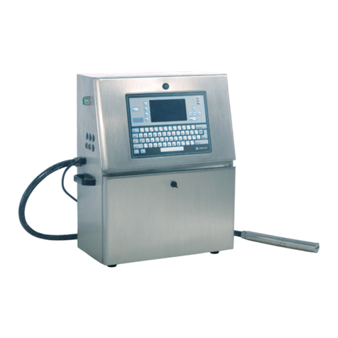
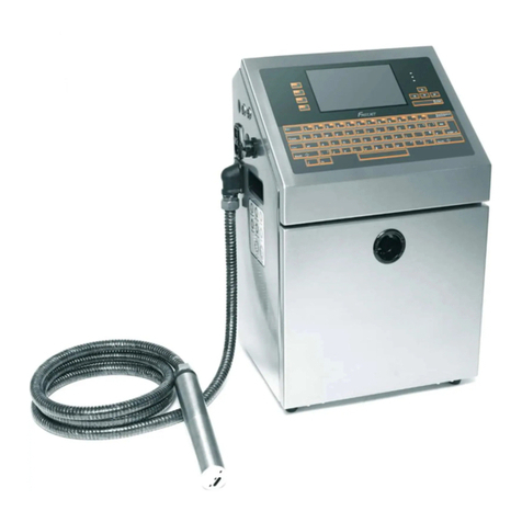
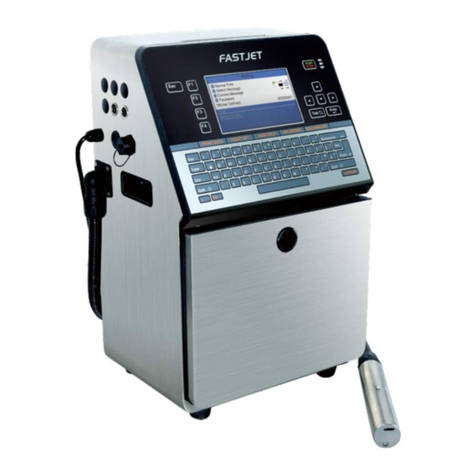
Fastjet F540 Series User manual

Inkjet Printer
Operation
Manual!
Apr 16th 2020 Edited V1.1
F540/560/560Plus Series

1. Safety Guidelines 1-------------------------------------
1.1 safety warning 1--------------------------------------------------------------------
1.2 Safety prevention 1----------------------------------------------------------------
1.3 Use 1----------------------------------------------------------------------------------
1.4 Handling 2----------------------------------------------------------------------------
1.5 Responsibility 2---------------------------------------------------------------------
2. Introduction 3---------------------------------------------
2.1 Appearance overview 3-----------------------------------------------------------
2.2 Control Panel 3---------------------------------------------------------------------
2.3 Printhead 4---------------------------------------------------------------------------
2.4 Ink Core 4----------------------------------------------------------------------------
2.5 Main Screen 5-----------------------------------------------------------------------
2.6 Menu Analysis 6--------------------------------------------------------------------
2.6.1 PRINT DATA 6---------------------------------------------------------------
2.6.2 USER FIELD 6--------------------------------------------------------------
2.6.3 PRINT SET 7----------------------------------------------------------------
2.6.4 INK SYSTEM 8--------------------------------------------------------------
2.6.5 MACHINE SET 9-----------------------------------------------------------
2.6.6 F4 Password 10-------------------------------------------------------------
2.6.7 W) User Defined 10--------------------------------------------------------
2.6.8 Photocell 1 Set 11----------------------------------------------------------
2.6.9 Photocell 2 Set 11----------------------------------------------------------
2.7 Specifications 12-------------------------------------------------------------------
3. Printer Operation 13------------------------------------
3.1 Commission(For F540/560/560Plus)13----------------------------------
3.2 Start The Printer 14----------------------------------------------------------------
3.2.1 Start Jet 14-------------------------------------------------------------------
Content

3.2.2 Inkjet Observation 15------------------------------------------------------
3.2.3 Drops Observation 16-----------------------------------------------------
3.3 Stop Jet 17---------------------------------------------------------------------------
3.3.1 Stop Jet and Clean 17-----------------------------------------------------
3.3.2 Stop and Clean (Power off during use of the printer) 17---------
3.3.3 Stop and Clean (long-term stop of use) 17--------------------------
3.4 Create Message 18----------------------------------------------------------------
3.4.1 Create a Sample Message 18-------------------------------------------
3.5 Create/Edit User Field 20-------------------------------------------------------
3.5.1 Time User Field 20--------------------------------------------------------
3.5.2 Additional remarks for time user field 21-----------------------------
3.5.3 Barcode User Field 22----------------------------------------------------
3.5.4 Additional remarks for Barcode User Field 23-----------------------
3.5.5 Counter User Field 24----------------------------------------------------
3.5.6 Instructions for Items in the Counter 25------------------------------
3.5.7 Logo User Field 26--------------------------------------------------------
3.5.8 Code User Field 28--------------------------------------------------------
3.5.9 External data User Field 29---------------------------------------------
3.6 Message Parameters 30--------------------------------------------------------
3.6.1 Modify message parameters and contents 30---------------------
3.7 Print Mode Setting 31------------------------------------------------------------
3.7.1 Single Printing Mode 31--------------------------------------------------
3.7.2 Continuous Printing Mode 32-------------------------------------------
3.7.3 Measure mode 33---------------------------------------------------------
3.7.4 Traverse Printing Mode 34----------------------------------------------
3.7.5 Repeat Printing Mode 35------------------------------------------------
4. Maintenance 36------------------------------------------
4.1 Diagnostic Screen 36-------------------------------------------------------------
Content

4.2 Failure and warning icons 37----------------------------------------------------
4.2.1 Failure icons 37-------------------------------------------------------------
4.2.2 Warning icons 38-----------------------------------------------------------
4.3 Troubleshooting 39----------------------------------------------------------------
4.4 Wash Nozzle 40--------------------------------------------------------------------
4.5 Ink Jet Alignment 40---------------------------------------------------------------
4.6 Drain( For F560Plus ) 41---------------------------------------------------------
4.7 Clean Ink System 41--------------------------------------------------------------
4.8 Sensor and Encoder Wiring Diagram 42-------------------------------------
4.8.1 Sensor Diagram 42---------------------------------------------------------
4.8.2 Encoder Diagram 42-------------------------------------------------------
4.9 Printer Stander 43------------------------------------------------------------------
Content

1. Safety Guidelines
1.1 safety warning
•Maintenance of this equipment must be performed by a maintenance
professional.
•When the printer is connected to the power supply and related circuits, a
lethal voltage is generated. Non-professionals cannot open the circuit
compartment, and cannot check and repair the circuit system.
•The consumables used in the printer may be flammable liquids. The use of
consumables must not only follow the Material Safety Data Sheet (MSDS)
instructions, but also the printer must be regularly inspected and maintained
to minimize safety hazards. (Note: The printer has an alarm function that has
been sent for maintenance time. Please pay attention to whether this
function is normal. If there is an alarm when the printer maintenance time
has expired, please notify the service engineer in time.)
1.2 Safety prevention
•The installation of the printer should be stable and well grounded .
•The printer must be installed in a ventilated place, away from heat, fire and
static electricity. No smoking near the printer.
•The container lid of the ink, solvent and cleaning agent used in the printer
should be tightly closed and stored in a ventilated environment away from
the printer.
•The printer should be kept clean, because the consumables used may be
flammable liquids, and the ink can burn after drying.
•Place a carbon dioxide dry powder fire extinguisher near the printer.
1.3 Use
•The printer is a non-contact inkjet device and is not suitable for all occasions
(such as explosive atmospheres). It should be used in accordance with
safety guidelines and provide a suitable working environment. Otherwise, the
consequences will be borne by the user.
Page 1

•It is recommended to use the original consumables (including inks, solvents,
cleaning agents, maintenance products, etc.) of the printer. You must obtain
the Material Safety Data Sheet (MSDS) from the dealer and read and follow
them carefully. Otherwise the consequences will be borne by the user.
•In operation, wear anti-ink gloves and safety glasses for those who may
touch the consumables.
1.4 Handling
•For machines with ink and solvent in the machine, non-vertical handling is
prohibited. If the printer cannot be kept in a vertical state, the ink and solvent
should be completely drain out before handling.
1.5 Responsibility
•Our company is not responsible for any consequences resulting from
violations of safety instructions, safety requirements and violations of basic
safety practices when using and maintaining the printer.!
Page 2

2. Introduction
2.1 Appearance overview
Introduction:!
1. Power button !
2. Upper:Electronics Compartment 、Control Panel !
3. Lower:Ink Compartment!
4. Connector Panel !
5. Umbilical !
2.2 Control Panel
Page 3
Right View
Front View
Left View

2.3 Printhead
2.4 Ink Core
""!
!
Ink Core(Front View) Ink Core(Back View)
Page 4
* Exhaust Air Switch
Condenser
Cover
Drain Pipe
* Exhaust Vent Plug
Manifold
Filter
Gear Pump
Flushing
Pump
*Gutter
Pump
*Please remove the exhaust vent plug and turn on exhaust
air switch before use.
*It’s Gutter Pump for F560Plus!
*It’s Addition Pump for F540/F560
Deflection Plate
Nozzle
Charge Electrode
Gutter Pipe
Phase Detector
Last Chance Filter
Nozzle connector

2.5 Main Screen
The main screen is the default screen after the printer powered on:!
Instructions:!
1. The current status description area of the device;!
2. A shortcut function keypad includes an user-defined function;!
3. The name of the current message ;!
4. The content of the current message, it’s a WYSIWYG message viewer, the
content of which is consistent with the content printed by the printer;!
5. The printer icon display area contains icons such as consumables, equipment
status, warnings and faults;!
6. The counter of the cumulative number of prints can be reset;#
Page 5
1
5
2
3
4
6

2.6 Menu Analysis
2.6.1 PRINT DATA
1. It is used to select and recall the stored messages , which is equivalent to the “F2
Select Message” on the main screen.!
2. Used to create and edit saved messages.!
3. Used to set the default message parameters.!
4. It is used to delete the messages stored in the printer.!
5. It is used to copy the messages in the printer to the USB storage device.!
6. It is used to copy the messages in the USB storage device into the printer.!
2.6.2 USER FIELD!
1. Used to create and edit saved user fields.!
2. Used to delete user fields that have been stored in the printer.!
3. Used to transfer the custom pattern in the printer to the USB storage device.!
4. Used to copy the picture files (BMP monochrome) in the USB storage device into the
printer.!
5. It is used to set the date and time code. For example, if January is printed as Jan, etc.,
in the time user field, the date and time code can be referenced by referring to a
specific letter, RR can refer to the year code, and SSS can refer to the month code, TT
can reference the day code, UU can reference the hour code, VV can reference the
minute code, some models do not include this function.#
Page 6

2.6.3 PRINT SET
1. Used to enable or disable the printing function. if set to "Disable", the printer will
disable the printing function and prompt "High voltage not activated" in the status bar.!
2. It is used to select the printing quality, standard and high quality 01~15. The higher the
high quality selection, the better the printing quality will be, but the slower the printing
speed will be.!
3. It is used to set whether the main screen “F1 Manual Start/Stop Printing” is effective. If
you need to use an external sensor such as an electric eye, you need to set this option
to “Disable ”.!
4. Photocell 1 Set, refer to 2.6.8 Photocell 1 setting submenu.!
5. Photocell 2 Set, refer to 2.6.9 Photocell 2 setting submenu.!
6. Set the encoder mode, you can set "internal", "external". When set to "External", it is
effective to use an encoder.!
7. Used to reset the counter used in the current message to any value within the counter
range.!
8. The product counter on the main screen can be reset to any value.!
9. It is used to set the printing mode of the printer, which can be set to “Single”, “Repeat”,
“Continuous” and “Traverse”.!
10. When the print mode is set to “Continuous”, use this menu to set “Internal Interval”
(valid when the shaft encoder is internal), “External Interval” (valid when the shaft
encoder is external) and “Measure” related options. !
11. When the print mode is set to “Repeat ”, use this menu to set the “Print times” to
control the print times per trigger.!
12. When the print mode is set to “Traverse”, use this menu to set the options for traverse
printing;!
13. It is used to set the ratio between the actual effective value and the set value of the
message width, delay and message interval. Default value is 1.#
Page 7

!
2.6.4 INK SYSTEM
1. Flushing the nozzle blockage automatically.!
2. After performing , open the printhead cover and use cleaning agent to clean the nozzle
manually. Refer to 4.4 Nozzle Cleaning for details.!
3. It is used to control the pump, valve and other parts separately.!
4. Used for cleaning umbilical , only for commissioning engineers to use when debugging.!
5. It is used to quickly start the jet.!
6. For quick stop inkjet without auto cleaning.!
7. For setting the ink type, built-in B600, 601, A630, 680, 619, 669, 2630, 2631 and 630.!
8. Used to set the ink viscosity, manual / auto optional;!
9. Used to calibrate the standard reference pressure;!
10. For the entire ink system cleaning, follow the on-screen instructions, refer to 4.7
System Cleaning;!
11. Used to exhaust the air, usually for commissioning.!
12. Open/Close the positive air to the printhead.!
13. It is used to fill the mixer tank with ink to the OK level. It is used when the machine is
first time use. (F540/F560 without this option).!
14. It is used to clean the umbilical. To perform this procedure, the nozzle connecting pipe
should be shorted.!
15. Use for fill ink for F560Plus, (F540/F560 without this option).#
Page 8
*
*

2.6.5 MACHINE SET
1. Used to disable the automatic shutdown caused by charge fault.!
2. Used to disable the automatic shutdown caused by the gutter fault.!
3. used to set the modulation value, manual/auto optional, auto mode only takes effect
during startup.!
4. Used to set the charge value.!
5. Used to set the running pressure.!
6. Used to set the heater target temperature.!
7. Used to set the phase charge value.!
8. Used to set the phase offset value.!
9. Used to check the current software information.!
10. Used to define the shortcut function on main screen.!
11. Used to enable /disable the keyboard buzzer.!
12. Used to set the system time and date;!
13. Used to set the extra high tension leakage alarm value.!
14. Used to set the output range of the 7KV extra high tension.!
15. Used to change the gutter mode.!
16. Used for serial port configuration.!
17. Used for Ethernet configuration.!
18. Used to set the printer language.!
19. Used to view equipment maintenance time.!
20. Turn offthe backlight protection, the screen is always bright, will shorten the screen life!
21. When the EHT Grade is High, the detection sensitivity is enhanced; When it is Low,
the detection sensitivity is reduced, and relevant safety prompts will pop up when the
power is turned on.#
Page 9

2.6.6 F4 Password
Only "Enter Password" menu is displayed before the password is entered.!
1. Used to enter password;!
2. Used to exit the password to level 0 (The lowest permission).!
3. Used to set the password protection level of each function of the system.!
4. Used to modify the user password;!
5. Used to modify the maintenance password;!
2.6.7 W) User Defined !
1. Users can customize frequently used functions to this area;#
Page 10

2.6.8 Photocell 1 Set
1. Select photocell 1 to be active by high or low level when triggering printing.!
2. The way of the external photocell triggers printing, Gate or Trigger optional .!
3. Within this time, the time interval between the trigger level and the trigger level can be
obtained again (such as avoiding secondary sensing in the same product);!
4. Select how to handle the photocell signal;!
5. Open/Close the secondary sensing prompt;!
6. Set the number of times the photocell is sensed before it is triggered effectively.!
7. This option is associated with the sixth “Signal Times” setting, and the first few times
within the set number of sensing times are valid;!
2.6.9 Photocell 2 Set
1. Select photocell 2 to be active by high or low level when triggering printing.!
2. Disable, Reset counter, Traversing print control , Reset traversing print , Opposite print
and Reset detection & counting are optional.!
3. The way of the external photocell triggers printing, Gate or Trigger are optional.#
Page 11

2.7 Specifications
Electrical specifications!
Weight!
Dimensions!
Environment specifications!
Page 12
Voltage
100V-240V AC
Frequency
50Hz-60Hz
Energy consumption
120(W) maximum value
Net weight
24KG
Cabinet
345L * 286W * 570H
Printhead diameter
41mm
Printhead length
260mm
Nozzle size
70,60,50,40 μm
Umbilical length
2700mm
Operating temperature
5℃to 45℃
Ambient temperature replacing
rate
10℃per hour at most
Relative humidity
0-90%, non-frosting
Storage temperature
5℃-45℃(original package)

3. Printer Operation
3.1 Commission(For F540/560/560Plus)
Printer needs to be filled with ink and exhaust air before use. !
1. Open the lower cabin door, pull out the ink system, and fill 500-750ml of ink into the
mixer tank with a beaker in the order of A. B.* C. D., as shown in figure:!
2. According to the label, install the correct ink and make-up cartridge to the correct
position, push the ink system into the cabin and close the lower cabin door .!
3. Connect the printer to an appropriate power source and power on the printer .!
4. Enter the INK SYSTEM menu and perform E) Exhaust Air program to complete
ink way priming. Screen prompt will advise when complete. NOTE: Ink will come from
the gutter, place a catcher under the printhead.
!
5. Clean the printhead.!
Page 13
* During normal use of the printer, the exhaust vent plug Aneeds to be removed, and the exhaust
air switch Bneeds to be opened , otherwise it will cause printer failure.
C. Remove the lid of the condenser
(Installed back after filling)
A. Remove the exhaust
air plug
!
!
D. Use a beaker to fill
500-750ml ink from the
condenser
B. The exhaust air switch must
be turned on before use.

3.2 Start The Printer
3.2.1 Start Jet
1. Connect the printer to an appropriate power source.!
2. Open the printer head cover, check various components in the printhead, and check
that various components are clean and dry.!
3. Put on the printhead cover, press the power button at the right side of the printer, and
wait for the screen to enter the main operation interface!
4. Press to start the program for about 4 minutes. The interface is as follows:!
5. Observe the status indicator and the main screen. When the green LED is lit, the
startup is completed. The interface is as follows:!
!
Page 14
*Frequent start/stop jet will cause the ink to be diluted, which will affect the printing quality .

3.2.2 Inkjet Observation
Side View :
Front View:!
Page 15
Charge
Electrode
Nozzle
Inkjet
The inkjet is at the central
position of the gutter pipe
Charge
Electrode
Nozzle
The inkjet is about 1/4 of the right side
of the gutter pipe

3.2.3 Drops Observation
The drops are generated after printer has started normally. It directly affects the printing
effect and printing durability. Good drops roughly depend on the following three factors:!
Appropriate and stable pressure!
Correct ink viscosity!
Correct modulation value!
The observation method is as follows:!
1. Take out the magnifying glass in the standard and place it on the red LED light about
15mm.!
2. Adjust the distance of the magnifying glass up and down slightly to observe the drops
shown in the figure below:!
3. The drops are disconnected at the middle of the charge electrode. The shape of the
drops before disconnection can refer to the following figure:#
Page 16
Pool conditions To be avoided Good
*The shape of drops can be adjusted through the "Modulation Set Level" in the MACHINE
SET menu;
This manual suits for next models
2
Table of contents
Other Fastjet Printer manuals
