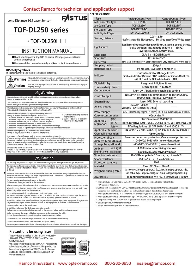
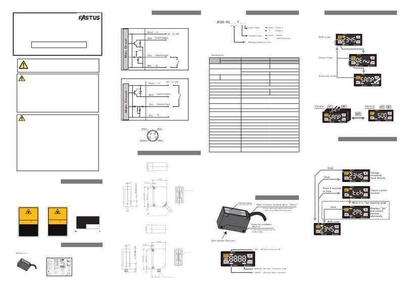
Fastus CDX Series User manual

OPTEX FA CO.,
LTD.
*FASTUS is a product brand of Optex FA.
High-Accuracy Laser Displacement Sensor
CDX Series
User’s Manual
Before using this product, please read this manual carefully.
Keep this manual at hand so that it can be used whenever necessary.
Store the manual in a safe location.
Got Application or Technical Questions?
Contact Ramco Innovations today!
Ramco - Optex FA Divsion www.Optex-Ramco.com Got Questions? 1-800-280-6933

Ramco - Optex FA Divsion www.Optex-Ramco.com Got Questions? 1-800-280-6933

i
Introduction
Introduction
Thank you for purchasing the CDX Series High-Accuracy Laser Displacement Sensor. This manual
contains the information necessary for using the CDX Series High-Accuracy Laser Displacement Sensor.
Read this manual thoroughly before using the product to ensure correct product use with full understanding
RIWKHIXQFWLRQVDQGSHUIRUPDQFHRIWKHSURGXFW$OVRDIWHU\RXKDYH¿QLVKHGUHDGLQJWKLVPDQXDOVWRUHLW
safely for future reference.
Trademarks and registered trademarks appearing in this manual are the property of their respective
owners.
The copyright of this user’s manual is owned by Optex FA Co., Ltd. All the contents contained herein are
protected by copyright law. Unauthorized copying of this manual is strictly prohibited.
Ramco - Optex FA Divsion www.Optex-Ramco.com Got Questions? 1-800-280-6933

ii Safety Precautions
Safety Precautions
This manual uses the following symbols to display safety precautions for ensuring safe operation of the CDX
Series high-accuracy laser displacement sensor.
Precautions listed here describe important information about safety. Make sure to follow them accordingly.
Safety Symbols
The safety symbols and their meanings are as follows.
Warning
Indicates that any improper operation or handling may result in moderate or minor injury,
and in rare cases, serious injury or death. Also indicates a risk of serious property
damage.
Caution
Indicates that any improper operation or handling may sometimes result in moderate or
minor injury or property damage.
Notes
Warning
This product cannot be used as protective equipment for the purpose of protecting the human
body.
Do not disassemble, repair, modify, deform under pressure, or attempt to incinerate this product.
'RLQJVRPD\FDXVHLQMXU\RU¿UH
Do not use this product in water or in a location where it may be exposed to water. Do not use
this product if wet.
'RLQJVRPD\FDXVHD¿UHRUGDPDJHWKHSURGXFW
7KLVSURGXFWLVQRWH[SORVLRQSURRIDQGVKRXOGQRWEHXVHGDURXQGÀDPPDEOHRUH[SORVLYHJDVHV
or liquids.
'RLQJVRPD\FDXVHLJQLWLRQUHVXOWLQJLQDQH[SORVLRQRU¿UH
'RQRWXVHDLUGXVWHUVRUDQ\VSUD\WKDWXVHVÀDPPDEOHJDVDURXQGWKHSURGXFWRURQWKHLQVLGH
of the product.
'RLQJVRPD\FDXVHLJQLWLRQUHVXOWLQJLQDQH[SORVLRQRU¿UH
Do not install this product or its cables in any of the following locations.
'RLQJVRPD\FDXVHD¿UHGDPDJHRUDPDOIXQFWLRQ
1. Locations where dust, salt, iron powders, or vapor (steam) is present.
/RFDWLRQVVXEMHFWHGWRFRUURVLYHJDVHVRUÀDPPDEOHJDVHV
3. Locations where water, oil, or chemical splashes may occur.
4. Locations where heavy vibrations or impacts may occur.
5. Locations where the ambient temperature exceeds the rated range.
6. Locations subject to rapid temperature changes (or where condensation occurs).
/RFDWLRQVZLWKVWURQJHOHFWULFRUPDJQHWLF¿HOGV
8. Outdoor locations or locations subject to direct light.
Do not use the product at voltages or with AC power supplies that exceed the rated voltage.
'RLQJVRPD\FDXVHD¿UHRUGDPDJHWKHSURGXFW
Ramco - Optex FA Divsion www.Optex-Ramco.com Got Questions? 1-800-280-6933

iii
Safety Precautions
Warning
What to do in the event of a malfunction such as smoke being emitted from the product
If you detect any malfunction including emission of smoke, abnormal smells or sounds, or the
body becoming very hot, immediately stop operating the product and turn off the power.
'RLQJVRPD\FDXVHD¿UH
Repairing the product is dangerous and should in no way be performed by the customer. Contact
an Optex FA sales representative for repairs.
What to do if water enters the product
If water or any other liquid enters the product or the cable, immediately stop operating the
SURGXFWDQGWXUQRIIWKHSRZHU8VLQJWKHSURGXFWLQWKLVFRQGLWLRQPD\FDXVHD¿UH
Caution
Do not touch the product or the cable with wet hands. Doing so may damage the product.
)ROORZWKHLQVWUXFWLRQVLQWKLVPDQXDORUWKHVSHFL¿HGLQVWUXFWLRQPDQXDOZKHQZLULQJWKHSURGXFW
or the dedicated controller for the correct wiring method.
Incorrect wiring can damage the product or the controller, or cause a malfunction.
Use the dedicated cable for connecting the product.
Use of anything other than the dedicated cable may cause a malfunction or damage the product.
Route wiring separately from high-voltage circuits and power circuits.
If the wires are routed together, induction may occur, which can cause a malfunction or damage
the product.
If this is unavoidable, use a conductive object such as a properly grounded conduit as a shield.
Install this product as far away from high-voltage equipment, power equipment, equipment that
generates large switching surges, welders, inverter motors, or any equipment that can be a
source of noise.
Install the product and the dedicated controller securely.
Ensure that any lock mechanisms available have been locked before use.
Failure to ensure secure installation can result in the product falling and becoming damaged.
7LJKWHQPRXQWLQJVFUHZVWRWKHWRUTXHVSHFL¿HGLQWKLVPDQXDO
Do not twist or apply stress to the cable. Doing so may damage the cable or the connector.
In addition, install the cable while ensuring that the minimum bend radius or more is secured.
Do not drop the product or subject the product to strong impacts. Doing so may damage the
product.
During operation, this product becomes very hot. Do not touch it for long periods of time.
Doing so may cause a low-temperature burn.
Use the product and dedicated controller within the rated ranges.
Make sure to turn the power off before connecting or disconnecting the cable.
Connecting or disconnecting while energized may damage the product.
Ramco - Optex FA Divsion www.Optex-Ramco.com Got Questions? 1-800-280-6933

iv Safety Precautions
Caution
When connecting the cable, make sure to hold it by the connector portion, and do not apply
excessive force to the cable.
When disconnecting the connector, be careful not to touch the terminals inside the connector,
and do not allow foreign objects to enter the connector.
Handling Precautions
$IWHUFDUHIXOO\FRQVLGHULQJWKHLQWHQGHGXVHUHTXLUHGVSHFL¿FDWLRQVDQGXVDJHFRQGLWLRQVLQVWDOODQGXVH
WKHSURGXFWZLWKLQWKHVSHFL¿HGUDQJHV
2. Due to advances in technology, published content, including the hardware, software, and system
information published in this user’s manual are subject to change without notice.
3. When using this product, it is the responsibility of the customer to ensure necessary safety designs in
hardware, software, and systems in order to prevent any threat to life, physical health, and property due to
product malfunction or failure.
4. This product is not intended for use with nuclear power, railways, aviation, vehicles, medical equipment,
food-handling equipment, or any application where particular safety measures are required. Absolutely do
QRWXVHWKLVSURGXFWIRUDQ\RIWKHVH¿HOGV
5. This product cannot be used in applications that directly or indirectly detect human bodies for the purpose
of ensuring safety. Do not use this product as a detection device for protecting the human body.
6. Do not use this product for the development of weapons of mass destruction, for military use, or for any
other military application. Moreover, if this product is to be exported, comply with all applicable export laws
and regulations, including the "Foreign Exchange and Foreign Trade Act" and the "Export Administration
Regulations," and carry out the necessary procedures pursuant to the provisions therein.
7. For more details on conformity to the Restriction of Hazardous Substances Directive for this product,
please contact an Optex FA sales representative.
Before using this product, fully examine the applicable environmental laws and regulations, and operate
the product in conformity to such laws and regulations.
Optex FA does not assume any responsibility for damages or losses occurring as a result of
noncompliance with applicable laws and regulations.
Precautions for Laser Use
Caution
This product emits a Class 1 visible laser beam that is compliant with JIS C6802 / IEC60825-1 laser safety
standards.
,IWKLVSURGXFWZLOOEHH[SRUWHGWRWKH8QLWHG6WDWHVDSSURYDOPXVW¿UVWEHREWDLQHGIURPWKH)'$)RRG
and Drug Administration), the laser regulating body of the United States.
A report for this product has been submitted to the CDRH (Center for Devices and Radiological Health).
Do not look directly at the laser beam or intentionally shine the laser beam in another person's eyes. Doing
so may have adverse affects on the eyes, including temporary blindness.
If installing this product in your own equipment, ensure that the product is properly handled according to
the laws and regulations of the relevant country or region.
This product does not have a function that stops the emission of light from the laser during disassembly.
Do not disassemble the product.
Ramco - Optex FA Divsion www.Optex-Ramco.com Got Questions? 1-800-280-6933

v
Precautions When Using This Product Outside of Japan
Precautions When Using This Product
Outside of Japan
CDX Series sensor heads are subject to “Export Trade Control Order Appended Table 1 2-(12)
Measurement devices (including machine tools with a measurement function).”
,IXVLQJWKHVHSURGXFWVLQWHUQDWLRQDOO\ZHDVNWKDW\RX¿OORXWWKHVXLWDEOHDSSOLFDWLRQVZKHQH[SRUWLQJWKHVH
products.
Optex FA has prepared products to which limits on resolution have been added to enable their non-
applicability to the Export Trade Control Order.
Model Resolution Repeatability
CDX-L15A
ȝP ȝP
CDX-LW15A
CDX-30A
CDX-W30A
CDX-85A
CDX-W85A
CDX-150A
CDX-W150A
Ramco - Optex FA Divsion www.Optex-Ramco.com Got Questions? 1-800-280-6933

vi Contents
Contents
Introduction .......................................................................................................................... i
Safety Precautions ............................................................................................................. ii
Precautions When Using This Product Outside of Japan .................................................. v
Expressions Used in This Manual ................................................................................... viii
1 Product Overview
6\VWHP&RQ¿JXUDWLRQ ......................................................................................... 1-2
1-2 Included Items .................................................................................................... 1-3
1-3 Cables ................................................................................................................ 1-4
1-4 Names and Functions of Parts ........................................................................... 1-6
1-5 Mounting the Head ............................................................................................. 1-7
2 Web Settings Screen and Function Details
2-1 Checking the IP Address on CDX Series Products ............................................ 2-2
2-2 Connection Using a Web Browser ...................................................................... 2-4
2-3 Screen Flow Chart .............................................................................................. 2-5
2-4 Monitor Screen ................................................................................................... 2-6
2-5 Measurement Screen ......................................................................................... 2-8
2-6 I/O Setting Screen ............................................................................................ 2-18
2-7 Device Screen .................................................................................................. 2-26
2-8 Communication Screen .................................................................................... 2-28
2-9 Storage Screen ................................................................................................. 2-30
2-10 Information Screen ........................................................................................... 2-33
Ramco - Optex FA Divsion www.Optex-Ramco.com Got Questions? 1-800-280-6933

vii
Contents
3
&RQ¿JXUDWLRQRI6HWWLQJV:KHQ8VLQJZLWK&'$6HULHV
3-1 Connecting ......................................................................................................... 3-2
3-2 List of Setting Items ............................................................................................ 3-4
4 Ethernet Communication
&RPPXQLFDWLRQ6SHFL¿FDWLRQV ........................................................................... 4-2
4-2 List of Commands for Reading/Writing Settings/Measured Values .................... 4-3
4-3 Acquiring Measured Values with Time Data ..................................................... 4-11
2EWDLQLQJ5HFHLYHG/LJKW:DYHIRUPVDQG&RQ¿JXULQJ0DVN6HWWLQJV ............ 4-12
4-5 Setting/Reading Individual Sensor Descriptions ............................................... 4-13
4-6 Continuously Transmitting/Receiving Measured Values Automatically ............ 4-14
4-7 Error Messages ................................................................................................ 4-18
5 6SHFL¿FDWLRQV
6SHFL¿FDWLRQV ..................................................................................................... 5-2
5-2 Dimensions ......................................................................................................... 5-4
5-3 Characteristics .................................................................................................... 5-6
Index
Ramco - Optex FA Divsion www.Optex-Ramco.com Got Questions? 1-800-280-6933

viii Expressions Used in This Manual
Expressions Used in This Manual
This section explains the expressions used in this manual.
Caution Indicates an item that requires special attention during operation
MEMO Indicates information that is useful to know during operation
Included Screens
Screens included in this manual are subject to change without prior notice for product improvement
purposes.
We appreciate your understanding.
Ramco - Optex FA Divsion www.Optex-Ramco.com Got Questions? 1-800-280-6933

1
Product Overview
7KLVVHFWLRQH[SODLQVSUHFDXWLRQVUHJDUGLQJWKHFRQ¿JXUDWLRQRIWKH&';6HULHVDQG
usage as well as preparations that must be performed before use.
Be sure to read this section thoroughly before using the product.
Ramco - Optex FA Divsion www.Optex-Ramco.com Got Questions? 1-800-280-6933

1-2 6\VWHP&RQ¿JXUDWLRQ
1-1 6\VWHP&RQ¿JXUDWLRQ
In addition to being usable as a standalone device, the product can be used connected to a CDA Series
displacement sensor control unit.
Hub, router
PLC
PC
CDA Series
Open-ended cable Ethernet cable
Branch
connector
Head extension cable
CDX Series
)arious settings
)Acquiring measurements
)Acquire storage data
) '#
)(%#!&%
) '#
)Analog output
)
CDA cable
*CDX Series products do not support CC-link communication.
2. Web Settings Screen and
Function Details
4. Ethernet Communication
&RQ¿JXUDWLRQRI6HWWLQJV:KHQ8VLQJZLWK&'$6HULHV
Ramco - Optex FA Divsion www.Optex-Ramco.com Got Questions? 1-800-280-6933

1-3
1
Product Overview
Included Items
1-2 Included Items
%HIRUHXVLQJWKLVSURGXFWFRQ¿UPWKDWWKHIROORZLQJLWHPVDUHFRQWDLQHGLQWKHSDFNDJH
Sensor ×1 Branch connector ×1 Connector cap ×1
(attached to the connector)
M4×50 mm mounting screws ×2 Washer, M4 nut ×2 Instruction Manual ×1
Ramco - Optex FA Divsion www.Optex-Ramco.com Got Questions? 1-800-280-6933

1-4 Cables
1-3 Cables
zHead extension cable (green M12-8 pole connector on both ends)
DSC-1208-G02MA (2 m)
DSC-1208-G05MA (5 m)
DSC-1208-G10MA (10 m)
Caution
Up to two extension cables can be connected to each other for use.
When connecting CDA Series products, the maximum extension length is 10 m (including the head extension cable
plus the CDA cable).
zEthernet cable (Black 4-pole M12 connector — RJ45 plug)
SSL-2J04-G02MER (2 m)
SSL-2J04-G05MER (5 m)
SSL-2J04-G10MER (10 m)
zOpen-ended cable (Orange 4-pole M12 connector — Open-ended)
DOL-1204-G02M (2 m)
DOL-1204-G05M (5 m)
No. Color Description
1 Black External input (PNP)
2 Blue GND
3 Brown 24 VDC
4 White External input (NPN)
Ramco - Optex FA Divsion www.Optex-Ramco.com Got Questions? 1-800-280-6933

1-5
1
Product Overview
Cables
zCDA cable (Green 4-pole M12 connector — Green 4-pole M8 connector)
'6/*0 &DEOHOHQJWKP 5RERWFDEOHVSHFL¿FDWLRQ
'6/*0 ([WHQVLRQFDEOHOHQJWKP 5RERWFDEOHVSHFL¿FDWLRQ
'6/*0 ([WHQVLRQFDEOHOHQJWKP 5RERWFDEOHVSHFL¿FDWLRQ
Caution
The maximum length for the head extension cable plus the CDA cable is 10 m.
zBranch connector (with cap)
SYL-1208-G0M
*Identical to connector shipped with the product.
Ramco - Optex FA Divsion www.Optex-Ramco.com Got Questions? 1-800-280-6933

1-6 Names and Functions of Parts
1-4 Names and Functions of Parts
1
2
3
4
5
6
Number
Name Function
1 Status LED /LJKWVXSRUÀDVKHVDFFRUGLQJWRWKHRSHUDWLRQVWDWXVRIWKHVHQVRU
Laser OFF: Flashes blue
$ODUPVWDWXV)ODVKHVUHGZKHQUHFHSWLRQRIOLJKWFDQQRWEHFRQ¿UPHG
*
:KHQPHDVXULQJDWUDQVSDUHQWWDUJHWWKH/('ZLOOÀDVKWZLFHLIWKHUHLVQRVSHFL¿HGVXUIDFH
Control output: Lights up orange (when any output is ON)
Lights up green (when any output is OFF)
2
Communication LED
Lights up green when Ethernet communication is established.
3 Initialization
button
Remove the screws to access the initialization button. Hold down the button with an Allen wrench
DSSUR[LPDWHO\PPDVFUHZDSSUR[LPDWHO\0RUDVLPLODUÀDWWLSSHGREMHFWWRUHVHWDOOWKHVHWWLQJV
:KHQLQLWLDOL]DWLRQLV¿QLVKHGEHVXUHWRUHWXUQWKHVFUHZVWRWKHLUSUHYLRXVORFDWLRQVDQGWLJKWHQWKHPLQ
order to waterproof the product.
(Tightening torque: 0.08 N·m or less)
Length of time the
button is pushed
Action Status LED
operation Description
Less than 1 sec (None) (No change)
The change may not be applied if the
button is not pressed long enough.
1 to less than
5 seconds
IP address
initialization
(static IP)
Flashes orange
(slow)
The IP address will be changed to
“192.168.0.10.”
5 to less than
10 seconds
IP address
change (DHCP)
Flashes green
(slow)
Set the IP address to DHCP and
acquire the IP address.
10 seconds or
more
Initialize all
settings
Flashes green
(fast)
All settings are returned to their
factory default settings.
4 Cable Connects to the head extension cable or the branch connector.
5 Laser exposure
window
The light from the laser is emitted here. Absolutely do not look into this window.
6
Laser light
reception window
7KHUHÀHFWHGODVHUOLJKWHQWHUVWKLVZLQGRZ'XULQJPHDVXUHPHQWHQVXUHWKDWWKLVZLQGRZLV
not blocked.
Caution
When using the sensor, never look into the laser exposure window (5). Doing so may have adverse affects
on the eyes, including temporary blindness.
Ramco - Optex FA Divsion www.Optex-Ramco.com Got Questions? 1-800-280-6933

1-7
1
Product Overview
Mounting the Head
1-5 Mounting the Head
Caution
Please note the following when handling the sensor head cable or extension cable. Subjecting the cable to
excessive stress may cause the cable to break.
Do not pull on the cable with forces of 30 N or more.
Do not bend the cable at radiuses of 60 mm or more.
Ensure that the cable is not bent at any position less than
10 mm from the sensor head.
Tighten the sensor head mounting screws (included
screws or the like) with a tightening torque of no more
than 0.8 N·m.
Excessive tightening torque may damage the sensor head.
Mounting method
Use the included screws and other components to mount the head to the wall or to a bracket.
,QVWDOODWLRQW\SLFDOO\FRQVLVWVRIHLWKHU³GLIIXVHUHÀHFWLRQLQVWDOODWLRQV´RU³VSHFXODUUHÀHFWLRQLQVWDOODWLRQV´
which are used for measuring transparent glass, mirror surfaces, or the like.
Select the installation method according to the workpiece that will be measured.
Make sure to change the “Installation” setting of the sensor according to the installation details. (“2-7-1
Mounting” (Page 2-26))
Measurement range
'LIIXVHUHÀHFWLRQLQVWDOODWLRQ 6SHFXODUUHÀHFWLRQLQVWDOODWLRQ
10 mm or more
R60 mm or more
Ramco - Optex FA Divsion www.Optex-Ramco.com Got Questions? 1-800-280-6933

1-8 Mounting the Head
In order to enable highly accurate and stable detections, mount the sensor as follows for the appropriate
targets.
zWith height differences
zWith material/color differences
zWith rotating measurement targets
Ramco - Optex FA Divsion www.Optex-Ramco.com Got Questions? 1-800-280-6933

1-9
1
Product Overview
Mounting the Head
zWith holes or recesses
zWhen mounted on a wall
Attach the sensor head so that the window (emitting/receiving surfaces) is parallel to the detection target.
Adjust the target so that the spot aligns with the detection position, and check whether the status LED lights
up orange or green.
Caution
Ŷ:DUPXS
Wait approx. 30 minutes after turning the power ON before using the product. Measurements performed
directly after turning ON the power will gradually drift (change) over time.
Ŷ(IIHFWVRI$PELHQW7HPSHUDWXUH
Changes in ambient temperature can cause measurement errors. Ensure a constant ambient temperature
at all times. If the ambient temperature changes abruptly, approx. 60 minutes is required for the
temperature inside the device to become uniform.
Ŷ(IIHFWVRI'LUWDQG'XVW
Measurement errors may occur due to dirt or dust as well as water or oil.
Should the glass cover or the surface of the measurement target become dirty, clean it by blowing it with
clean air.
If the glass cover becomes excessively dirty, wipe with a soft cloth.
Ramco - Optex FA Divsion www.Optex-Ramco.com Got Questions? 1-800-280-6933

1-10 Mounting the Head
Ramco - Optex FA Divsion www.Optex-Ramco.com Got Questions? 1-800-280-6933
This manual suits for next models
8
Table of contents
Other Fastus Security Sensor manuals
Popular Security Sensor manuals by other brands
System Sensor
System Sensor SpectrAlert CH24MC Series Installation and maintenance instructions
teko
teko Astra-621 user guide
iRay Technology
iRay Technology Mars1717VS user manual

Pfeiffer Vacuum
Pfeiffer Vacuum MiniTest 300 operating instructions
Potter
Potter PAD300-CD quick start guide
Keysight Technologies
Keysight Technologies 423B Operating and service manual
