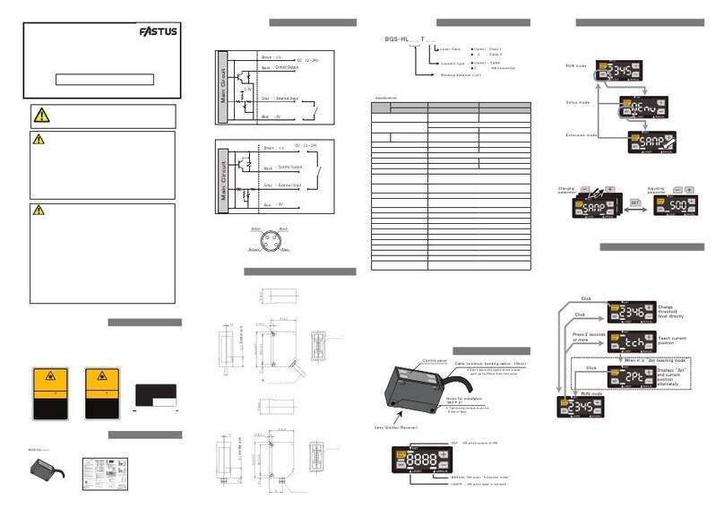
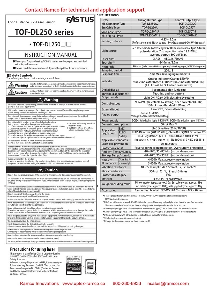
Fastus CD22 Series User manual

Instruction manual
Included items
Before using this product, confirm that the following items are contained in the package.
・&'ƑƑƑƑƑ ・This instruction manual
●The light source of this product applies the visible light semiconductor laser. Do not allow
beam enters an eye, it may cause blindness.
●
mable , explosive gas or liquid environment.
●Do not disassemble or modify the product since it is not designed to automatically stop
the laser emission when open. Disassembling or modifying at customer's end it may
●
herein may result in hazardous radiation exposure.
●It is dangerous to wire or attach/remove the connector while the power is on. Make sure
to turn off the power before operation.
●Installing in the following places may result in malfunction:
1. A dusty or steamy place
2. A place generating corrosive gas
3. A place directly receiving scattering water or oil.
4. A place suffered from heavy vibration or impact.
●The product is not designed for outdoor use.
●Do not use the sensor in a transient state at power on (Approx. 15min. Warm up period)
●Do not wire with the high voltage cable or the power lines. Failure to do this will cause
malfunction by induction or damage.
●Do not use the product in water.
●Operate within the rated range.
●Wipe off dirt on the emitting/receiving parts to maintain correct detection. Also, avoid
direct impact on the product.
Warning Mandatory Requirements
Warning Safety Precautions
Indicates a possible hazard that may result in death, serious
injury, WARNINGS or serious property damage if the product is
used without observing the stated instructions.
CD22 Series
&'ƑƑ &'0ƑƑ
&'ƑƑ &'0ƑƑ
&'ƑƑ &'0ƑƑ
-ThankyouforpurchasingCD22series.Wehopeyouaresatisfiedwithitsperformance.
-Pleasereadthismanualcarefullyandkeepitforfuturereference.
Displacement sensor
Dimensions
ws.
Ŷ
( sensor side )
%URZQ
*UD\
%ODFN
%OXH
:KLWH
Functions of components
㻯㼛㼚㼠㼞㼛㼘㻌㼜㼍㼚㼑㼘
㻴㼛㼘㼑㼟㻌㼒㼛㼞㻌㼕㼚㼟㼠㼍㼘㼘㼍㼠㼕㼛㼚
㻔㻹㻟㻌㻖㻌㻞㻕
㻸㼑㼚㼟㻌㻔㻱㼙㼕㼠㼠㼑㼞㻛㻾㼑㼏㼑㼕㼢㼑㼞㻕
㻖 㼀㼕㼓㼔㼠㼑㼚㼕㼚㼓㻌㼠㼛㼞㼝㼡㼑㻌㼙㼡㼟㼠㻌㼎㼑
㻜㻚㻡㻺䞉㼙㻌㻹㼍㼤㻚
㻯㼍㼎㼘㼑㻌㻔㼙㼕㼚㼕㼙㼡㼙㻌㼎㼑㼚㼐㼕㼚㼓㻌㼞㼍㼐㼕㼡㼟㻌㻦㻌㻝㻜㼙㼙㻕
㻖 㻰㼛㼚㻓㼠㻌㼎㼑㼚㼐㻌㼠㼔㼑㻌㼏㼍㼎㼘㼑㻌㼛㼒㻌㼠㼔㼑㻌㼛㼡㼠㼘㼑㼠
㼜㼍 㼞㼠㻌㼡㼜㻌㼠㼛㻌㻟㻜㼙㼙㻌㼒㼞 㼛㼙㻌㼠 㼔㼑㻌㼏㼍㼟 㼑㻚
●Control panel
㻻㼁㼀㻌㻌㻦㻌㻻㻺㻌㼣㼔㼑㼚㻌㼛㼡㼠㼜㼡㼠㻌㼕㼟㻌㻻㻺
㼆㻱㻾㻻㻌㻦㻌㻻㻺㻌㼣㼔㼑㼚㻌㼦㼑㼞㼛㻌㼞㼑㼟㼑㼠
㻹㻭㻺㼁㻭㻸㻌㻦㻌㻻㻺㻌㼣㼔㼑㼚㻌㻎㻿㼑㼠㼡㼜㻌㼙㼛㼐㼑㻎
㻌㻌㻌㼛㼞㻌㻎㻱㼤㼠㼑㼚㼟㼕㼛㼚㻌㼙㼛㼐㼑㻎
㻸㻭㻿㻱㻾㻌㻌㻦㻌㻻㻺㻌㼣㼔㼑㼚㻌㼘㼍㼟㼑㼞㻌㼕㼟㻌㼑㼙㼕㼠㼠㼑㼐
・Screws
M3 x 15 2 pieces
lebalresaL・
・
M12 type ・ 0W\SH
%ODFN
%URZQ
:KLWH
%OXH
Precautions for using laser
●Regulations in the USA
When exporting laser devices to the USA, the USA laser control,FDA
(Food and Drug Administration) is applied. This product has been already
UHSRUWHGWR&'5+&HQWHUIRU'HYLFHVDQG5DGLRORJLFDO+HDOWK)RU
details, contact our customer service.
・LaserWARNINGlabel
・FDACertificationlabel
Laser diode
:DYHOHQJWKQP0D[RXWSXWPW,//9 degree type.
Color Description
Brown '&9±
Blue 9
Gray (N.C.)
Black 56$
White
PinNo.
1
3
5
4
256%
Use of controls or adjustments or performance of procedures other than those specified
cause personal injury, fire or electric shock.
the laser beam to enter an eye, either directly or refected from refrective object. If the laser
7KLVSURGXFWLVQRWDQH[SORVLRQSURRIFRQVWUXFWLRQ'RQRWXVHWKHSURGXFWXQGHUIODP
ŶM12 type
Ŷ 0W\SH
㻰㼕㼟㼜㼘㼍㼥
㻹㻝㻞㻌㻡㼜㼕㼚㻌㼏㼛㼚㼚㼑㼏㼠㼛㼞
㻰㼕㼟㼜㼘㼍㼥
㻹㻤㻌㻠㼜㼕㼚㻌㼏㼛㼚㼚㼑㼏㼠㼛㼞
㻱㼙㼕㼠㼠㼑㼞㻌㼍㼤㼕㼟
[mm]
㻝㻚㻝
㻝㻞㻚㻡
㻝㻣㻚㻤 㼼㻜㻚㻞
㻟
㻟㻝㼼㻜㻚㻞
㻞㻙㻹㻟
㻠㻠㻚㻠 㼼㻜㻚㻞
㻟㻤㻚㻞 㼼㻜㻚㻞㻟㻚㻝
㻟㻜㻜㼼㻝㻡
䃥㻠㻚㻡
㻠㻡
䃥㻝㻠
㻱㼙㼕㼠㼠㼑㼞㻌㼍㼤㼕㼟
㻝㻚㻝
㻝㻞㻚㻡
㻝㻣㻚㻤 㼼㻜㻚㻞
㻣㻚㻝
㻟
㻟㻝㼼㻜㻚㻞
㻞㻙㻹㻟
㻠㻠㻚㻠 㼼㻜㻚㻞
㻟㻤㻚㻞 㼼㻜㻚㻞㻟㻚㻝
㻝㻢
●
Don't bend the cable when the temperature of the cable or atmosphere is below freezing.
For amazing technical/application support contact Ramco today!
Ramco Innovations
(
800
)
280-6933 www.optex-ramco.com nsales
@
ramcoi.comn

Setup
Part
number
Aluminum housing &'ƑƑ &'ƑƑ &'ƑƑ
SUS housing
&'0ƑƑ &'0ƑƑ &'0ƑƑ
Center of measurement range 15mm 35mm PP
Measurement range ±5mm ±15mm PP
Light source Red laser Diode (wave length 655nm)
0D[RXWSXW:
Max. output: 1mW ※3
Laser
class
IEC/JIS
Spot size ※1P P P
Linearity RIF.S. RIF.S . RIF. S .
Repeatability ※2P P P
Sampling period VVVV AUTO
Temperature drift (typical value)
℃of F.S. ℃of F.S.
℃of F.S.
Indicator Laser indicator: Green / Zero reset indicator: Red
Output indicator: Orange / Mode indicator: Red
Communication I/F 56+DOI'XSOH[0XOWLGURS,)LVQRWVXSSRUWHG
Power supply 9'&
Current consumption PA max.
Protection circuit Reverse connection protection, Over current protection
Protection category ,3LQFOXGLQJFRQQHFWLRQSDUW
Operating THPS+XPLG ~℃a5+ZLWKRXWIUHDVLQJRUFRQGHQVDWLRQ
Storage THPS+XPLG a℃/ 35 ~5+
Ambient illuminance ,QFDQGHVFHQWODPSO[PD[
9ibration resistance a+]'RXEOHDPSOLWXGHPP;Y,Z for 2 hours
Shock resistance PPV2DSSUR[*;Y,Z 3 times each
Material
Case: Aluminum/SUS316L, Front lens: PPSU, Display: PET
Weight Aluminum case with M12 connector : $SSUR[JLQFOXGLQJ
PPFDEOHZLWKFRQQHFWRU
SUS case with M12 connector type : $SSUR[JLQFOXGLQJ
PPFDEOHZLWKFRQQHFWRU
$OXPLQXPFDVHZLWK0FRQQHFWRU $SSUR[J
686FDVHZLWK0FRQQHFWRU $SSUR[J
℃, Sup
ply voltage: 9'& Sampling period: V Averaging: 64, Measuring distance: Center of the range, Testing
object: White ceramic
※2
※2 512 averaging time
※/DVHU&ODVVW\SH0RGHO&'0&'&
●
●Part number legend
㻯㻌㻰㻌㻞㻌㻞㻌
䠻㻙㻌䠻㻌䠻㻌䠻㻌䠻㻌䠻㻌䠻㻌䠻㻌䠻㻌䠻
Measurement center distance (mm)
Output
Laser Class
Connector ƔM12 : M12
ƔC : Mconnector
Ɣ9: 9oltage 9
ƔA : Current 4mA
Ɣ : RS5
ƔNul : Class 1
Ɣ2 : Class 2
&DVH ƔNul : Aluminum
ƔM : SUS316L
●Changingmode
Whileit's"Teachmode","Setupmode"or"Extensionmode",youcanchangethemode
to"Measurementmode"bypressing"ZERO/RUN"button.
Whileit's"Setupmode"or"Extensionmode",theLED"MANUAL"islit.
●Changing parameters
YRXFDQFKRRVHDQGDGMXVWWKHSDUDPHWHUVE\SUHVVLQJDQGEXWWRQV
The mode will be changed to "Measurement mode" by pressing "ZERO/RUN" button.
㻿㻱㼀
䠉䠇䠉 䠇
㻯㼔㼍㼚㼓㼕㼚㼓
㼜㼍㼞㼍㼙㼑㼠㼑㼞
㻭㼐㼖㼡㼟㼠㼕㼚㼓
㼜㼍㼞㼍㼙㼑㼠㼑㼞
㻹㼑㼍㼟㼡㼞㼑㼙㼑㼚㼠
㻌㻌㻌㻌㻌㻌㻌㼙㼛㼐㼑
㼀㼑㼍㼏㼔㼕㼚㼓㻌㼙㼛㼐㼑
㻿㼑㼠㼡㼜㻌㼙㼛㼐㼑
㻱㼤㼠㼑㼚㼟㼕㼛㼚㻌㼙㼛㼐㼑
㻼㼞㼑㼟㼟㻌㼍㼠㻌㼍㻌㼠㼕㼙㼑
㼒㼛㼞㻌㻞㻌㼟㼑㼏㼛㼚㼐
Teach mode
mEnu
modE
FG52
nEAr
FAr
1pt
fG52
2pt
㻿㻱㼀
㻿㻱㼀
1 point Teaching
FGS2
2 point Teaching
tch
㻿㻱㼀
tch
㻿㻱㼀
tch
7HDFKLQJFXUUHQWSRVLWLRQ
7HDFKLQJFXUUHQWSRVLWLRQ
7HDFKLQJFXUUHQWSRVLWLRQ
㻿㻱㼀
To Setup mode
ٹ
Setup mode
ٹ
Teaching mode
ٹ
FGS2 threshold
CALn
㻿㻱㼀
tch
7HDFKLQJFXUUHQWSRVLWLRQ
ٹ
Calibration(Near end of range)
calf
㻿㻱㼀
tch
7HDFKLQJFXUUHQWSRVLWLRQ
ٹ
Calibration(Far end of the range)
ٹ
1HDUVLGHWKUHVKROG
ٹ
SRLQW7HDFKLQJ)DUVLGHWKUHVKROG
䠇
䞊
䠇
䞊
䠇
䞊
䠇
䞊
䠇
䞊
䠇
䞊
䠇
䞊
䠇䞊
VZLWFKLQJ
Measurement mode
CD22 has 3 measurement mode. The mode is chosen by "Teach mode".
Output can be reversed by setting "Output polarity Acti
Following output shows its ON/OFF status as "Light ON
L on
●1 point Teaching
Teaching is done at a position. When the measurement distance is closer than that position, the output
●2 point Teaching
●Calibration (Far end of the range/ Near end of range)
Teaching is done at 2 positions. While the measurement distance is between those positions, the output
The sensor can be calibrated by “Calibration” mode at both far and near end of the measurement range.
This feature is very useful especially when you can’t mount the sensor head parallel to the object surface.
●FGS2
Teaching is done at a position. When the measurement distance is closer than the distance set by +\V
toL
teresis
FAr
hYSt
㻻㻺
㻻㻲㻲
nEAr
hYSt
FGS2
hYSt
㻹㼑㼍㼟㼡㼞㼑㼙㼑㼚㼠㻌㼞㼍㼚㼓㼑
㻻㻺
㻻㻲㻲
hYSt
toL
FAr
hYSt
㻹㼑㼍㼟㼡㼞㼑㼙㼑㼚㼠㻌㼞㼍㼚㼓㼑
㻻㻺
㻻㻲㻲
Position of the target
PP䠄Near end of the range䠅
PP䠄Far end of 㼠㼔㼑㻌㼞㼍㼚㼓㼑䠅
PP䠄Reference distance䠅
㼙㼑㼍㼟㼡㼞㼑㼙㼑㼚㼠㻌㼞㼑㼟㼡㼘㼠䠖
㻙㻡㻜㻚㻜㻜
㼙㼑㼍㼟㼡㼞㼑㼙㼑㼚㼠㻌㼞㼑㼟㼡㼘㼠䠖
㻡㻜㻚㻜㻜
㼙㼑㼍㼟㼡㼞㼑㼙㼑㼚㼠㻌㼞㼑㼟㼡㼘㼠䠖
㻙㻠㻥㻚㻤㻝
㼙㼑㼍㼟㼡㼞㼑㼙㼑㼚㼠㻌㼞㼑㼟㼡㼘㼠䠖
㻡㻜㻚㻝㻥
cALn
㻿㻱㼀
㻙㻡㻜㻚㻜㻜
cALF
㻿㻱㼀
㻡㻜㻚㻜㻜
([DPSOHRI&DOLEUDWLRQRI&'
●
Just calibrate the sensor by “Calibration” mode at far end and near end of the measurement range.
Then, you will get calibrated result if the sensor head is tilted.
A䠅Calibration condition at the factory B䠅When the sensor is mounted tilted
".
".
will be ON.
will be ON.
"from the position that Teaching is done, the output will be ON. It works as FGS sensor.
Ramco Innovations
(
800
)
280-6933 www.optex-ramco.com nsales
@
ramcoi.comn

Extension mode
([WHQVLRQPRGHLVFKRVHQE\SUHVVLQJDQGEXWWRQVDWDWime for 2 second in teach mode top page.
Parameters in Extension mode must be set correctly otherwise it might not work correctly.
Please use with default setting when changing parameters is notQHHGHGPHDQVGHIDXOWVHWWLQJ
rESt
ٹ11: Reset (Initializing)
YES
no
㻿㻱㼀
diSP on
oFF
ٹ12: Display setting
㻿㻱㼀
Initialize the parameters to default setting
Do nothing
Activate the display while ".ey lock"
Desable the display while ".ey lock"
Setup mode
6HWXSPRGHLVFKRVHQE\SUHVVLQJ³6(7´EXWWRQIURP³0HQX´Peans default value)
ٹ4: FGS2 threshold
ALrN
AUG
SANP
cLNP
hoLD
1
8
ٹ$ODPVHWWLQJ
ٹ$YHUDJLQJQXPEHU
64
ٹ: Sampling period
500
1000
&ODPS؟GLVSOD\n|
+ROG؟.HHSSUHYLRXVYDOXH
2000
4000
Auto
s (2k+z)
s (1k+z)
s (+z)
s (+z)
AUTO (Sensor will optimize automatically)
㻿㻱㼀
㻿㻱㼀
㻿㻱㼀
NodE
1Pt
FGS2
2Pt
㻿㻱㼀
ٹ5: Teaching mode
hdct
0000
ٹ$ODP+ROGDQG&ODPS
㻿㻱㼀
toL
21.03
ٹ6: FGS2 hysteresis
㻿㻱㼀
ٹ1: Buad rate
:KHQ$ODPLVVHWDVPHDVXUHPHQWGDWDZLOOEHDVIROORZVIRU$ODP
ٴ
n+ROGDQG&ODPS|
ؙLVDFWLYH
ٴ
n+ROGDQG&ODPS|
LVQRWDFWLYH
can’t measure
can measure
measurement data
hdct
sampling number
.HHSWKHSUHYLRXV
GDWDIRUWKHSHULRG
DQGFODPSWR
n|DIWHUWKDW
پ
Set the value
FGS2
FAr
nEAr
21.03
Set the value
21.03
ٹ2: Near side threshold
Set the value
21.03
ٹ3: 1 point Teaching Far side threshold
Set the value
㻿㻱㼀
㻿㻱㼀
㻿㻱㼀
Acti
ٹ: Output polarity
L on
D on
㻿㻱㼀
512
Default؟CD2215ٸٸ 1.
CD2235ٸٸ .
CD22ٸٸ .
'HIDXOW؟&'ٸٸؙ
ؙؙؙؙ&'ٸٸؙ
ؙؙؙ&'ٸٸؙ
Default؟CD2215ٸٸؙ.
CD2235ٸٸؙ.
CD22ٸٸؙ.
Default؟CD2215ٸٸؙ1.
CD2235ٸٸؙ.
CD22ٸٸؙ.
hoLD
.HHSWKHSUHYLRXV
GDWDZKLOHLWbV$ODP
VWDWXV
پ
bAud
9.6
19.2
38.4
㻿㻱㼀
9,ESs
19,ESs
,ESs
,ESs
115,ESs
,ESs
312,ESs
,ESs
,ESs
625,ESs
,333bps
,ESs
1,,ESs
57.6
115.2
230.4
312.5
468.8
500.0
625.0
833.3
937.5
1250
SRLQW7HDFKLQJ
)*6
SRLQW7HDFKLQJ
Light ON: ON when exceeds the threshold
Dark ON: ON when less than the threshold
Once
times
64 times
512 times
hYSt
NtoP
thrE
2Ero
SEnS
21.036HWWKHYDOXH
㻿㻱㼀
NAH 0$;؟0D[LPXPGLVWDQFH
㻿㻱㼀
bASE %DVH؟6HWWKUHVKROGWRORZHVWOHYHO
㻿㻱㼀
21.036HWWKHYDOXH
㻿㻱㼀
㻿㻱㼀
Pt5
Pt4
Pt3
Pt2
Pt1
3W؟WKSRLQWIURPVHQVRUVLGH
3W؟WKSRLQWIURPVHQVRUVLGH
3W؟UGSRLQWIURPVHQVRUVLGH
3W؟QGSRLQWIURPVHQVRUVLGH
3W؟&ORVHVWSRLQWIURPVHQVRUVLGH
P400
P200
P100
3؟6HWWKUHVKROGWRXSSHUOHYHO
3؟6HWWKUHVKROGWRPLGGOHOHYHO
3؟6HWWKUHVKROGWRORZHUOHYHO
&KR R VHPHDVXUHPHQW
SRLQWZKHQLWUHFHLYHV
PX OW LSOHUHsHFWLRQIURP
WKHREMHFW
6HWWKUHVKROGOHYHOWR
UHFRJQL]HDV
PHDV X UHPHQWSRLQW
Auto $XWR؟$GMXVWDXWRPDWLFDOO\
N__6
N__1
؟0D[LPXPVHQVLWLYLW\
؟0LQLPXPVHQVLWLYLW\
䡚
6HW6HQVLW LYLW \R I
WKHVHQVRU
ٹ+\VWHUHVLV
ٹ0HDVXUHPHQWSRLQW
ٹ7KUHVKROG
ٹ=HURUHVHWYDOXH
ٹ6HQVLWLYLW\
'HIDXOW&'ٸٸٸ
&'ٸٸٸ
&'ٸٸٸ
6HWGLVSOD\YDOXH
IRU=HURUHVHW
Miscellaneous function
:KLOHLWVPHDVXUHPHQWPRGHSUHVVDWDWLPH
IRUVHFRQG7KHQZLOOEHVKRZQ
:KLOHLVVKRZQDQ\DFFHVVH[FHSW5HOHDVLQJ.H\
ORFNZLOOEHQHJOHFWHG
ٹ.H\ORFNIXQFWLRQ
ٴ$FWLYDWH.H\ORFN
:KLOH.H\ORFNLVDFWLYDWHGLWZLOOEHUHOHDVHGE\SUHVVLQJ
DWDWLPHIRUVHFRQGV7KHQZLOOEHVKRZQ
$IWHUWKLVSURFHVVHYHU\DFFHVVZLOOEHDFFHSWHG
ٴ5HOHDVH.H\ORFN
䠉䠇
䠉䠇
Loc
uLoc
Loc
:KLOHLWVPHDVXUHPHQWPRGHSUHVVIRUVHFRQGV
7KHQZLOOEHVKRZQ7KHSRVLWLRQRIGHFLPDOSRLQW
YDULHVE\VHQVRUW\SH
:KHQVHWWLQJ=HURUHVHWWKHUHGLQGLFDWRU/('=(52ZLOOEH
21
ٹ=HURUHVHWIXQFWLRQ
ٴ6HW=HURUHVHW
ٴ5HOHDVH]HURUHVHW
㼆㻱㻾㻻㻌
㻾㼁㻺
00.00
:KLOHLWVPHDVXUHPHQWPRGHSUHVVIRUVHFRQGVWR
UHOHDVH=HURUHVHW
㼆㻱㻾㻻㻌
㻾㼁㻺
:KHQLWbVVHWn|
can’t measure
can measure
measurement data
䠉
䠇
䠉
䠇
䠉
䠇
䠉
䠇
䠉
䠇
䠉
䠇
䠉
䠇
䠉
䠇
䠉
䠇
䠉
䠇
䠉
䠇
䠉
䠇
䠉
䠇
䠇
䞊
䠇
䞊
䠇
䞊
䠇
䞊
䠇
䞊
Ramco Innovations
(
800
)
280-6933 www.optex-ramco.com nsales
@
ramcoi.comn

any obligations on the part of manufacture.
)RUPRUHLQIRUPDWLRQTXHVWLRQVDQGFRPPHQWVUHJDUGLQJ
6SHFLILFDWLRQVDQGHTXLSPHQWDUHVXEMHFWWRFKDQJHZLWKRXW
products, please contact us below.
Attention: Not to be Used for Personnel Protection.
Never use these products as sensing devices for personnel protection. Doing so could
lead to serious injury or death. These sensors do not include the VHOIFKHFNLQJ redundant
circuitry necessary to allow their use in personnel safety applications. A sensor failure or
PDOIXQFWLRQFDQFDXVHHLWKHUDQHQHUJL]HGRUGHHQHUJL]HGVHQVR routputcondition.
Please consult our distributors about safety products which meet 26+A, ANSI and IEC
standards for personnel protection.
Communication
Communication method 56+DOI'XSOH[0XOWLGURS,)LVQRWVXSSRUWHG
Transmission code Binary
Data length ELW
Stop length 1bit
Parity check Nil
Baud rate (bps)
NNNN1NNNNNNNN0
67;(7;
Ŷ'DWD)RUPDW
Transmission data : 67; COMMAND DATA1 DATA2 (7; BCC
Incoming data : 67; $&. RESPONSE1 RESPONSE2 (7; BCC
Incoming data (error) : 67; 1$. ERROR CODE + (7; BCC
67; +(7; + $&. +1$. +%&& ;25RIYDOXHVKDWFKHG
Basic commands : &+ Individual function commands
:+ Writing the setting
5+ Reading out setting
Error code table : + Address is invalid
+ BCC value is invalid
+ Invalid command is issued except "C", "W", "R"
+
+ Setting value is invalid (out of range)
Ŷ&+SDUDPHWHUWDEOH
Command Type DATA1
(upper)
DATA2
(lower)
Description
Reading out
Measurement value
Write %K K
Read Upper data Lower data Response in 2 bytes ※1
Reading out Output
status
Write %K K
Read K Output
status
ELW 21
ELW WKHVWDWXVKDVEHHQUHDG
Writing the setting Write $K K Write the setting into EEPROM.
PVEHUHTXLUHGXQWLOWKHODVHUSRZHUVWDEOH
Read K K
Teaching FGS2 Write 11h K
Read K K
Teaching near side
point
Write 11h K
Read K K
Teaching far side
point
Write 11h K
Read K K
Laser ON Write $K K
Read K K
Laser OFF Write $K K
Read K K
Execute Zero reset Write A1h K
Read K K
Release Zero reset Write A1h K
Read K K
([HFXWH.H\ORFN Write A1h K
Read K K
5HOHDVH.H\ORFN Write A1h K
Read K K
Initializing
Write K K Initialize all parameters except communication
speed and UHERRt. The communication won't
worrk while initializing.
Read K K
0HDVXUHPHQWDQGVHWWLQJYDOXHDUHGHDFULEHGDVVLJQHGKH[DGHFLPDO
Model &'ƑƑ &'ƑƑ &'ƑƑ
Range ±5mm ±15mm PP
Unit P P P
Data
+H[ (&K K FA24h '&K (&K K
Data
(Decimal)
ŶWriting Data
Writing is done as following proceedure.
1. Read out setting
Execute Command "R" (Reading out setting) on the target parameter.
Set "Address" at "DATA1" and "DATA2".
2. Write setting
Execute Command "W" (Writing the setting) on the target parameter.
Writing data is done to the address set at "1. Read setting".
Example: Setting "Sampling period" to "AUTO"
1. Read out "Sampling period"
Transmission command : 67;K R (52h) K K (7;K BCC (14h)
Incoming data : 67;K $&.K K K (7;K BCC K)
2. Write the setting
Transmission command : 67;K :K K K (7;K BCC (53h)
Incoming data : 67;K $&.K K K (7;K BCC K)
,QFRPLQJGDWDRIFRPPDQG:WULWLQJWKHVHWWLQJZLOOEHKDQGK
Ŷ6HWWLQJSDUDPHWHUWDEOH
Setting Address/
Parameter
DATA1
(upper)
DATA2
(lower)
Description
Model type
Address K K Return center value of measurement
range (only for checking model type)
Parameter
K )K 15mm type
K 23h PPW\SH
K 64h PPW\SH
Measurement mode
Address K K
Parameter
K K 2 point Teaching
K K 1 point Teaching
K K FGS2 Teaching
Near side threshold Address 41h K
Parameter Upper data Lower data
Far side threshold Address 41h K
Parameter Upper data Lower data
FGS2 threshold Address 41h K
Parameter Upper data Lower data
FGS2 hysteresis Address 41h K
Parameter Upper data Lower data
Output polarity
Address K K
Parameter
K K Light ON: ON when exceeds the threshold
K K Dark ON: ON when less than the
threshold
Sampling period
Address K K
Parameter
K K V
K K V
K K V
K K V
K K AUTO
Averaging number
Address K $K
Parameter
K K Once
K K WLPHV
K K 64 times
K K 512 times
Alarm setting
Address K &K
Parameter K K Clamp
K K +ROG
$ODUP+ROGDQG
Clamp
Address 41h K
Parameter Upper data Lower data
Display setting
Address K (K
Parameter K K ON
K K OFF
+\VWHUHVLV Address 41h K
Parameter Upper data Lower data
Measurement point
Address K K
Parameter
K K 0$;0D[LPXPGLVWDQFH
K K
K K
K K
K K
K K
Threshold
Address K 12h
Parameter
K K Base : Lowest level
K K /HYHOORZHUOHYHO
K K /HYHOPLGGOHOHYHO
K K /HYHOXSSHUOHYHO
Zero reset value Address 41h 12h
Parameter Upper data Lower data
Sensitivity
Address K 14h
Parameter
K K AUTO
K K 1 : Minimum sensitivity
K K 2
K K 3
K K 4
K K 5
K K 6 : Maximum sensitivity
([HFXWHWKHFRPPDQG55HDGRXWEHIRUHH[HFXWLQJFRPPDQGW" (Write).
Pt1 : Closest point from sensor side
Pt5 : 5th point from sensor side
Pt4 : 4th point from sensor side
Pt3 : 3rd point from sensor side
Pt2 : 2nd point from sensor side
Manufactured and sold by :
䊻
KWWSZZZRSWH[IDFRPURKVBFQ
Ramco Innovations
(
800
)
280-6933 www.optex-ramco.com nsales
@
ramcoi.comn
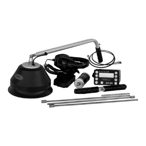
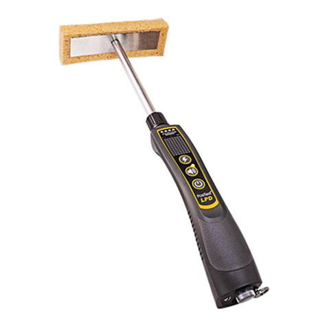
Other Fastus Security Sensor manuals
Popular Security Sensor manuals by other brands

ETC
ETC Echo Dual Tech installation guide
Honeywell
Honeywell Series 3000 MkII Technical manual
AQUALEAK
AQUALEAK WG2 Installation and operation instruction manual
SICK
SICK C 4000 operating instructions

suprema
suprema Secure Tamper How to configure
Zimmer
Zimmer MFS02-S-KHC-IL Installation and operating instructions
