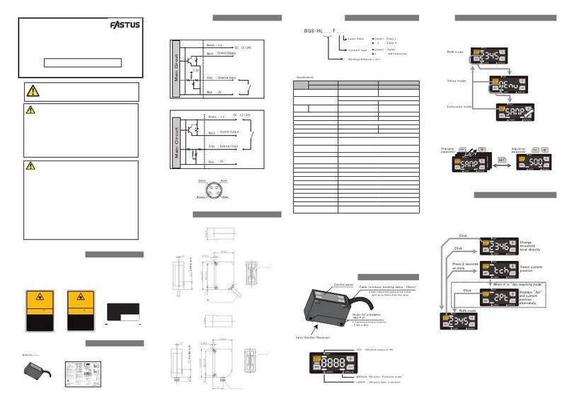
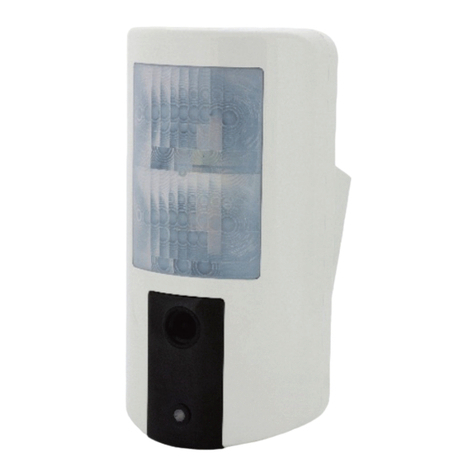
Fastus TOF-DL250 Series User manual

TOF-DL250 series
・TOF-DL250□□
LongDistanceBGSLaserSensor
●ThankyouforpurchasingTOF-DLseries.Wehopeyouaresatisfied
withitsperformance.
●Pleasereadthismanualcarefullyandkeepitforfuturereference.
Indicator
Digitaldisplay
Thresholdadjustment
Outputmode
Controloutput
Analogoutput
Powersupply
Currentconsumption
Externalinput
Hysteresis
TOF-DL250AC
AnalogOutputType
M8ConnectorType
TOF-DL250A
2mCableType
TOF-DL250A-5
5mCableType
TOF-DL250AM12
M12Pig-tailType
Sensingdistance
Lightsource
Laserclass
Samplingperiod
Responsetime
Spotsize*2
TOF-DL250T
TOF-DL250T-5
TOF-DL250DC
ControlOutputType
TOF-DL250TM12
0.25~2.5m
(
Reflectance
:6%Black
paper
/18%Gray
paper
/90%White
paper
)
15%Max.(
Reflectance
:6%Blackpaper/18%Graypaper/90%Whitepaper)
Redlaserdiode(
wavelength
:650nm,
maximumoutput
:64mW,
pulseduration:7ns,repetitionrate:11.11MHz)
averageoutput:390μWMax.
Φ10mm/2.5m
CLASS1(IEC/JIS/FDA*1)
DC12~30Vincludingripple(P-P)10%*
5
DC10~30Vincludingripple(P-P)10%
60mAMax.*6
200μS
0.5msMax.(averagingnumber:1)
Teachingand+/-buttons
LaserOFF,Externalteaching
Upto2units
Reverseconnectionprotection,Overcurrentprotection
-10~50℃/35~85%RH(nocondensation)
Ambient
illuminance
-40~70℃/35~95%RH(nocondensation)
IP67
Sunlight
4,000lxMax.atreceivingwindow
3,000lxMax.atreceivingwindow
Incandescentlight
7segment3digit(unit:cm)
EMCDirective(2014/30/EU)
Applicable
regulations
Applicablestandards
RoHSDirective(2011/65/EU),ChinaRoHS(MIITOrderNo.32)
EMC
RoHS
Safety
FDARegulations(21CFR1040.10and1040.11*7)
EN60947-5-7/IEC60825-1
M8connectortype:approx.30g,2mcabletype:approx.88g,
5mcabletype:approx.188g,M12pig-tailtype:approx.48g
1mountingbracket:BEF-WK190,2screws:M3x20mm
Current
:4~20mA/
Voltage
:
0~10V
(selectablebysetting)
EN60947-5-2/IEC60825-1
Type
Outputindicator(OrangeLED*3)/
Stableindicator(GreenLED)/Unstableindicator(RedLED)
(AllLEDwillbeOFFwhenLaserisOFF)
LightON/DarkONselectablebysetting
NPN/PNP(selectablebysetting)opencollectorDC30V,
100mAmax.(Residual1.8Vmax)*4
Crosstalkprevention
Protectioncircuit
AmbientTemp./Humid.
StorageTemp./Humid.
Vibrationresistance
Shockresistance
Protectioncategory
10~55Hzamplitude1.5mmX,Y,Zeach2h
500m/s2X,Y,Zeach3times
Material
Weightincludingcable
Case:PC/Lens:PMMA
Accessories
WhenexportingthisproducttoUSA,it'snecessaryto
followlaserregulationofUSAFDA.Thisproducthas
beenalreadyreportedtoCDRH(CenterforDevices
andRadio-logicalHealth).Fordetails,contactour
customerservice.
Precautionsforusinglaser
ThisproductisclassifiedasClass1LaserProductby
JISC6802:2014/IEC60825-1:2007and2014Laser
SafetyStandard.
*1TheseproductsareClassifiedasCLASS1byIEC60825-1:2007accordingtoLaserNoticeNo.50,
FDAGuidanceDocument.
*2Definedwithcenterstrength1/e2(13.5%)atthecenter.Theremaybeleaklightotherthanthespecifiedspotsize.
Thesensormaybeaffectedwhenthereisahighlyreflectiveobjectclosetothedetectionarea.
*3Analogoutputtypehave2litatsametime.M8connectortype(TOF-DL250DC)has2for2controloutputs.
*4Analogoutputtypehave1.M8connectortype(TOF-DL250DC)has2.Othertypeshave3controloutputs.
*5UsepowersupplywithDC12.0VMin.togetsufficientoutputforanalogoutput.
*6Excludingloadcurrentforcontroloutput.
*7ExceptfordeviationspursuanttolasernoticeNo.50.
INSTRUCTIONMANUAL
SPECIFICATIONS
Warning
!
!
Donotdisassemble,repair,modify,deformunderpressure,orattempttoincineratethisproduct.
Doingsomaycauseinjuryorfire.
Thisproductisnotexplosion-proofandshouldnotbeusedaroundflammableorexplosivegasesor
liquids.Doingsomaycauseignitionresultinginafire.
Donotuseairdustersoranyspraythatusesflammablegasaroundtheproductorontheinsideof
theproduct.Doingsomaycauseignitionresultinginafire.
Donotinstallthisproductinanyofthefollowinglocations.
Doingsomaycauseafire,damage,oramalfunction.
1.Locationswheredust,salt,ironpowders,orvapor(steam)ispresent.
2.Locationssubjectedtocorrosivegasesorflammablegases.
3.Locationswherewater,oil,orchemicalsplashesmayoccur.
4.Locationswhereheavyvibrationsorimpactsmayoccur.
5.Locationswheretheambienttemperatureexceedstheratedrange.
6.Locationssubjecttorapidtemperaturechanges(orwherecondensationoccurs).
Caution
Warning
Intheeventofamalfunctionsuchassmokecomesoutfromtheproduct
Ifyoudetectanymalfunctionincludingemissionofsmoke,abnormalsmellsorsounds,orthehousing
becomingveryhot,immediatelystopoperatingtheproductandturnoffthepowertothecontroller.
Doingsomaycauseafire.Repairingtheproductisdangerousandshouldinnowaybeperformedby
thecustomer.ContacttheOptexFAsalesoffice.
Incasewaterenterstheproduct
Ifwateroranyotherliquidenterstheproduct,immediatelystopoperatingtheproductandturnoff
thepowertothecontroller.Usingtheproductinthisconditionmaycauseafire.
Donotdroptheproductorsubjecttheproducttostrongimpacts.Doingsomaydamagetheproduct.
Caution
Followtheinstructionsinthismanualorthespecifiedinstructionmanualwhenwiringtheproductforthecorrect
wiringmethod.Incorrectwiringcandamagetheproductorcauseamalfunction.Outputcannotbeconnectedwith
otherLEDcontrollerinseriesnorinparallel.
Donotexcessivelytwistorapplystresstothecable.
Doingsomaydamagethecableortheconnector.
Whenconnectingthecable,makesuretoholditbytheconnectorportion,anddonotapplyexcessiveforcetothecable.
Whendisconnectingtheconnector,becarefulnottotouchtheterminalsinsidetheconnector,anddonot
allowforeignobjectstoentertheconnector.
Routewiringseparatelyfromhigh-voltagecircuitsandpowercircuits.
Ifthewiresareroutedtogether,inductionmayoccur,whichcancauseamalfunctionordamagetheproduct.
Ifthisisunavoidable,useaconductiveobjectsuchasaproperlygroundedconduitasashield.
Installthisproductasfarawayfromhigh-voltageequipment,powerequipment,equipmentthatgenerates
largeswitchingsurges,welders,invertermotors,oranyequipmentthatcanbeasourceofnoise.
Usetheproductwithintheratedranges.
Installthisproductandthededicatedcontrollersecurely.
Failuretoensuresecureinstallationcanresultintheproductsfallingandbecomingdamaged.
Makesuretoturnthepoweroffbeforeconnectingordisconnectingthecable.
Connectingordisconnectingwhileenergizedmaydamagetheproduct.
Donotusethisproductinanon-industrialenvironment.
Doingsomaycauseinductionorradiationinterference.
Indicatesthatanyimproperoperationorhandlingmayresultinmoderateorminorinjury,
andinrarecases,seriousinjuryordeath.Alsoindicatesariskofseriouspropertydamage.
Indicatesthatanyimproperoperationorhandlingmayresultinminorinjuryor
propertydamage.
7.Locationswithstrongelectricor
magneticfields.
8.Outdoorlocationsorlocations
subjecttodirectsunlight.
■SafetySymbols
Thesafetysymbolsandtheirmeaningsareasfollows.
Thelightsourceofthisproductappliesthevisiblelightsemiconductorlaser.Donotallowthelaserbeamtoenteran
eye,eitherdirectlyorreflectedfromreflectiveobject.Ifthelaserbeamentersaneye,itmaycausedamageorproblems
oftheeye.
Donʼtbendthecablewhenthetemperatureofthecableoratmosphereisbelowfreezing.
Donʼtusethesensorontransientstateafterpoweron(approx.300ms).
Thesensorperformanceordigitaldisplayvaluesmaydependontheindividualunitsortheconditionofdetectingobject.
آ
آ
ContactRamcofortechnicalandapplicationsupport

■PNPmode
DC12〜30V
Controloutput
Externalinput
Analogoutput
Whenusedasoutput
Whenusedasinput
0V
■NPNmode
Load
DC12~30V
Control
output
Externalinput
Analogoutput
0V
Whenusedasoutput
Maincircuit
Whenusedasinput
Maincircuit
■NPNmode
Whenusedasoutput
DC10~30V
Control
output1
Control
output2
Control
output3
Whenusedasinput
0V
■PNPmode
DC10~30V
Whenusedasinput
Control
output1
Control
output2
Control
output3
Whenusedasoutput
0V
M8connectorpin-out
M12pig-tailpin-out
4
2
13
①・・・DC12~30V
②・・・Analogoutput
③・・・0V
④・・・Externalinput
(switchabletocontroloutput)
①・・・DC12~30V
②・・・Analogoutput
③・・・0V
④・・・Controloutput
⑤・・・Externalinput
1
24
3
5
Black・・・Controloutput
White・・・Analogoutput
Gray・・・Externalinput
Cablewirecolor
Brown・・・DC12~30V
Blue・・・0V
■Controloutputtype
M8connectorpin-out
M12pig-tailpin-out
4
2
13
①・・・DC10~30V
②・・・Controloutput1
③・・・0V
④・・・Externalinput
(switchabletocontroloutput2)
①・・・DC10~30V
②・・・Controloutput2
③・・・0V
④・・・Controloutput1
⑤・・・Externalinput
(switchabletocontroloutput3)
1
24
3
5
Black・・・Controloutput1
White・・・Controloutput2
Gray・・・Externalinput
(switchabletocontroloutput3)
Cablewirecolor
Brown・・・DC10~30V
Blue・・・0V
Circuitdiagram
■Analogoutputtype
Maincircuit
Load Load Load
Load
LoadLoad Load
Maincircuit
Ramco Innovations www.optex-ramco.co 800-280-6933 nsales
@
ramcoi.com

Nameofthepartsandsetup
Nameandfunctionofbuttonsandindicatorsvarydependsonthemodel.
TOF-DL250A
TOF-DL250AC
TOF-DL250AM12
TOF-DL250A-5
TOF-DL250T
TOF-DL250TM12
TOF-DL250T-5
TOF-DL250DC
Stableindicator(stable:green/
unstable:red),OFFwhenlaser
isOFF
Display
Outputindicator3(orange)
Stableindicator(stable:green/
unstable:red),OFFwhenlaser
isOFF
Outputindicator(orange)
+Q1
Q1
Q1
SET
RUN
−
+Q2
Q1
Q1
RUN
−
Q1
Q2
SET Q3
Q3
+Q2
Q1
Q1
Q2
SET
RUN
−
Display
Display
Outputindicator2(orange)
Outputindicator1(orange)
Outputindicator2(orange)
Outputindicator1(orange)
(2indicatorslitatsametime)
Stableindicator(stable:green/
unstable:red),OFFwhenlaser
isOFF
Button Functionwhilesensing Functionwhilesetting
+
−/Q1
RUN
SET
Q2(*)
Q3(*)
Bypressing1secondormore,TeachingofOutput1
willbedoneforcurrentdistance.Then,thedisplay
shows“tc1”andthethresholdlevel.
*ForTOF-DL250AC,externalinputtobeset“out”.
Bypressing1secondormore,TeachingofOutput2
willbedoneforcurrentdistance.Then,thedisplay
shows“tc2”andthethresholdlevel.
*ForTOF-DL250DC,externalinputtobeset“out”.
Bypressing1secondormore,TeachingofOutput3
willbedoneforcurrentdistance.Then,thedisplay
shows“tc3”andthethresholdlevel.
*Externalinputtobeset“out”.
Increasesettingvalue
Decreasesettingvalue
Backto“RUN”(sensing)
mode
Fixthesettingvalue
Gotosettingmode
Bypressing1secondormore,Keyswillbelockedand
thedisplayshows“Loc”.
Whilekeysarelocked,bypressing1secondormore,
key-lockwillbereleasedandthedisplayshows“uLc”.
Gotosettingmode
*Validonlyforthemodelthathas“Q2”and“Q3”shownonthepanel.
Installation
Horizontal
tovertical Verticalto
horizontal
M8connectorcanberotatefrom
horizontalpositiontoverticalor
verticalpositiontohorizontalas
pictureabove.Donʼtrotateexceeding
stopper.Doingsowillcausebreakage.
Tighteningtorque:0.5N・mMax.
Dimensions
[mm]
■Cabletype,M12pig-tailtype
■M8connectortype
●Withoutmountingbracket
M84pinconnector
㻞㻤㻚㻞㻡
㻠㻚㻤
3.1
2.6 39.2
1.2
7
6
2.8
1.9
32.8
44.4
9
16
2-Φ3.1
Φ4.55core2m/5mcable
Φ4.5M125pin300mmpig-tailcable
17.4
Receiver
Emitter
■M8connectortype
㻞㻚㻤㻟㻝㻚㻟
㻝㻞㻚㻢㻡
㻹㻤㻌㻠㼜㼕㼚㻌㼏㼛㼚㼚㼑㼏㼠㼛㼞
●Withmountingbracket
2-M3
9
7.85
10.45 39.2
31.3 2.8
4.1
1.29
1.5
53.8
23.85
15
17.4
20
19.4
9.3
11.7
31.3
2-R 2.1
2-R 2.1
R22.1
20 °
Receiver
Emitter
Φ4.55core2m/5mcable
Φ4.5M125pin300mmpig-tailcable
■Cabletype,M12pig-tailtype

●Specificationsaresubjecttochangewithoutnotice
●Formoreinformation,questionsandcommentsregardingproducts,
pleasecontactusbelow.
Notusedelayfunction(*)
OFFdelay:Delaysoutputtiming
ofONtoOFF
■9.Delay
Setdelayfunctionforoutputondetection
ONdelay:Delaysoutputtiming
ofOFFtoON
Oneshot:OutputONforthe
periodset
Inputvalue
■10.Nearsidesetting
Setthedistancetooutput4mA(currentoutput)/0V(voltageoutput)
Range:0~400,Default:0,Unit:cm
Range:0~400,Default:300,Unit:cm
Range:0~400,Default:300,Unit:cm
Range:0~400,Default:300,Unit:cm
■11.Farsidesetting
■12.Output1thresholdlevel
■13.Output2thresholdlevel
■14.Output3thresholdlevel
■15.Offset
+
−
+
−
Inputvalue
Setthedistancetooutput20mA(currentoutput)/10V(voltageoutput)
+
−
Inputvalue
SetthethresholdlevelofOutput1
+
−
Inputvalue
SetthethresholdlevelofOutput2
+
−
Inputvalue
SetthethresholdlevelofOutput3
+
−
Inputvalue
SettheoffsetvaluetoaddontheTeachinglevel
(Offsetvalueisvalidfrom2ndtimeofTeaching)
+
−
Inputvalue
Range:0~999
Default:0
Unit:10ms
*OnlyforAnalogoutputtype
*OnlyforAnalogoutputtype
*Onlyforcontroloutputtype
*Onlyforcontroloutputtype
*Onlyforcontroloutputtype
Range:0~400,Default:300,Unit:cm
Range:-50~+50,Default:0,Unit:cm
ON:Activatethedisplay(unit:cm)(*)
OFF:Darkenthedisplaywhenthereisnobuttonoperation
over30seconds
■8.Display
SelectON/OFFofthedisplay
+
−
Byclicking“RUN”buttonorleavethesettingmodefor30seconds,itwillgobackto
“RUN”(sensing)mode.
Setinput/outputasNPN(*)
Setinput/outputasPNP
■2.NPN/PNPselection
Wonʼtbechangedbyinitializing
LightON:TurnsONwhenthedistanceexceedsthreshold(*)
DarkON:TurnsONwhenthedistanceislessthanthreshold
■4.OperatingmodeLightON/DarkON(stabilityoutput)selection
1time
4times
■5.Averaging
Setnumberofaveraging
16times
64times(
*)
256times
OutputMaximumcurrent/voltage(*)
Hold:Keepthevaluejustbeforethealarm
■6.BehaviorwhenAlarm
SetbehaviorofAnalogoutputwhenitʼsoutofsensing
Notinitialize
Executeinitialize
■7.Initializing
InitializesettingstothevaluesetwhenshippedexceptNPN/PNPsetting
Setascurrentoutput4~20mA(*)
Setasvoltageoutput0~10V
■3.AnalogoutputCurrent/Voltageselection
+
−
+
−
+
−
+
−
+
−
+
−
*OnlyforAnalogoutputtype
*OnlyforAnalogoutputtype
Stability-LightON:Output1turnsONwhenstable
(Otheroutput:LightON)
Stability-DarkON:Output1turnsONwhenunstable
(Otheroutput:DarkON)
Extensionmode
■1.Externalinput(MFinput)
Setfunctionofexternalinput
Disableexternalinput(neglecttheinput)
Useasoutput(asfollowingtable)
Analogoutputtype:TeachingOutput1
Controloutputtype:
Lessthan1second:TeachingOutput1
Morethan1secondlessthan2seconds:TeachingOutput2
Morethan2seconds:Invalid
LaserOFF:Killthelaserpower(*)
LaserON:Activatethelaserpower
+
−
Targetoutput
Output1
Output3
Output2
Model
TOF-DL250DC
TOF-DL250T
TOF-DL250T-5
TOF-DL250TM12
TOF-DL250A
TOF-DL250A-5
TOF-DL250AC
TOF-DL250AM12
Not
applicable
Press“SET”togettosettingmenu
●SupportfortheChinaRoHSdirective
Youcangetto“Extensionmode”byclicking“RUN”buttonor“SET”button.
(“*”meansdefaultvalue)
OPTEX FA CO., LTD.
91Chudoji-Awata-choShimogyo-kuKyoto600-8815JAPAN
This manual suits for next models
8
Other Fastus Security Sensor manuals
Popular Security Sensor manuals by other brands

SMART
SMART TL-2100CP Change Pad Indicator Installation and use instructions
System Sensor
System Sensor SpectrAlert MP120K Installation and maintenance instructions
Schaller Automation
Schaller Automation VN115/87plus EX Operation manual
ESYLUX
ESYLUX MD-W200i Installation and operating instructions
Jaycar Electronics
Jaycar Electronics LA-5044 Installation and operating instructions
FUHR
FUHR NB649N Installation and operation instructions
