Faudi SLUGGUARD User manual

FAUDI Aviation GmbH Phone: +49 (6428) 44652-57 Manual
Scharnhorststraße 7B Fax: +49 (6428) 44652-223 SLUGGUARD®
3526 Stadtallendorf Email: sensor@faudi-aviation.com Revision 6
Germany www.faudi-aviation.com Language: EN
Manual
SLUGGUARD®
Series FFM/FFMI
Bulk Water Sensor according EI 1592 for use in aviation fuelling applications

Manual
SLUGGUARD®
Manual SLUGGUARD® Revision 6
1
1. Revisions 2
2. Introduction 3
3. Intended Use 3
4. Safety Instructions 3
4.1 Operational safety 3
5. Installation, Commissioning and Operation 4
5.1 Return 4
5.2 Contact 4
6. Identification 5
6.1 Reception 5
6.2 Scope of Delivery 6
7. Possible Applications 7
7.1 Bulk Water Sensor according EI 1592 in Pipe Section 7
7.2 SLUGGUARD® in Water Sump of Filter Water Separator 7
7.3 SLUGGUARD® Below Water Sump on Filter Vessels 8
7.4 Options and their Accessories 8
7.5 Ball Valve for SLUGGUARD® 9
8. General Safety and User Instructions 1
8.1 Safety 1
8.2 Installation for Various Applications 1
8.3 Connection 11
8.4 Electrical Connection in Explosion Hazard Areas 11
8.5 Explosive Gas Atmospheres Zone and Zone 1 12
8.6 Isolating Barrier for SLUGGUARD® 13
8.7 Relay Outputs of Barrier 13
9. Cleaning, Maintenance and Repair 14
9.1 Disposal 14
1 . Technical Data 15
11. ATEX Approval 16
12. EU Declaration of Conformity 18

Manual
SLUGGUARD®
Manual SLUGGUARD® Revision 6
2
1. Revisions
Revision Revision Details Received and
Entered by Date
Standard Manual Matthias Aden 23/ 7/2 19
3 ATEX Certificate on Page 16 Matthias Aden 15/ 1/2 2
5 EU Declaration of Conformity on Page 18 Stefan Graf 14/ 8/2 2
6 General Adjustment Stefan Graf 13/ 7/2 21
Notes on Safety Icons and Symbols
Warning!
This symbol alerts you to hazards. They can cause serious damage to the
instrument or to persons if ignored.
Caution!
This symbol alerts you to possible faults which could arise from incorrect
operation. They could cause damage to the instrument if ignored.
Note!
This symbol indicates important items of information.

Manual
SLUGGUARD®
Manual SLUGGUARD® Revision 6
3
2. Introduction
For secure and error-free operation of the device, these operating instructions must be read with care before
commissioning and kept at a site well accessible for the operator/s.
Should further questions arise after the lecture of these operating instructions please do not hesitate to contact our
sales representatives.
3. Intended Use
The SLUGGUARD
®
bulk water sensor is designed for the detection of bulk quantity of free water in running aviation
fuel or for the distinction of media (fuel / water) in low points of filter water separators or in drain points of filter
vessels. The manufacturer is not liable for damages caused by improper or non-intended use of the device.
4. Safety Instructions
This manual provides operation and routine maintenance instructions for the FAUDI Aviation SLUGGUARD
®
.
Read this manual and ensure that you fully understand its content before you attempt to install, use or maintain
the SLUGGUARD
®
.
Work on electrical equipment is to be conducted by trained specialists only, according to valid regulations.
Attention must be paid to the requirements of VDE 1 when setting up high-power electrical units with nominal
voltages of up to 1 V, including associated standards and stipulations.
Check the details on the type plate to ensure that the equipment is connected to the correct
mains voltage.
Protect against touching dangerously high electrical voltages. Opening the equipment is strictly prohibited.
The equipment is only to be used within the permitted temperature and operation ranges (see Chapter 1 ).
All CHANGEs of the SLUGGUARD
®
with parts which are not specified or approved by FAUDI Aviation GmbH, as well as
repair and service with unspecified parts will result in loss of the CE conformity and guarantee.
In case of doubt, please turn directly to FAUDI Aviation GmbH, respectively to your FAUDI Aviation Distributor or
Service organization.
Danger, safety, prohibition and risk notes in this manual must be complied with under all
circumstances!
4.1 Operational Safety
The SLUGGUARD® is designed and tested according to the state of the art and left the factory in perfect functioning
order. Relevant regulations and european standards have been met.
As the user, you are responsable for complying with the following safety conditions:
-Installation instructions
-Local prevailing standards and regulations

Manual
SLUGGUARD®
Manual SLUGGUARD® Revision 6
4
5. Installation, Commissioning and Operation
For cabling and mechanical setup of the SLUGGUARD
®
please refer to the training documents (Certified Installer
Training).
Before commissioning of the entire measuring point, check that all connections are installed correctly. Ensure that
electrical cables are not damaged. Do not operate damaged products and secure them against unintentional
commissioning. Mark the damaged product as being defective.
Measuring point faults may only be rectified by authorised and specially trained personnel. If faults cannot be
rectified, the products must be taken out of service and secured against unintentional commissioning.
Repairs may only be carried out by manufacturer or by a designated service organisation.
5.1 Return
If the device requires repair, please send it in cleaned condition to the appropriate sales centre. Please use the
original packaging, if possible.
When sending for repair, please enclose a note with a description of the error and the application.
Please enclose the certificate of decontamination (to be found on the download section of FAUDI-Aviation-Sensor
homepage.
5.2 Contact
Contact address of manufacturer:
FA DI Aviation GmbH
Scharnhorststraße 7B
D-3526 Stadtallendorf
Tel.: +49 (6428) 44 652 57
Fax: +49 (6428) 44 652 223
Email: sensor@faudi-aviation.com
Web: www.faudi-aviation.com

Manual
SLUGGUARD®
Manual SLUGGUARD® Revision 6
5
6. Identification
SLUGGUARD® with LED
6.1 Reception
You should have received a device like above.
Make sure the packaging is undamaged!
Inform the supplier about damage to the packaging.
Keep the damaged packaging until the matter has been settled.
Make sure the contents are undamaged!
Inform the supplier about damage to the delivery contents. Keep the damaged products until the matter has been
settled.
Check that the scope of delivery is complete and agrees with your order and the shipping.
The packaging material used to store or to transport the product must provide protection against shock and
humidity. The original packaging offers the best protection. Also, keep to the approved ambient conditions (see
"Technical data").
If you have any questions, please contact your supplier or your sales centre responsible.

Manual
SLUGGUARD®
Manual SLUGGUARD® Revision 6
6
6.2 Scope of Delivery
The following items are included in the delivery:
One Set comprises:
a) 1 SLUGGUARD®
b) 1 Dedicated barrier for hazardous area installation of SLUGGUARD® in zone / 1
c) 1 Connection cable between sensor and barrier

Manual
SLUGGUARD®
Manual SLUGGUARD® Revision 6
7
7. Possible Applications
7.1 Bulk Water Sensor according EI 1592 in Pipe Section
7.2 SLUGGUARD® in Water Sump of Filter Water Separator

Manual
SLUGGUARD®
Manual SLUGGUARD® Revision 6
8
7.3 SLUGGUARD® Below Water Sump on Filter Vessels
7.4 Options and their Accessories
SLUGGUARD® Stainless Steel without LED, G1/2 process
connection, M12 plug connector, PNP output
Part No. 6 4
SLUGGUARD® Stainless Steel with LED, G1/2 process connection,
M12 plug connector, PNP output
Part No. 6 1
Barrier with power supply and relays output
Part No
. 6 41
Connection cable with M12 connector, 15 m length Part No. 5261 2
Measuring ball valve for SLUGGUARD
®
Part No. 6 511

Manual
SLUGGUARD®
Manual SLUGGUARD® Revision 6
9
7.5 Ball Valve for SLUGGUARD®
Pos Description Description 2 Material
1 Double nipple (not in scope of delivery) R 1″ / ¾″ 1.4571
2 SLUGGUARD® Without LED -
3 O-Ring 17,86x2,62 NBR
4 Ball Valve SLUGGUARD® SS
When using the ball valve for the SLUGGUARD
®
– the sealing will be generated via O-ring.
No need to use Teflon tape!
Tightening torque: 2 – 3 Nm max.
Rp1"
DETAIL
Sensor with O-ring

Manual
SLUGGUARD®
Manual SLUGGUARD® Revision 6
1
8. General Safety and User Instructions
8.1 Safety
Intended use
The sensor must be used solely for the level detection of liquids in applications which are specified and approved
by FAUDI Aviation GmbH.
The sensor must only be used for media against which the housing material and sensor tip are resistant.
Staff qualification
Installation and operating personnel must be qualified and instructed
. This applies in particular to assembly,
installation and explosion protection. Make sure that the staff has read and understood these instructions.
Technical condition
Use the sensor only when in perfect technical condition. Only use FAUDI Aviation GmbH accessories.
FAUDI Aviation GmbH will accept no liability for other manufacturers’ accessories.
Risk of burns from hot media
During operation the sensor housing may warm up to over 5 °C. When working with hot media provide protection
against burns.
Explosion hazard areas
Ensure that safety requirements are complied with. Do not use equipment that would be exposed to hard impacts.
8.2 Installation for Various Applications
When using the SLUGGUARD
®
without the dedicated ball valve – use sufficient sealant material like PTFE (Teflon
tape) to seal the sensor.

Manual
SLUGGUARD®
Manual SLUGGUARD® Revision 6
11
SLUGGUARD® with common G1/2 process connection:
Ensure that vessel and pipelines are free of media.
Seal thread on sensor with Teflon tape (PTFE).
Screw in SLUGGUARD
. Tightening torque G 1/2: 3 Nm max.
8.3 Connection
A voltage supply of 12 V to 3 V DC should be provided
1) Switch off supply voltage.
2) Connect the sensor in accordance with the pin assignment.
Terminal assignment
Output
type
E
quivalent circuit
Fun
c
tion
M12
-
A
4-pin
C
abl
e
outlet
PNP + Vs 1 Brown
SW1 (NO) 4 Black
SW
1 (NC)
2
White
GND ( V) 3 Blue
8.4 Electrical Connection in Explosion Hazard Areas
Depending on the variant, the SLUGGUARD
®
is approved for most explosion hazard areas.
CA TION!
Risk of fatal accident due to a wrongly connected sensor
In explosive gas atmospheres of zone or 1, use FAUDI Aviation GmbH isolation barriers.
Use in minimum insulated cable conforming to IP67 specification.
Allow only persons trained in explosion protection to perform the installation.

Manual
SLUGGUARD®
Manual SLUGGUARD® Revision 6
12
8.5 Explosive Gas Atmospheres Zone and Zone 1
The SLUGGUARD
®
can be used in explosion hazard areas of zone or zone 1.
Sensors with PNP can only use FAUDI Aviation GmbH isolation barriers which are easy to install.
Approval for SL GG ARD® with certificate number: TÜV 19 ATEX 247467 X (see Chapter 11)
ATEX II 1 G Ex ia IIC T4/T5
Highest values for selection of barriers Ui: 3 V DC
Li: 1 mA
Pi: ,75 W
Internal capacitance: Ci: 43 nF
1)
Internal inductance: Li: 1 µH
2)
Temperature class
Standard version T4: -4 < Tamb < 85 °C
T5: -4 < Tamb < 74 °C
SLUGGUARD® uses a 4-wire cable. IN PNP connection – only black, brown and blue cables are in use – white is only
needed for programming.

Manual
SLUGGUARD®
Manual SLUGGUARD® Revision 6
13
8.6 Isolating Barrier for SLUGGUARD®
8.7 Relay Outputs of Barrier
SLUGGUARD and barrier are configured to use relay connectors 1 (COM) and 3 (NO).
If you connect as shown in the above scheme this –a missing SLUGGUARD® or a broken cable will create an ALARM to
indicate fail safe error.
For the connection of relay output 1 and 3 – internal switch inside the barrier must be set to normal.
Open front cover
Check switch to sit as shown above:

Manual
SLUGGUARD®
Manual SLUGGUARD® Revision 6
14
9. Cleaning, Maintenance and Repair
Cleaning
Cleaning of the SLUGGUARD® is recommended – preferable during quarterly check.
Maintenance
Regular maintenance is not required.
Repair
Do not repair the SLUGGUARD
®
yourself.
Send the damaged sensor to FAUDI Aviation GmbH.
9.1 Disposal
Do not dispose of in household waste.
Separate materials and dispose of in compliance with nationally applicable regulations
.

Manual
SLUGGUARD®
Manual SLUGGUARD® Revision 6
15
1 . Technical Data
Environmental conditions
Operating temperature range -4 …+85 °C
Storage temperature range
-
4 …+85 °C
Ambient humidity < 98 % RH,
condensing
Protection class IP67
IP69K (with appropriate cable)
Oscillations (sinusoidal)
(EN 6 68-2-6)
1.6 mm p-p (2…25 Hz),
4 g (25…1 Hz), 1 oktave / min.
Power supply
Voltage supply range 12…3 V DC
Reverse polarity protection
y
es
Current consumption
(without load)
25 mA typ.,
5 mA max.
Power-up time < 2 s
Features
Repeatability
± 1 mm
Hysteresis ± 1 mm
Response time .1 s
Damping . …1 . s (configurable)
Output signal
Output type
PNP
NPN
Current load 2 mA max.
Short circuit protection Yes
Voltage drop PNP: (+Vs -1.5V) ± .5 V,
Rload = 1 kΩ
NPN: (+1.5 V) ± .5 V,
Rload = 1 kΩ
Leakage current max. ± 1 µA
Switching logic Normally open (NO),
active low
Normally closed (NC),
high enabled

Manual
SLUGGUARD®
Manual SLUGGUARD® Revision 6
16
11. ATEX Approval

Manual
SLUGGUARD®
Manual SLUGGUARD® Revision 6
17

Manual
SLUGGUARD®
Manual SLUGGUARD® Revision 6
18
12. EU Declaration of Conformity
Other manuals for SLUGGUARD
1
Table of contents
Other Faudi Control System manuals
Popular Control System manuals by other brands
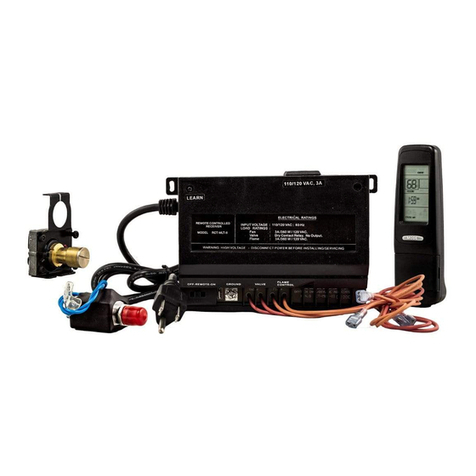
Skytech
Skytech RCTS-MLT-IV Installation and operation instructions
Signature Control Systems
Signature Control Systems EZ Indoor 8124US Installation and programming guide
C.P. Electronics
C.P. Electronics Rapid EBR-4SC user guide

Show Tec
Show Tec SC-2412 manual
Spraying Systems
Spraying Systems TeeJet Technologies 744E user manual

TrolMaster
TrolMaster Tent-X instructions
