Faulhaber 3242 BX4 Series User manual

EN
Brushless DC Servomotors
Series
3242…BX4
3268…BX4
Instruction Manual
WE CREATE MOTION


3
Version:
3rd edition, 10.03.2011
Copyright
by Dr. Fritz Faulhaber GmbH & Co. KG
Daimlerstr. 23/25 · 71101 Schönaich
All rights reserved, including those to the translation.
No part of this description may be duplicated, reproduced,
stored in an information system or processed or trans-
ferred in any other form without prior express written
permission of Dr. Fritz Faulhaber GmbH & Co. KG.
This instruction manual has been prepared with care.
Dr. Fritz Faulhaber GmbH & Co. KG cannot accept any li-
ability for any errors in this instruction manual or for the
consequences of such errors. Equally, no liability is ac-
cepted for direct losses or consequential damages resulting
from improper use of the devices.
The pertinent regulations regarding
safety engineering and interference suppression as well as
the specifications in this instruction manual must be com-
plied with when using the equipment.
Subject to change without notice.
The respective current version of this instruction manual is
available on FAULHABER's internet site:
www.faulhaber.com
Imprint

4
1 Important Information 6
1.1 Symbols used in this instruction manual 6
1.2 Safety instructions 7
1.3 Documentation 7
1.4 Ambient conditions 8
1.5 Servicing/ maintenance 9
1.6 Troubleshooting 9
2 Description 10
2.1 General product description 10
2.1.1 Motor without attachment 10
2.1.2 Motor with encoder IE3 or IE3 L 11
2.1.3 Motor with AES absolute encoder 12
2.1.4 Motor with SC speed controller 13
2.1.5 Motor with SCDC Speed Controller 14
3 Installation 15
3.1 Assembly 15
3.2 EMC compatible installation 16
3.2.1 Description of the EMC measures 16
3.3 Connector pin assignment 17
3.3.1 Motor without attachment 17
3.3.2 Motor with encoder IE3 or IE3 L 18
3.3.3 Motor with AES absolute encoder 19
3.3.4 Motor with SC speed controller 20
3.3.5 Motor with SCDC Speed Controller 21
3.4 Connection examples 22
3.4.1 Motor without attachment 22
3.4.2 Motor with encoder IE3 22
3.4.3 Motor with encoder IE3 L 23
3.4.4 Motor with AES absolute encoder 24
3.4.5 Motor with SC speed controller 25
3.4.6 Motor with SCDC Speed Controller 26
4 Functional Description 27
4.1 Motor without attachment 27
4.1.1 Connection functions with digital Hall sensors (standard version) 27
4.1.2 Connection functions with analog Hall sensors (special number 3692) 29
4.2 Motor with encoder IE3 or IE3 L 31
4.2.1 Connection functions 31
4.3 Motor with AES absolute encoder 35
4.3.1 Connection functions 35
4.4 Motor with SC speed controller 37
4.4.1 Connection functions 37
4.4.2 Configuration 39
4.4.3 Special configurations 41
4.4.4 Parameter settings 43
4.4.5 Technical information 45
Table of Contents

6
1 Important Information
This instruction manual describes the handling and technical features of FAULHABER’s series
32xx…BX4 brushless DC servomotors.
Series 32xx...BX4 drives can be optionally combined with integrated encoders, encoders with line
drivers, absolute encoders or speed controllers to form complete drive units.
Please read through the complete instruction manual before using the motor.
Keep this instruction manual in a safe place for later use.
The information given in this instruction manual refers to the standard version of the motors. Please
refer to any additional information sheet provided in the event of differences in information due to
a customer-specific motor modification.
1.1 Symbols used in this instruction manual
WARNING! Warning!
This pictogram with the wording "Warning!" indicates an imminent danger which can result in
physical injuries.
fThis arrow points out the appropriate action to take to prevent the imminent danger.
CAUTION! Caution!
This pictogram with the wording "Caution!" indicates an imminent danger which can result in slight
physical injuries or material damage.
fThis arrow points out the appropriate precautions.
REGULATION! Regulations, guidelines and directives
This pictogram with the wording "Regulation" indicates a statutory regulation, guideline or directive
which must be observed in the respective context of the text.
NOTE Note
This "Note" pictogram provides tips and recommendations for use and handling of the component.

7
1 Important Information
1.2 Safety instructions
Observance of the following safety instructions is prerequisite for trouble-free and safe operation of
the motor. Therefore, please carefully read through all the notes and follow them when using the
motor.
Intended use
The servomotor is designed as a drive for small mechanisms, as well as for continuously running and
positioning applications, e.g. pump and scanner drives or in metering technology.
External control electronics are required to operate the motors without integrated speed
controllers.
The motor contains magnetic, electromagnetic and electronic components. Any effects as well as
the specific relevant national regulations must be taken into account when using the motor.
The motor may not be used in environments where contact with water, chemicals and/or dust is
possible or in potentially explosive atmospheres!
The forces, torques and accelerations acting on the motor are limited.
Please ask the manufacturer for information about individual use under special ambient
conditions.
1.3 Documentation
The following table gives an overview of the documentation of the FAULHABER electronic products
described in this instruction manual:
Products Data sheets Instruction manuals
Series
3242…BX4
3242…BX4
mit Encoder
3242…BX4 SC
3242…BX4 SCDC
3268…BX4
3268…BX4
mit Encoder
3268…BX4 SC
3268…BX4 SCDC
BX4 32 mm
(MA05021)
3242…BX4 X X
3242…BX4 IE3 X X
3242…BX4 IE3 L X X
3242…BX4 AES X X
3242…BX4 SC X X
3242…BX4 SCDC X X
3268…BX4 X X
3268…BX4 IE3 X X
3268…BX4 IE3 L X X
3268…BX4 AES X X
3268…BX4 SC X X
3268…BX4 SCDC X X
The documentation is available on request or from the FAULHABER internet site
(www.faulhaber.com).
8
1 Important Information
1.4 Ambient conditions
CAUTION! Shock loads
The noise emitted is increased and the life of the ball bearings and therefore of the servomotor be-
comes limited if they are exposed to impacts.
fThe servomotor can still function if it is not exposed to higher shock loads than defined according
to EN 60068-2-27.
fThe servomotor may not be exposed to higher vibration stresses than defined according to
EN 60068-2-6.
CAUTION! Risk of damage
If the servomotor is installed on the mounting flange, the mounting flange can be damaged by high
radial loads or stresses on the servomotor or by screws tightened with excessive torque.
fDo not load the servomotor at the rear end with a radial force greater than 60 N.
fTighten the screws with maximum 128 Ncm. Note the strength of the screws!
NOTE Service life
The full life is reached if the servomotor is not exposed to shock or vibration loads.
CAUTION! Risk of damage
The ribbon cables may be damaged if the static or dynamic load is too high.
The following applies to cables with contact spacing 1.27 AWG28:
fThe tension exerted on the cable must not exceed 30 N in each direction. If the cable is exposed to
constant tensile loads the limit is 17 N.
fIf the radii are small the cable may not be bent several times as otherwise the Litz wires will break.
The bending radii if laid once must be larger than 1.2 mm.
The following applies to cables with contact spacing 2.54 AWG24:
fThe tension exerted on the cable must not exceed 60 N in each direction. The limit for constant
tensile loads is 20 N.
fIf the radii are small the cable may not be bent several times as otherwise the Litz wires will break.
The bending radii if laid once must be larger than 1.8 mm.
The following applies to all cables:
fIn case of frequent bending, the recommended minimum bending radius is 10 mm. The possible
number of bending cycles increases with increasing bending radius.
fThe cable may not be bent at temperatures < -10 °C.

9
1 Important Information
1.5 Servicing / maintenance
The servomotor is designed to be maintenance free. No maintenance measures are necessary.
1.6 Troubleshooting
The servomotor is designed to be fault-free, provided the parameters given in this instruction manu-
al are complied with. Should a malfunction occur in spite of this please contact the manufacturer.
Switchboard: +49(0)7031/638-0
E-Mail: info@faulhaber.de
Internet: www.faulhaber.com

10
2 Description
2.1 General product description
Product information
32 … G … BX4 …
IE3:
IE3 L:
AES:
SC:
SCDC:
Encoder IE3 attachment
Encoder IE3 with line driver attachment
Absolute encoder attachment
Speed Controller attachment
Speed Controller attachment, two-wire version
BX4: BX4 motor family
012:
024:
Supply voltage of the motor 12 V
Supply voltage of the motor 24 V
G: Shaft diameter 5 mm
42:
68:
Motor length 42 mm
Motor length 68 mm
32: Motor diameter 32 mm
2.1.1 Motor without attachment
The servomotor is an electronically commuted (brushless) DC motor. Compared to mechanically com-
muted electric motors, its main outstanding feature is a much longer life.
The motor is based on the self-supporting coil technology, FAULHABER system, and essentially con-
sists of a three-phase winding (stator) and a four-pole permanent magnet (rotor). The commutation
takes place via an additional external control.
The rotor position is detected by 3 Hall signals.
FAULHABER’s SC2804 or SC5008 control is recommended for operation of the servomotor.
1
2
5
4
6
78
910 11 12
3
1 Cover
2 Adapter board
3 Ribbon cable
4 Rear motor bearing
5 Spring
6 Winding with Hall sensors
7 Housing
8 Steel yoke
9 Rotor with permanent magnet
10 Shaft
11 Front motor bearing
12 Mounting flange

11
2 Description
2.1 General product description
2.1.2 Motor with encoder IE3 or IE3 L
In this option, the servomotor described in Chapter 2.1.1 has an encoder with 3 output channels
(IE3). A permanent magnet on the shaft generates a moving magnetic field which is measured and
further processed by means of a rotary encoder. At the encoder's outputs there are two rectangular
signals, phase-shifted by 90°, with up to 1024 pulses and one index pulse per motor.
The encoder is available with different pulse rates (32, 64, 128, 256, 512 or 1024 pulses/revolution).
The pulse rate is included in the motor designation. Further resolutions from 1 – 127 pulses are avail-
able on request.
Example
Motor: 3242 … BX4 IE3-128 L
Features: Motor 3242 … BX4 with encoder, 128 pulses/revolution, line driver
Line driver
Encoders with an "L" in the encoder designation have differential encoder signal outputs in accord-
ance with TIA 422. Therefore, common-mode interferences are suppressed and longer supply connec-
tors are enabled. These three differential signals must be joined together again on the connection
side with a receiver module. The precise function is described in Chapter 4.2 “Motor with encoder IE3
or IE3 L”.
1
2
5
4
3
678
10
9
11
12 13
14 15 16 17
1 Cover
2 Built-on housing
3 Ribbon cable 1
4 Ribbon cable 2
5 Encoder board
6 Sensor magnet
7 Magnet holder
8 Mounting flange
9 Rear motor bearing
10 Spring
11 Winding with Hall sensors
12 Housing
13 Steel yoke
14 Rotor with permanent magnet
15 Shaft
16 Front motor bearing
17 Mounting flange

12
2 Description
2.1 General product description
2.1.3 Motor with AES absolute encoder
In this option, the servomotor described in Chapter 2.1.1 has an absolute encoder with serial
interface.
A permanent magnet on the shaft generates a moving magnetic field which is measured and further
processed by means of a single chip rotary encoder.
Absolute angle information with a resolution of 4096 steps is available at the outputs, which can be
queried via a serial interface (SSI). Absolute means that each shaft position within a revolution is as-
signed a unique angle value. This is available immediately after switching on.
The absolute encoder is optimally suited to commutation, speed and position control. It can also be
used for sinus commutation. The advantage in this case is that the motor is run more efficiently and
torque ripple is minimised.
It is connected via only one ribbon cable (unlike the version with incremental encoder).
Example
Motor: 3242 … BX4 AES-4096
Features: Motor 3242 … BX4 with absolute encoder, resolution 4096 steps/revolution
1
2
4
3
567
9
8
10
11 12
13 14 15 16
1 Cover
2 Built-on housing
3 Ribbon cable
4 Encoder board
5 Sensor magnet
6 Magnet holder
7 Mounting flange
8 Rear motor bearing
9 Spring
10 Winding with Hall sensors
11 Housing
12 Steel yoke
13 Rotor with permanent magnet
14 Shaft
15 Front motor bearing
16 Mounting flange

13
2 Description
2.1 General product description
2.1.4 Motor with SC speed controller
In this option, the servomotor described in Chapter 2.1.1 has integrated commutation electronics (SC
speed controller), which provides diverse motor control possibilities.
The motor offers the following functions:
Control of the speed through set value input or control of the speed through the motor voltage.
Switchover of direction of rotation via switch input.
Reading out the speed signal via the frequency output.
CAUTION! Risk of damage
Switching over the motor's direction of rotation (reversing duty) too quickly can cause damage.
fDo not use the speed controller for reversing duty.
123
456
8
7
11
910
12 13 14 15
1 Cover
2 Heat transfer pad
3 Built-on housing
4 Ribbon cable
5 Controller board
6 Mounting flange
7 Rear motor bearing
8 Spring
9 Housing
10 Steel yoke
11 Winding with Hall sensors
12 Rotor with permanent magnet
13 Shaft
14 Front motor bearing
15 Mounting flange

14
2 Description
2.1 General product description
2.1.5 Motor with SCDC Speed Controller
In this option, the servomotor described in Chapter 2.1.1 has integrated two-wire commutation
electronics (Speed Controller SCDC). The drive can be operated just like a common DC motor with
brushes.
The motor offers the following functions:
Motor speed proportional to the applied supply voltage.
Rotational direction switched over by reversing the connection cables.
Integrated current limiting.
Optionally on request: Speed limiting, fixed speed control.
CAUTION! Risk of damage
Switching over the motor's direction of rotation (reversing duty) too quickly can cause damage.
fDo not use the speed controller for reversing duty.
2
1
34
567
8
9
12
10 11
13 14 15 16
1 Small cover plates
2 Cover
3 Heat transfer pad
4 Built-on housing
5 Ribbon cable
6 Controller board
7 Mounting flange
8 Rear motor bearing
9 Spring
10 Housing
11 Steel yoke
12 Winding with Hall sensors
13 Rotor with permanent magnet
14 Shaft
15 Front motor bearing
16 Mounting flange

15
3 Installation
3.1 Assembly
The servomotor must be installed according to certain specifications to prevent malfunctions and
damage.
CAUTION! Material damage
Incorrect installation or installation with the wrong fixing materials can cause irreparable damage to
the motor's function and/or damage the motor.
fObserve the following assembly instructions.
Use environment
Depending on its use, the servomotor can get very hot. Appropriate heat dissipation possibilities
must be provided.
Shaft load
When pressing parts on the motor shaft it must be held against on the opposite side. Otherwise the
maximum allowable load values (axial at a standstill) must be noted and observed.
Mounting flange
When fixing the servomotor to the front flange, the screws must be locked as they can loosen at
high temperatures. The maximum length of the fixing screws must be noted and observed as
otherwise the motor will be destroyed.
The depth of engagement in the motor may not be exceeded.
Right
The motor is fixed by the screws on the
mounting flange.
Wrong
The motor is securely clamped to the attach-
ment with a U-bolt.
Electrical connection
It is necessary to ensure that the ribbon cable is laid without risk of damage during installation and
operation, e.g. through chafing, squeezing or too small bending radii. The maximum load of the
cable must be noted and observed.
More detailed information on installation of the products described in these instructions is given in
the relevant data sheets on the FAULHABER internet site (www.faulhaber.com).
16
3 Installation
3.2 EMC compatible installation
CAUTION! Length of the connection leads
The maximum length of the connection leads is limited.
fAll connection leads may not exceed a length of 3 m.
Optimisation of performance with respect to emission and immunity requires the additional EMC
measures:
Ensuring the necessary immunity in industrial uses can require use of an EMC suppressor circuit.
Motor designation Use environment Interference type Action
Motor without attachment Industrial environment
Motor with SC speed controller Industrial environment Emission EMC suppressor circuit
This table shows which additional EMC measures can be implemented to optimise the behaviour of
the equipment in the intended environment with regard to immunity.
The units are intended for industrial use only. If the devices are used in the home, in business or in
commerce or in a small business, appropriate measures must be taken to ensure that the emitted
interference is below the permitted limits!
3.2.1 Description of the EMC measures
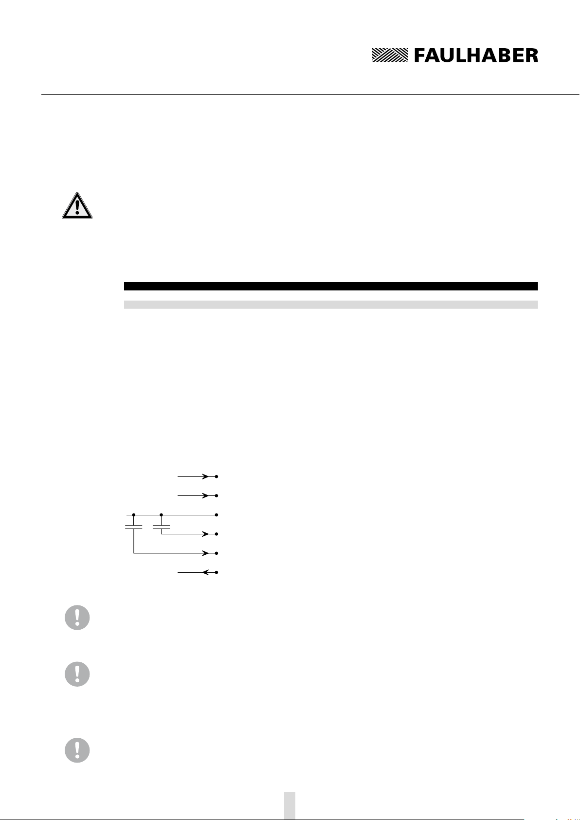
The EMC suppressor circuit (motor with Speed Controller SC only)
Circuit diagram 1
FG
DIR
Unsoll
GND
C2 C1
Umot
UpC1 Ceramic capacitor 220 nF
C2 Ceramic capacitor 220 nF
NOTE Capacitor C1:
If the ceramic capacitor C1 is used, malfunctions can occur in PWMntarget operating mode.
fUse signal source with low internal resistance in PWMntarget operating mode.
NOTE Capacitor C2:
If using the ceramic capacitor C2, a firmware update with the Motion Manager PC firmware may no
longer be possible.
fRemove the C2 capacitor when updating the firmware.
NOTE Motor without attachment:
A control, e.g. Faulhaber's SC5008, is recommended for operation of the servomotor.
17
3 Installation
3.3 Connector pin assignment
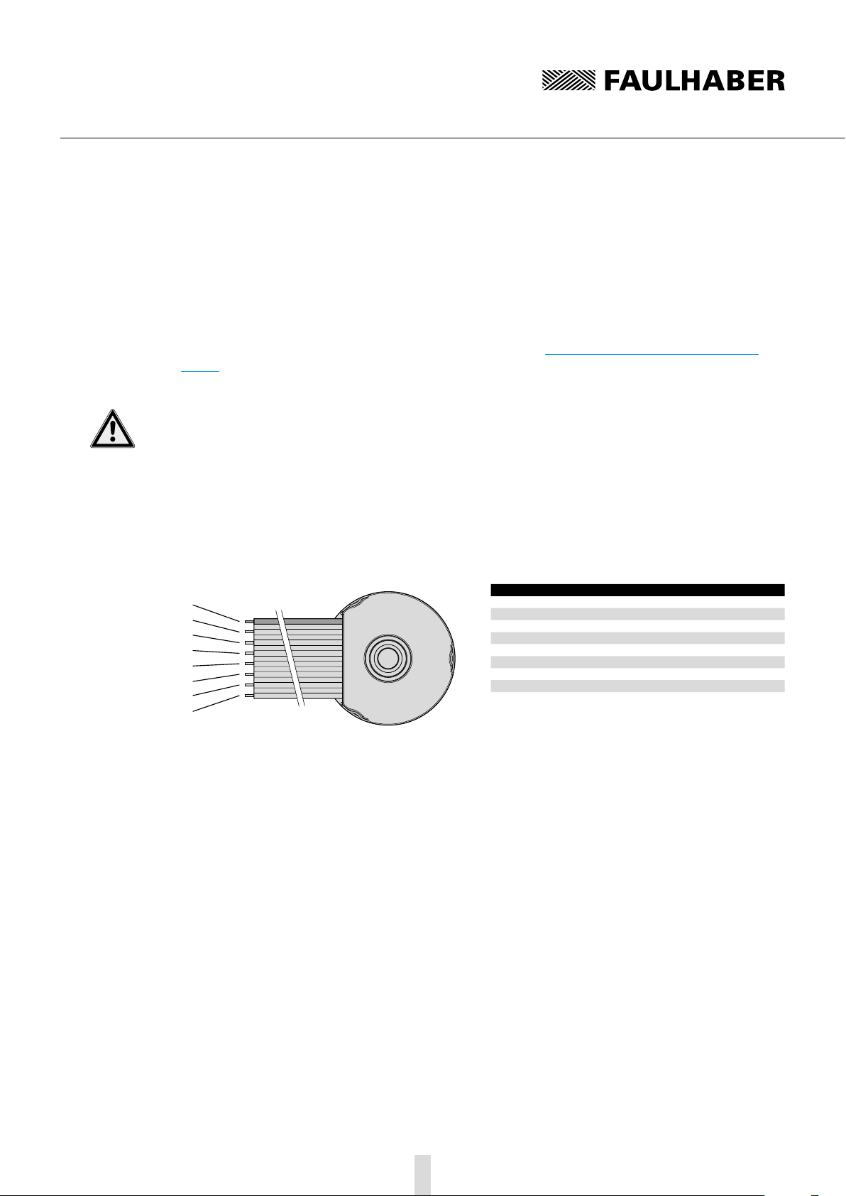
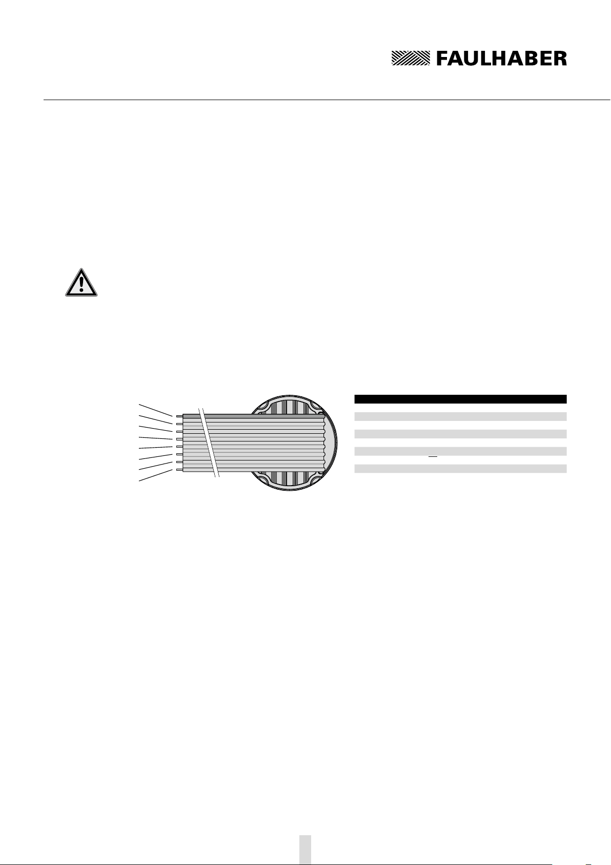
3.3.1 Motor without attachment
The servo motor is equipped, as a standard, with an eight-core ribbon cable for the power supply to
the motor phases and sensor technology as well as for transfer of the digital (standard) or analog
(option 3692) Hall sensor signals.
For more detailed information on the hall sensor signals, see Chapter 4.1 “Motor without attach-
ment”.
CAUTION! Electronic damage / ESD protection
Electrostatic discharges at the connection pin assignment of the ribbon cable can result in irreparable
damage to the motor.
fIt may only be processed in ESD protected workplaces.
Incorrect connection of the cores can cause damage to or destruction of the electronics.
fConnect the ribbon cable in accordance with the connector pin assignment, see table.
Connection pin assignment of the ribbon cable
1
2
3
4
5
6
7
8
Core Function
1 (red) Phase C
2 Phase B
3 Phase A
4 GND
5 UDD
6 Hall sensor C
7 Hall sensor B
8 Hall sensor A

18
3 Installation
3.3 Connector pin assignment
3.3.2 Motor with encoder IE3 or IE3 L
Apart from the eight-core connection cable for supplying the motor described in Chapter 3.3.1, the
servomotor with encoder also has a six-core ribbon cable (ten-core in encoders with line driver) for
the encoder's connections.
CAUTION! Electronic damage / ESD protection
Electrostatic discharges at the connection pin assignment of the ribbon cable can result in irreparable
damage to the motor.
fIt may only be processed in ESD protected workplaces.
Incorrect connection of the cores can cause damage to or destruction of the electronics.
fConnect the ribbon cable in accordance with the connector pin assignment, see table.
Connection pin assignment of the ribbon cable for encoders without line driver (IE3)
1
2
3
4
5
6
Core 1 motor cable
Core Function
1 (red) n.c.
2 Channel I (index)
3 GND Enc
4 UDD Enc
5 Channel B
6 Channel A
Connection pin assignment of the ribbon cable for encoders with line driver (IE3 L)
1
2
3
4
5
6
7
8
9
10
Core 1 motor cable
Core Function
1 (red) n.c.
2 UDD Enc
3 GND Enc
4 n.c.
5Channel A
6 Channel A
7Channel B
8 Channel B
9Channel I (index)
10 Channel I (index)
19
3 Installation
3.3 Connector pin assignment
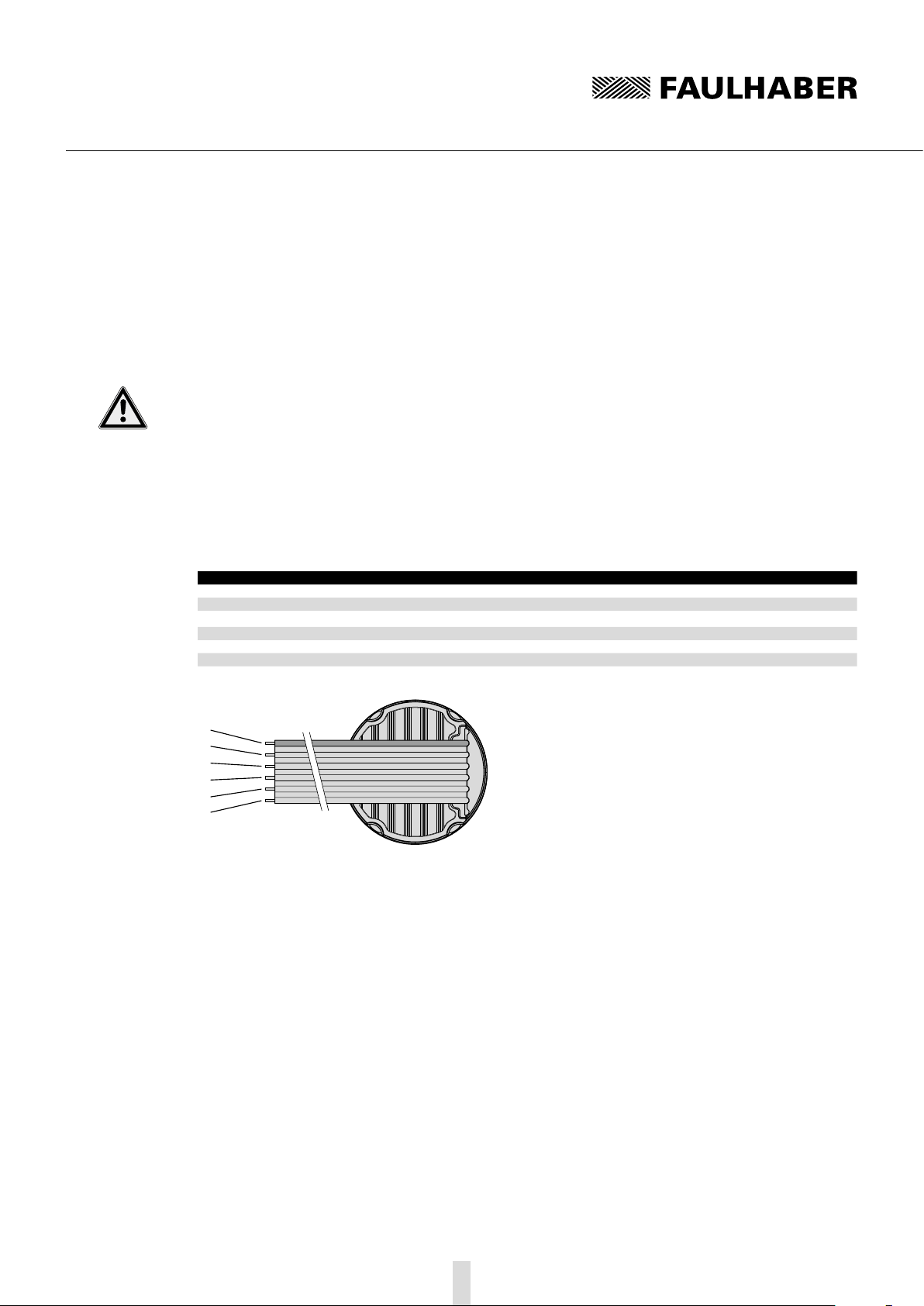
3.3.3 Motor with AES absolute encoder
The servomotor with AES absolute encoder is equipped, as a standard, with an eight-core ribbon
cable for the power supply to the phases and encoder, and for signal transfer of the angle informa-
tion via a serial interface (SSI).
CAUTION! Electronic damage / ESD protection
Electrostatic discharges at the connection pin assignment of the ribbon cable can result in irreparable
damage to the motor.
fIt may only be processed in ESD protected workplaces.
Incorrect connection of the cores can cause damage to or destruction of the electronics.
fConnect the ribbon cable in accordance with the connector pin assignment, see table.
Connection pin assignment of the ribbon cable
1
2
3
4
5
6
7
8
Core Function
1 (red) Phase C
2 Phase B
3 Phase A
4 GND Enc
5 UDD Enc
6 CLK
7Res. (CS)
8DATA
20
3 Installation
3.3 Connector pin assignment
3.3.4 Motor with SC speed controller
The servomotor with integrated Speed Controller SC is equipped with a six-core ribbon cable for the
power supply and activation of the motor functions.
CAUTION! Electronic damage / ESD protection
Electrostatic discharges at the connection pin assignment of the ribbon cable can result in irreparable
damage to the motor.
fIt may only be processed in ESD protected workplaces.
Incorrect connection of the cores can cause damage to or destruction of the electronics.
fConnect the ribbon cable in accordance with the connector pin assignment, see table.
Connection pin assignment of the ribbon cable for motor with commutation electronics
Core Function Value
1 (red) UP5 … 30 V DC
2 Umot 5 … 30 V DC
3 GND
4 Unsoll 0 … 10 V DC | > 10 V DC … max. UP, Nominal speed value undefined
5 DIR to earth or U < 0.5 V = anti-clockwise, U > 3 V = clockwise
6 FG (max. UP, Imax 15 mA) 6 pulses per revolution
1
2
3
4
5
6
Other manuals for 3242 BX4 Series
1
This manual suits for next models
1
Table of contents
Other Faulhaber DC Drive manuals


