Faulhaber MC 5010 Use and care manual

WE CREATE MOTION
Communications
Manual
MC 5010
MC 5005
MC 5004
MCS
EN

Imprint
2
Version:
4th edition, 9-11-2018
Copyright
by Dr. Fritz Faulhaber GmbH & Co. KG
Daimlerstr. 23 / 25 · 71101 Schönaich
All rights reserved, including those to the translation.
No part of this description may be duplicated, reproduced,
stored in an information system or processed or
transferred in any other form without prior express written
permission of Dr. Fritz Faulhaber GmbH & Co. KG.
This document has been prepared with care.
Dr. Fritz Faulhaber GmbH & Co. KG cannot accept any
liability for any errors in this document or for the
consequences of such errors. Equally, no liability can be
accepted for direct or consequential damages resulting
from improper use of the equipment.
The relevant regulations regarding safety engineering
and interference suppression as well as the requirements
specified in this document are to be noted and followed
when using the software.
Subject to change without notice.
The respective current version of this technical manual is
available on FAULHABER's internet site:
www.faulhaber.com
4th edition, 9-11-2018 7000.05050, 4th edition, 9-11-20187000.05050

4th edition, 9-11-2018 7000.05050, 4th edition, 9-11-20187000.05050
Content
3
1 About this document ....................................................................................................... 5
1.1 Validity of this document ...................................................................................... 5
1.2 Associated documents ............................................................................................ 5
1.3 Using this document .............................................................................................. 5
1.4 List of abbreviations ............................................................................................... 6
1.5 Symbols and markers ............................................................................................. 7
2 Overview ........................................................................................................................... 8
2.1 Basic arrangement of a CANopen device ............................................................. 8
2.2 Pre-conditions for communication ........................................................................ 9
2.3 FAULHABER Motion Manager ............................................................................... 9
2.4 Saving and restoring parameters ........................................................................ 10
2.4.1 Saving parameters ................................................................................ 10
2.4.2 Restoring settings ................................................................................. 11
2.4.3 Changing the parameter set ................................................................ 11
3 CANopen protocol description ...................................................................................... 14
3.1 Introduction .......................................................................................................... 14
3.2 Communication services ....................................................................................... 15
3.3 Identifier distribution ........................................................................................... 16
3.4 PDO (Process Data Object) ................................................................................... 17
3.4.1 PDO configuration ................................................................................ 18
3.4.2 PDO mapping in the standard configuration (status as delivered) ... 18
3.4.3 Dealing with mapping errors ............................................................... 20
3.4.4 Dummy Mappings................................................................................. 20
3.5 SDO (Service Data Object) .................................................................................... 21
3.5.1 Expedited transfer ................................................................................ 21
3.5.2 SDO error description ........................................................................... 23
3.6 Emergency object (error message) ...................................................................... 24
3.7 SYNC object .......................................................................................................... 26
3.7.1 Triggering synchronous PDOs .............................................................. 26
3.8 NMT (Network Management) ............................................................................. 27
3.8.1 Boot up .................................................................................................. 29
3.8.2 Monitoring functions............................................................................ 29
3.8.2.1 Node guarding....................................................................... 30
3.8.2.2 Heartbeat ............................................................................... 31
3.8.3 Setting the monitoring functions ........................................................ 32
3.9 Entries in the object dictionary ........................................................................... 32
3.10 Error handling ...................................................................................................... 33
3.10.1 CAN error............................................................................................... 33
3.10.2 Equipment faults................................................................................... 34

4th edition, 9-11-2018 7000.05050, 4th edition, 9-11-20187000.05050
Content
4
4 Trace ................................................................................................................................ 36
4.1 Trace recorder ....................................................................................................... 36
4.1.1 Trace settings ........................................................................................ 36
4.1.2 Reading the trace buffer ...................................................................... 38
4.1.3 Typical execution of the trace function............................................... 39
4.2 Trace logger .......................................................................................................... 39
5 Communications settings .............................................................................................. 40
5.1 Setting via the CAN network ............................................................................... 40
5.1.1 Setting the node number ..................................................................... 40
5.1.2 Setting the baud rate ........................................................................... 41
5.1.3 Automatic adjustment of the COB-IDs ................................................ 41
5.2 Setting the node number via the object dictionary ........................................... 42
6 Parameter description .................................................................................................... 43
6.1 Communication objects to CiA 301 ..................................................................... 43
6.2 Manufacturer-specific objects ............................................................................. 51

4th edition, 9-11-2018 7000.05050, 4th edition, 9-11-20187000.05050
About this document
5
1 About this document
1.1 Validity of this document
This document describes:
Communication with the drive via CANopen
Basic services provided by the Communication structure
Methods for accessing the parameters
Drive from the viewpoint of the communication system
This document is intended for software developers with CAN-BUS experience, and for CAN-
BUS project engineers.
All data in this document relate to the standard versions of the drives. Changes relating to
customer-specific versions can be found in the according data sheet.
All data in this document relate to the firmware revision G.
1.2 Associated documents
For certain actions during commissioning and operation of FAULHABER products additional
information from the following manuals is useful:
These manuals can be downloaded in pdf format from the web page www.faulhaber.com/
manuals
.
1.3 Using this document
Read the document carefully before undertaking configuration.
Retain the document throughout the entire working life of the product.
Keep the document accessible to the operating personnel at all times.
Pass the document on to any subsequent owner or user of the product.
Manual Description
Motion Manager 6 Operating instructions for FAULHABER Motion Manager PC software
Quick start guide Description of the first steps for commissioning and operation of FAULHABER Motion
Controllers
Drive functions Description of the operating modes and functions of the drive
Technical manual Instructions for installation and use of the FAULHABER Motion Controller
CiA 301 CANopen application layer and communication profile
CiA 402 CANopen device profile for drives and motion control

4th edition, 9-11-2018 7000.05050, 4th edition, 9-11-20187000.05050
About this document
6
1.4 List of abbreviations
Abbreviation Meaning
Attr. Attribute
CAN Controller Area Network
CiA CAN in Automation e.V.
COB ID Communication Object Identifier
CS Command Specifier
EEPROM Electrically Erasable Programmable Read-Only Memory
EMCY Emergency
HB High Byte
HHB Higher High Byte
HLB Higher Low Byte
LB Low Byte
LHB Lower High Byte
LLB Lower Low Byte
LSB Least Significant Byte
LSS Layer Setting Service
MSB Most Significant Byte
NMT CANopen network management
OD Object Dictionary
PDO Process Data Object
PP Profile Position
PV Profile Velocity
ro read only
RTR Remote Request
rw read-write
RxPDO Receive Process Data Object (PDO received from the drive)
SDO Service Data Object
PLC Programmable Logic Controller
Sxx Data type signed (negative and positive numbers) with bit size xx
SYNC Synchronisation Object
TxPDO Transmit Process Data Object (PDO sent from the drive)
Uxx Data type unsigned (positive numbers) with bit size xx

4th edition, 9-11-2018 7000.05050, 4th edition, 9-11-20187000.05050
About this document
7
1.5 Symbols and markers
NOTICE!
Risk of damage.
Measures for avoidance
Pre-requirement for a requested action
1. First step for a requested action
Result of a step
2. Second step of a requested action
Result of an action
Request for a single-step action
Instructions for understanding or optimising the operational procedures

4th edition, 9-11-2018 7000.05050, 4th edition, 9-11-20187000.05050
Overview
8
2 Overview
2.1 Basic arrangement of a CANopen device
Fig. 1: Basic arrangement of a CANopen device
Communication services
The CANopen master communicates with the object dictionary via the bus system and use
of the communication services (see chap. 3.2, p. 15).
Object Dictionary
The object dictionary contains parameters, set values- and actual values of a drive. The
object dictionary is the link between the application (drive functions) and the communica-
tion services. All objects in the object dictionary can be addressed by a 16-bit index number
(0x1000 to 0x6FFF) and an 8-bit subindex (0x00 to 0xFF).
The values of the parameters can be changed by the communication side or by the drive
side.
Application part
The application part contains drive functions corresponding to CiA 402. The drive functions
read parameters from the object dictionary, obtain the setpoints from the object dictionary
and return actual values. The parameters from the object dictionary determine the behav-
iour of the drive.
Index Assignment of the objects
0x1000 to 0x1FFF Communication objects
0x2000 to 0x5FFF Manufacturer-specific objects
0x6000 to 0x6FFF Objects of the drive profile to CiA 402
No further details of the application part are given in this document. The communica-
tion with the drive and the associated operating modes are described in the separate
“Drives Functions” manual.
CAN Bus
Process
Object
Dictionary
Communication Application
Communication object
Communication object
Communication object
Communication object
Application object
Application object
Application object
Application object
0x1###
0x2###
0x3###
0x6###
...
4th edition, 9-11-2018 7000.05050, 4th edition, 9-11-20187000.05050
Overview
9
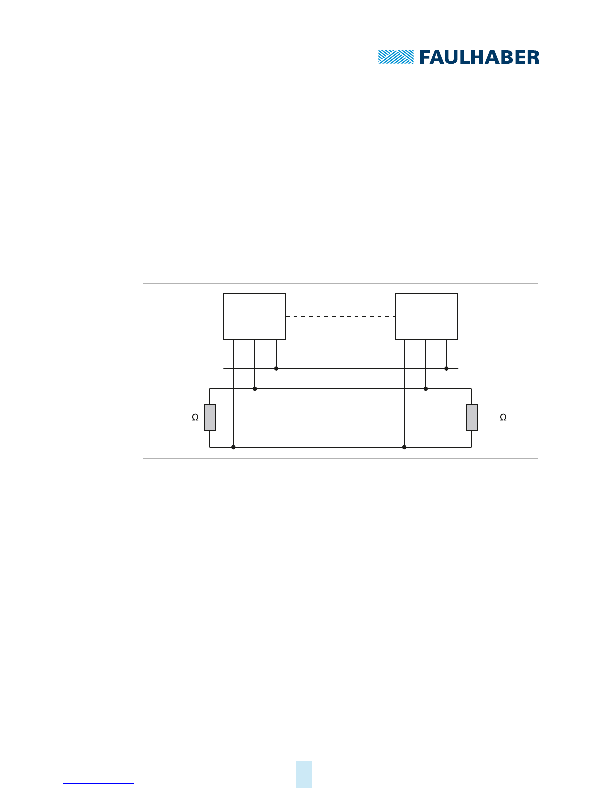
2.2 Pre-conditions for communication
FAULHABER drives are delivered in the unconfigured state. For operation in a CAN net-
work, a unique node number must be assigned and a Baud rate set at commissioning (see
chap. 5, p. 40).
After switching on and initialising, the Motion Controller is at first in the Pre-Operational
state. In order to be able to perform drive functions, the Motion Controller must be
brought into the Operational state (see chap. 3.8, p. 27).
1. Connect the controller to a power supply (supply at least to the electronics).
2. Connect CAN_H, CAN_L, GND to the respective terminals of a host-side CAN connection.
3. Switch on the power and establish a connection via the configuration application.
Fig. 2: Connection to the CANopen network
2.3 FAULHABER Motion Manager
We recommend that the first commissioning of a FAULHABER drive is performed using
“FAULHABER Motion Manager“ software.
The FAULHABER Motion Manager permits simple access to the settings and parameters of
the connected motor controller. The graphical user interface allows configurations to be
read, changed and reloaded. Individual commands or complete parameter sets and pro-
gram sequences can be input and loaded to the controller.
Wizard functions support the user when commissioning the drive controllers. The wizard
functions are arranged on the user interface in the sequence they are normally used:
Connection wizard: Supports the user when establishing the connection to the con-
nected controller
Motor wizard: Supports the user when configuring an external controller to the con-
nected motor, by selecting the respective FAULHABER motor
Control setting wizard: Supports the user in optimising the control parameters.
The software can be downloaded free of charge from the FAULHABER Internet page.
Node 1
CAN Bus Line
Node n
GND
CAN_H
CAN_L
120 120

4th edition, 9-11-2018 7000.05050, 4th edition, 9-11-20187000.05050
Overview
10
The FAULHABER Motion Manager is described in the separate “Motion Manager 6” man-
ual. The contents of the manual are also available as context-sensitive online help within
the FAULHABER Motion Manager.
2.4 Saving and restoring parameters
So that changed parameters in the OD remain active in the controller when it is switched
on again, the “Save” command must be executed to save them permanently in the non-vol-
atile memory (application EEPROM) (see chap. 6.1, p. 43). When the motor is switched on,
the parameters are loaded automatically from the non-volatile memory into the volatile
memory (RAM)
Fig. 3: Saving and restoring parameters
The following parameters can be loaded using the “Restore” command (see chap. 6.1,
p. 43):
Factory settings
Parameters saved using the “Save” command
2.4.1 Saving parameters
The current parameter settings can be saved in the internal EEPROM (SAVE) (see Tab. 21),
either completely or for individual ranges.
Write the “Save” signature to the subindex 01 to 05 of the object 0x1010 (see Tab. 22).
We recommend always using the latest version of the FAULHABER Motion Manager.
RAM EEPROM
Save command
Power Supply ON
or
Restore command
Device
control
Communication
command

4th edition, 9-11-2018 7000.05050, 4th edition, 9-11-20187000.05050
Overview
11
2.4.2 Restoring settings
Factory settings or last saved parameter settings can be loaded from the internal EEPROM
at any time, completely or for specific ranges (RESTORE) (see Tab. 23).
1. Write the “Load” signature to the subindex 01 to 06 of the object 0x1011 (see Tab. 24).
After Restore Factory (01), Restore Communication (02) and Restore Application
(03), the parameters are updated only after a reset.
2. Application parameters (04), together with record 1 and record 2 of the special applica-
tion parameters (05/06) can be updated with the “Reload” command.
The “Reload” command overwrites the values last saved as application parameters.
2.4.3 Changing the parameter set
The saved application parameters (motor data, I/O configuration, controller parameters,
operating mode etc.) contain a comprehensive basic set of parameters (App) and alongside
this there is a saved data area for parameters which often must be modified to cater for
variations in the load situation (App1/App2):
Speed controller and filter
Position controller
When the drive is next switched on, the saved parameters are loaded automatically.
If it is desired that the values currently loaded remain available after a “Restore”, these
must be saved to the PC using a suitable program (such as FAULHABER Motion Man-
ager).
Index Subindex Name Type Attr. Meaning
0x2344 0x01 Gain KPU32 rw Controller Gain [As 1e-6]
0x02 Integral time TN U16 rw Controller reset time [100 μs]
0x2346 0x01 Setpoint velocity filter time T_F U16 rw Filter time T_F [100 μs]
0x02 Setpoint Filter Enable U8 rw 0: inactive
1: active
0x2347 0x01 Gain factor U8 rw Gain factor (used by the velocity control-
ler in PP mode on the KP)
0: The gain factor of the speed controller
is reduced to 0 at the target
128: no variable gain
255: The gain factor of the speed control-
ler is doubled at the target
Index Subindex Name Type Attr. Meaning
0x2348 0x00 Number of entries U8 ro Number of object entries
0x01 Kv[1/s] U8 rw Range: 1-250

4th edition, 9-11-2018 7000.05050, 4th edition, 9-11-20187000.05050
Overview
12
Pre-controls
General settings
These parameters are stored twice. In operation the system can switch quickly between
these different pre-set values.
Index Subindex Name Type Attr. Meaning
0x2349 0x01 Torque/force feed forward factor U8 rw Factor for the torque or force control
0: 0% activation of the pre-control value
128: 100% pre-control
0x02 Torque/Force feed forward delay U8 rw Setpoint delay:
0: undelayed activation
1: Activation delayed by one sampling
0x234A 0x01 Velocity feed forward factor U8 rw Factor for the torque or force control
0: 0% pre-control
128: 100% pre-control
0x02 Velocity feed forward delay U8 rw Setpoint delay:
0: undelayed activation
1: Activation delayed by one sampling
Index Subindex Name Type Attr. Meaning
0x6060 0x00 Modes of operation S8 rw Select the operating mode
–4: ATC
–3: AVC
–2: APC
–1: Voltage Mode
0: Controller not activated
1: PP
3: PV
6: Homing
8: CSP
9: CSV
10: CST
0x6081 0x00 Profile Velocity U32 rw Profile velocity [in user-defined scaling]
0x6083 0x00 Profile acceleration U32 rw Profile acceleration [1/s2]
0x6084 0x00 Profile deceleration U32 rw Profile deceleration [1/s2]
0x6086 0x00 Motion Profile Type S16 rw Motion profile type:
0: Linear profile
1: Sin2velocity
0x60E0 0x00 Positive torque limit value U16 rw Value of the upper limit value [in relative
scaling]
0x60E1 0x00 Negative torque limit value U16 rw Value of the lower limit value [in relative
scaling]

4th edition, 9-11-2018 7000.05050, 4th edition, 9-11-20187000.05050
Overview
13
Create an application
SAVE application parameters 1: Write the “Save” signature to the subindex 04 of the
object 0x1010.
The current data are saved as the application parameter set 1.
SAVE application parameters 2: Write the “Save” signature to the subindex 05 of the
object 0x1010.
The current data are saved as the application parameter dataset 2.
Activate an application
Reload Application Parameters 1: Write the “Load” signature to the subindex 05 of the
object 0x1011.
Current data from the application parameter set 1 are activated directly.
Reload Application Parameters 2: Write the “Load” signature to the subindex 06 of the
object 0x1011.
Current data from the application parameter set 2 are activated directly.

4th edition, 9-11-2018 7000.05050, 4th edition, 9-11-20187000.05050
CANopen protocol description
14
3 CANopen protocol description
3.1 Introduction
CANopen
CANopen is a standard software protocol. A CAN hardware environment is required for
communication using CANopen. Up to 127 nodes can be addressed within a CANopen net-
work. The maximum transmission speed is 1 MBit/s.
CAN standardisation
The CiA defines the following aspects in CiA 301:
communications structure
Control and monitoring functions
CANopen device profiles have been defined for a wide range of device classes, such as:
CiA 402 for drives
CiA 401 for input and output devices
Structure of a CANopen telegram
A CANopen telegram has an 11-bit identifier and can contain up to 8 bytes of user data.
Tab. 1: Schematic structure of a CANopen telegram
11-bit identifier up to 8 bytes user data
11-bit 8-bit 8-bit 8-bit 8-bit 8-bit 8-bit 8-bit 8-bit
4th edition, 9-11-2018 7000.05050, 4th edition, 9-11-20187000.05050
CANopen protocol description
15
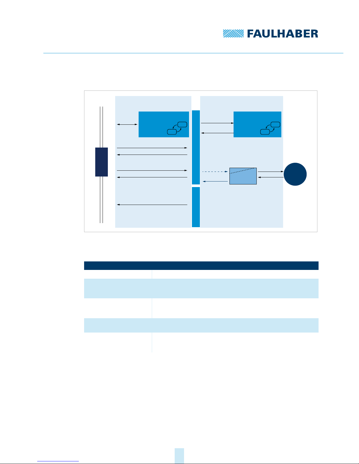
3.2 Communication services
Fig. 4: Communication services of the Motion Controller
The communication part contains communication services as specified in CiA 301.
Tab. 2: Communication services to CiA 301
Communications profile
FAULHABER Motion Controllers support the CANopen communications profile to
CiA 301 V4:
4 transmission PDOs
4 receipt PDOs
1 server SDO
Emergency object
NMT with node guarding and heartbeat
SYNC object
Communication services Description
NMT (Network Management) Activates nodes and monitors the current status of a node (see chap. 3.8, p. 27).
SDO (Service Data Object) The CANopen master uses the SDO to access parameters within a node. Each
SDO access reads or writes exactly one parameter. An SDO can only address one
node in a network (see chap. 3.5, p. 21).
PDO (Process Data Object) The PDO is used to access real-time data. A PDO can use a CAN message to
access multiple drive parameters concurrently. The parameters sent or received
in a PDO can be freely configured (see chap. 3.4, p. 17).
SYNC object SYNC objects are used to synchronise different applications on the CAN-BUS
(see chap. 3.7, p. 26).
EMCY (Emergency Object) An emergency message is used to inform the CANopen master about errors. A
CAN message conveys the error code asynchronously so that the status of the
CANopen slave need not be interrogated after an error (see chap. 3.6, p. 24).
Communication Application
Motor
CAN
n , Pos∗∗
Motor Control
Control Word
Status Word
n, Pos
EMCY
PDO1 … PDO4
SDO
CiA 301 CANopen
Statemachine
NMT
Guarding
CAN Bus
Error Handling Object Dictionary
CiA 402 Drive
Statemachine

4th edition, 9-11-2018 7000.05050, 4th edition, 9-11-20187000.05050
CANopen protocol description
16
3.3 Identifier distribution
The Communication Object Identifier (COB-ID) consists of a 7-bit node address (Node-ID)
and a 4-bit function code.
Fig. 5: Identifier distribution
The Predefined-Connection-Set defines the standard identifier for the most important
objects.
Tab. 3: Standard identifier
The COB-IDs of the PDOs, the SYNC objects and the emergency objects can be changed via
the communication parameters in the object dictionary. The COB-ID of the SDO telegram
cannot be changed and is always derived from the node number.
The data assignment of the PDOs is pre-set to the “PDO set for servo drive” as specified
in CiA 402 V3, but can be changed by the user (dynamic PDO mapping).
Object Function code
(binary)
Resulting COB-ID Object index for communica-
tion setting
NMT 0000 0 –
SYNC 0001 128 (80 h) 1005 h
EMERGENCY 0001 129 (81h) to 255 (FFh) 1014 h
PDO1 (tx) 0011 385 (181h) to 511 (1FFh) 1800 h
PDO1 (rx) 0100 513 (201h) to 639 (27Fh) 1400 h
PDO2 (tx) 0101 641 (281h) to 767 (2FFh) 1801 h
PDO2 (rx) 0110 769 (301h) to 895 (37Fh) 1401 h
PDO3 (tx) 0111 897 (381h) to 1023 (3FFh) 1802 h
PDO3 (rx) 1000 1025 (401h) to 1151 (47Fh) 1402 h
PDO4 (tx) 1001 1153 (481h) to 1279 (4FFh) 1803 h
PDO4 (rx) 1010 1281 (501h) to 1407 (57Fh) 1403 h
SDO (tx) 1011 1409 (581h) to 1535 (5FFh) 1200 h
SDO (rx) 1100 1537 (601h) to 1663 (67Fh) 1200 h
NMT error control 1110 1793 (701h) to 1919 (77Fh) –
Function
Code
10Bit-No.:
COB-Identifier Priority
0
Node-ID
0
10 high
low

4th edition, 9-11-2018 7000.05050, 4th edition, 9-11-20187000.05050
CANopen protocol description
17
3.4 PDO (Process Data Object)
PDOs are CAN messages with up to 8 bytes user data. PDOs contain process data for con-
trolling and monitoring the behaviour of the device. The drive makes the distinction
between receipt PDOs and transmission PDOs.
Receipt PDOs (RxPDO): are received by a drive and typically contain control data
Transmission PDOs (TxPDO): are sent by a drive and typically contain monitoring data
PDOs are evaluated or transmitted only when the device is in the NMT Operational state
(see chap. 3.8, p. 27).
The transmission of PDOs can be triggered in various different ways. The behaviour can be
set for each PDO via the transmission type parameter of the communication parameters in
the object dictionary:
Tab. 4: Types of PDO transmissions
As delivered the system is configured with the node number 1. The COB-IDs are pre-set
correspondingly:
RxPDO: 201h, 301h, 401h and 501h
TxPDO: 181h, 281h, 381h and 481h
EMCY: 81 h
RxSDO: 581 h
TxSDO: 601 h
If the node number is changed from 255 (unconfigured CANopen node) to a value
>127 using the LSS protocol, the COB-IDs which depend on this node number are auto-
matically adjusted.
Transmission Type Description
Event-driven Event-driven RxPDOs are processed immediately on receipt.
Event-driven TxPDOs are sent when the statusword of the device is contained and has
been changed.
Remote request (RTR) Data are sent in response to a request message.
Synchronised Data are sent after receipt of a SYNC object (see chap. 3.7, p. 26).

4th edition, 9-11-2018 7000.05050, 4th edition, 9-11-20187000.05050
CANopen protocol description
18
3.4.1 PDO configuration
A maximum of 4 parameters can be mapped in one PDO.
The data assignment of PDOs can be changed via the objects 0x1600 to 0x1603 and
0x1A00 to 0x1A03. The mapping procedure necessary for this is described in CiA 301. A
suitable tool (such as FAULHABER Motion Manager or System Manager for the PLC con-
troller than is used) is necessary for performance of the mapping procedure.
The transmission types and COB-ID of the PDOs can be changed via the objects 0x1400
to 0x1403 and 0x1800 to 0x1803.
The transmission type parameters can be used to change the behaviour of a PDO:
Tab. 5: Transmission type of a PDO
3.4.2 PDO mapping in the standard configuration (status as delivered)
RxPDO1: Controlword
The RxPDO1 contains the 16-bit controlword to CiA DSP402. The controlword controls the
state machine of the drive unit and points to the object index 0x6040 in the object diction-
ary. The bit distribution is described in the documentation for the drive functions.
TxPDO1: Statusword
The TxPDO1 contains the 16-bit statusword to CiA 402. The statusword indicates the status
of the drive unit an and points to the object index 0x6041 in the object dictionary. The bit
distribution is described in the documentation for the drive functions.
Transmission Type Meaning
0 synchronous, acyclical
A PDO is sent or executed once after a SYNC object when the contents of the PDO have
changed (see chap. 3.7, p. 26).
1 to 240 synchronous, cyclical
A PDO is sent after every SYNC object (see chap. 3.7, p. 26). The value is then equal to the
number of SYNC objects that must be received before the PDO is sent again (1 = PDO is
sent for every SYNC object)
252 TxPDOs only: asynchronous
On a SYNC signal, the contents of the TxPDO are stored
On request (RTR) the TxPDO is sent to the master
253 TxPDOs only: asynchronous
On request (RTR) the TxPDO is sent to the Master
255 asynchronous (event-driven)
11-bit identifier 2 bytes user data
0x200 (512d) +
node ID
LB HB
11-bit identifier 2 bytes user data
0x180 (384d) +
node ID
LB HB

4th edition, 9-11-2018 7000.05050, 4th edition, 9-11-20187000.05050
CANopen protocol description
19
RxPDO2: Controlword, target position (PP)
The RxPDO2 contains the 16-bit controlword and the 32-bit value of the destination posi-
tion (object 0x607A) for the Profile Position mode (PP).
TxPDO2: Statusword, Position Actual Value
The TxPDO2 contains the 16-bit statusword and the 32-bit value of the actual position
(object 0x6064).
RxPDO3: Controlword, target velocity (PV)
The RxPDO3 contains the 16-bit controlword and the 32-bit value of the set speed
(object 0x60FF) for the Profile Velocity mode (PV).
TxPDO3: Statusword, Velocity Actual Value
The TxPDO3 contains the 16-bit statusword and the 32-bit value of the actual speed (object
0x606C).
RxPDO4: Controlword, target torque
The RxPDO4 contains the 16-bit controlword and the 16-bit value of the target torque
(object 0x6071) for Cyclic Torque Mode (CST).
TxPDO4: Statusword, torque actual value
The RxPDO4 contains the 16-bit statusword and the 16-bit value of the actual torque
(object 0x6077) for Cyclic Torque mode (CST).
11-bit identifier 6 bytes user data
0x300 (768d) +
node ID
LB HB LLB LHB HLB HHB
11-bit identifier 6 bytes user data
0x280 (640d) +
node ID
LB HB LLB LHB HLB HHB
11-bit identifier 6 bytes user data
0x400 (1024d) +
node ID
LB HB LLB LHB HLB HHB
11-bit identifier 6 bytes user data
0x380 (896d) +
node ID
LB HB LLB LHB HLB HHB
11-bit identifier 6 bytes user data
0x400 (1024d) +
node ID
LB HB LLB LHB HLB HHB
11-bit identifier 6 bytes user data
0x380 (896d) +
node ID
LB HB LLB LHB HLB HHB

4th edition, 9-11-2018 7000.05050, 4th edition, 9-11-20187000.05050
CANopen protocol description
20
3.4.3 Dealing with mapping errors
If the mapping procedure specified in CiA 301 is not complied with, one of the following
SDO errors will be returned:
Tab. 6: SDO errors in response the incorrect mapping procedure
If the number of mapped objects is 0, the PDO will be flagged internally as invalid and will
not be operated.
3.4.4 Dummy Mappings
RxPDOs can be configured so that more than one participant can respond to them. In this
case it may be desirable that only part of the data contained in the PDO is evaluated in one
of the devices.
For data that are not used locally, Dummy Mapping on one of the data types that is used
can be entered in the PDO mapping table:
Example
An RxPDO contains the target positions for two axes.
Mapping for the node that should respond to the first target position:
0x160x.00 = 2
0x160x.01 = 0x607A0020
0x160x.02 = 0x00040020
Mapping for the node that should respond to the second target position:
0x160x.00 = 2
0x160x.01 = 0x00040020
0x160x.02 = 0x607A0020
SDO error Meaning Cause
0x06090030 General value range error The mapping parameter lies outside that specified in the map-
ping procedure.
0x06020000 Object not present in the object
dictionary
The value for the number of mapped objects is greater than
the number of valid entries in the respective subindexes for
the mapping parameter objects.
Other mapping errors are described in the SDO error table (see chap. 3.5.2, p. 23).
Index Type
0x0002 S8
0x0003 S16
0x0004 S32
0x0005 U8
0x0006 U16
0x0007 U32
Other manuals for MC 5010
3
This manual suits for next models
3
Table of contents
Other Faulhaber DC Drive manuals

Popular DC Drive manuals by other brands

Dorner
Dorner 3200 Series Installation, maintenance & parts manual

Danfoss
Danfoss VLT HVAC Drive FC 102 operating instructions

GFA
GFA ELEKTROMAT SI 75.20 FU-55,00 installation instructions

Invertek Drives
Invertek Drives Optidrive ODE-2-12005-1H01 01 Series user guide

Leadshine Technology
Leadshine Technology DM432 user manual

ABB
ABB ACH580 Series Quick start up guide


