Faulhaber AEMT-12 L User manual

WE CREATE MOTION
Technical Manual
Multiturn Absolute encoder
AEMT-12/16 L
EN

Imprint
2
Version:
1st edition, 17-09-2020
Copyright
by Dr. Fritz Faulhaber GmbH & Co. KG
Daimlerstr. 23 / 25 · 71101 Schönaich
All rights reserved, including those to the translation.
No part of this description may be duplicated, reproduced,
stored in an information system or processed or
transferred in any other form without prior express written
permission of Dr. Fritz Faulhaber GmbH & Co. KG.
This document has been prepared with care.
Dr. Fritz Faulhaber GmbH & Co. KG cannot accept any
liability for any errors in this document or for the
consequences of such errors. Equally, no liability can be
accepted for direct or consequential damages resulting
from improper use of the equipment.
The relevant regulations regarding safety engineering
and interference suppression as well as the requirements
specified in this document are to be noted and followed
when using the software.
Subject to change without notice.
The respective current version of this technical manual is
available on FAULHABER's internet site:
www.faulhaber.com
1st edition, 17-09-2020 7000.05070, 1st edition, 17-09-20207000.05070

1st edition, 17-09-2020 7000.05070, 1st edition, 17-09-20207000.05070
Content
3
1 About this document ....................................................................................................... 4
1.1 Validity of this document ...................................................................................... 4
1.2 Associated documents ............................................................................................ 4
1.3 Using this document .............................................................................................. 4
1.4 List of abbreviations ............................................................................................... 5
1.5 Symbols and designations ...................................................................................... 5
2 Safety ................................................................................................................................ 6
2.1 Intended use ........................................................................................................... 6
2.2 Safety instructions .................................................................................................. 6
2.3 Environmental conditions ...................................................................................... 7
2.4 EC directives on product safety ............................................................................. 7
3 Product description .......................................................................................................... 8
3.1 General product description .................................................................................. 8
3.2 Product information ............................................................................................... 8
3.3 Product variants - Resolution ................................................................................. 9
3.4 Interpretation of position values and handling of position overrun ................ 10
3.5 Description of the interface ................................................................................. 11
4 Installation ...................................................................................................................... 12
4.1 Mounting .............................................................................................................. 12
4.1.1 Mounting instructions .......................................................................... 12
4.1.2 Mounting the motor............................................................................. 13
4.1.3 Load of the connection cables ............................................................. 13
4.2 Electrical connection ............................................................................................ 14
4.2.1 Notes on the electrical connection ...................................................... 14
4.2.2 Pin assignment ...................................................................................... 14
4.2.3 Electrical data........................................................................................ 15
4.2.4 Electrical circuit diagrams and external wiring ................................... 16
4.2.4.1 Line driver interface .............................................................. 16
4.2.4.2 Preset input ............................................................................ 18
4.2.4.3 Connecting battery supply .................................................... 18
4.3 Electromagnetic compatibility (EMC) .................................................................. 19
4.3.1 Cable routing ........................................................................................ 19
4.3.2 Shielding ................................................................................................ 21
4.3.3 Establishing the shield connection ...................................................... 22
4.3.4 Establishing shield connection with cable lug .................................... 23
4.4 Commissioning and battery change .................................................................... 24
4.5 Troubleshooting ................................................................................................... 25
5 Accessories ...................................................................................................................... 26
6 Binary numbers with and without sign ........................................................................ 27
7 Warranty ......................................................................................................................... 28

1st edition, 17-09-2020 7000.05070, 1st edition, 17-09-20207000.05070
About this document
4
1 About this document
1.1 Validity of this document
This document describes the installation and use of the following series:
AEMT-12/16 L
This document is intended for use by trained experts authorised to perform installation and
electrical connection of the product.
All data in this document relate to the standard versions of the series listed above. Changes
relating to customer-specific versions can be found in the corresponding data sheet.
1.2 Associated documents
For certain actions during commissioning and operation of FAULHABER products additional
information from the following manuals is useful:
These manuals can be downloaded in pdf format from the web page
www.faulhaber.com/manuals.
1.3 Using this document
Read the document carefully before undertaking commissioning.
Retain the document throughout the entire working life of the product.
Keep the document accessible to the operating and, if necessary, maintenance person-
nel at all times.
Pass the document on to any subsequent owner or user of the product.
Manual Description
Motion Manager 6 Operating instructions for FAULHABER Motion Manager PC software
Quick start guide Description of the first steps for commissioning and operation of FAULHABER Motion
Controllers
Drive functions Description of the operating modes and functions of the drive
Accessories manual Description of the accessories

1st edition, 17-09-2020 7000.05070, 1st edition, 17-09-20207000.05070
About this document
5
1.4 List of abbreviations
1.5 Symbols and designations
CAUTION!
Hazards due to hot surfaces. Disregard may lead to burns.
Measures for avoidance
NOTICE!
Risk of damage.
Measures for avoidance
Pre-requirement for a requested action
1. First step for a requested action
Result of a step
2. Second step of a requested action
Result of an action
Request for a single-step action
Abbreviation Meaning
AE Absolute encoder
BiSS-C Bidirectional, serial, synchronous interface in continuous mode
L Line Driver
MT Multiturn
PRE Interface pin
SSI Synchronous Serial Interface for Position Encoder
UBat Battery voltage
UDD Power supply
Instructions for understanding or optimising the operational procedures

1st edition, 17-09-2020 7000.05070, 1st edition, 17-09-20207000.05070
Safety
6
2 Safety
2.1 Intended use
The encoder described here has been designed as a sensor system that delivers angle infor-
mation used for actuating and positioning the following motors:
Brushless DC-servomotors
The encoder is suitable in particular for tasks in the following fields of application:
Robotics
Toolbuilding
Automation technology
Industrial equipment and special machine building
Medical technology
Laboratory technology
The following aspects must be taken into consideration when using an encoder:
The encoder contains electronic components and should be handled in accordance with
the ESD regulations.
Do not use the encoder in environments where it will come into contact with water,
chemicals and/or dust, nor in explosion hazard areas.
The encoder should be operated only within the limits specified in the data sheet.
Please ask the manufacturer for information about use under individual special
environmental conditions.
2.2 Safety instructions
NOTICE!
Electrostatic discharges can damage the electronics.
Wear conductive work clothes.
Wear an earthed wristband.
NOTICE!
Inserting and withdrawing connectors whilst supply voltage is applied at the device can
damage the electronics.
Do not insert or withdraw connectors whilst supply voltage is applied at the device.

1st edition, 17-09-2020 7000.05070, 1st edition, 17-09-20207000.05070
Safety
7
2.3 Environmental conditions
Select the installation location so that clean dry air is available for cooling the motor.
When installed within housings and cabinets take particular care to ensure adequate
cooling of the motor.
Select a power supply that is within the defined tolerance range.
Protect the encoder and motor against heavy deposits of dust, in particular metal dust
and chemical pollutants.
Protect the encoder and motor against humidity and wet.
2.4 EC directives on product safety
Machinery Directive (2006/42/EC)
Because of their small size, no serious threats to life or physical condition can normally be
expected from electric miniature drives. Therefore the Machinery Directive does not apply
to our products. The products described here are not “incomplete machines”. Therefore
installation instructions are not normally issued by FAULHABER.
Low Voltage Directive (2014/35/EU)
The Low Voltage Directive applies for all electrical equipment with a nominal voltage of 75
to 1500 V DC and 50 to 1000 V AC. The products described in this technical manual do not
fall within the scope of this directive, since they are intended for lower voltages.
EMC Directive (2014/30/EU)
The directive concerning electromagnetic compatibility (EMC) applies to all electrical and
electronic devices, installations and systems sold to an end user. In addition, CE marking can
be undertaken for built-in components according to the EMC Directive. Conformity with
the directive is documented in the Declaration of Conformity.
RoHS Directive (2011/65/EU)
The directive restricts the use of certain hazardous materials in electrical and electronic
devices. The products described in this technical manual fall within the scope of this direc-
tive. Conformity with the directive is documented in the EC Declaration of Conformity.
WEEE Directive (2012/19/EU)
The directive on the disposal of electrical and electronic devices prescribes the separate col-
lection of old electrical and electronic devices. The products described in this technical man-
ual fall within the scope of this directive.

1st edition, 17-09-2020 7000.05070, 1st edition, 17-09-20207000.05070
Product description
8
3 Product description
3.1 General product description
The AEMT-12/16 L series encoder is a magnetic multiturn absolute encoder.
The encoder provides the absolute angle information within one revolution (singleturn
position) and the current revolution count (multiturn count). The absolute position, relative
to the entire drive system, can be determined from the multiturn count and the singleturn
position.
The encoder is connected to a main power supply (5 V) as well as a backup battery or alter-
native energy storage. If the main power supply is switched off, the backup battery will still
provide the encoder with enough energy to detect motor revolutions and increment or
decrement the multiturn count accordingly. This way, when switching on the main supply
again, the count is still valid. A new reference run is not necessary. The backup battery is
not part of the encoder, and must be connected externally.
In combination with brushless DC-servomotors, the AEMT-12/16 L delivers absolute angle
information with a multiturn resolution of 16 bits and a singleturn resolution of 12 bits for
commutation, speed control and motion control. This position data can be queried by a SSI
Interface with BiSS-C Protocol. The interface is designed differentially and is based on the
RS422 standard.
The multiturn count can be reset on the hardware side via an additional interface pin (pre-
set) by a voltage pulse during start-up.
3.2 Product information
Fig. 1: Designation key
MTAE 12/16 L
–
Singleturn resolution
Line Driver
Absolute encoder
Multiturn
Multiturn resolution

1st edition, 17-09-2020 7000.05070, 1st edition, 17-09-20207000.05070
Product description
9
3.3 Product variants - Resolution
The encoder has a standard singleturn resolution of 12 bit (4096 increments per revolution)
and a multiturn resolution of 16 bit. Thus, 216 = 65536 revolutions can be counted.
Apart from the standard configuration, other resolutions are available as special program-
ming on request (see Tab. 1).
Tab. 1: Available singleturn and multiturn resolutions
Singleturn resolution Multiturn resolution
10 bit 12 bit
11 bit 16 bit
12 bit 20 bit
24 bit
32 bit
In combination with a FAULHABER Motion Controller of Generation V3.0, an overall
resolution (multiturn + singleturn) of maximum 32 bit is possible.
With an singleturn resolution of 12 bits, a maximum multiturn resolution of 20 bits
is possible.
With an singleturn resolution of 10 bits, a maximum multiturn resolution of 20 bits
is possible.
1st edition, 17-09-2020 7000.05070, 1st edition, 17-09-20207000.05070
Product description
10
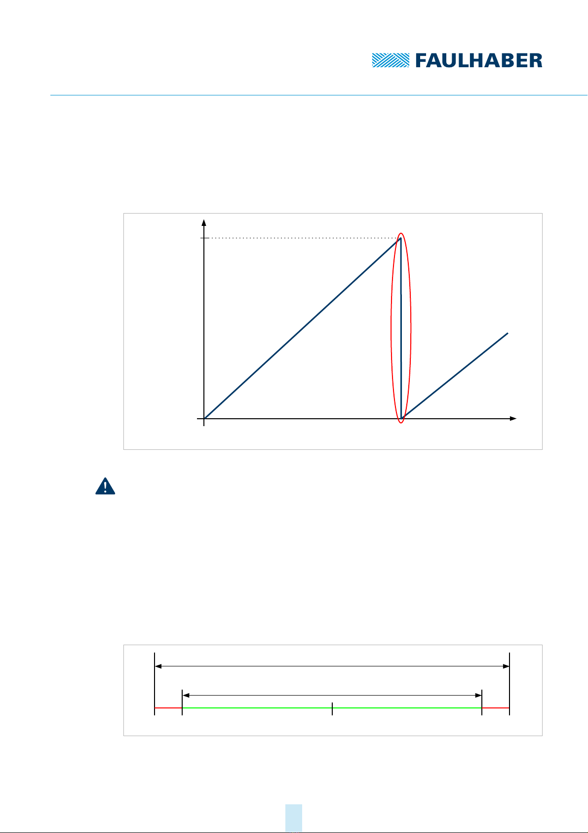
3.4 Interpretation of position values and handling of position over-
run
In the standard configuration of the AEMT-12/16 L, there is a number range from 0 to
268 435 455 positions (216 ∙212 – 1). Then the count starts again from the beginning.
Fig. 2: Position overrun at the range limit
NOTICE!
Damage to mechanics
Positioning exceeding the position overrun leads to a loss of information of the absolute po-
sition and can damage the mechanics.
Ensure that the application travel is within the range limits of the maximum travel.
During commissioning and after a battery change, reset the revolution count of the
encoder using the preset pin, see chap. 4.4, p. 24. By interpreting the data values with
sign (signed), positioning can then be made in both directions of rotation up to the
overrun, see chap. 6, p. 27.
Position limits can be defined (LL, UL) in the controller, which cannot be overrun, see
Fig. 3.
Fig. 3: Limitation of the travel distance when evaluating the binary data with sign
(signed)
Multiturn
resolution
Mechanical
revolution
Position
overflow
–227 +2 27
Preset ULLL
Maximum movement distance
Limited movement distance
1st edition, 17-09-2020 7000.05070, 1st edition, 17-09-20207000.05070
Product description
11
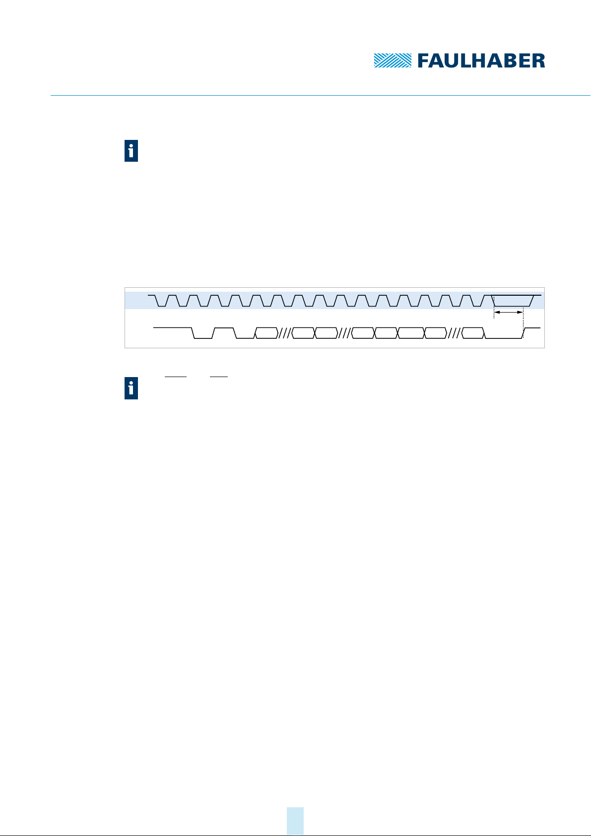
3.5 Description of the interface
Fig. 4: Interface signals
The angle information for the singleturn and multiturn position can be queried via a serial
interface with BISS-C protocol. In this case, CLK is the input for the clock signal of the serial
interface. The data of the serial interface is available on the Data line.
The start sequence consists of an acknowledge bit (Ack), a start bit and a control bit (CDS).
All data values are transmitted with the most significant bit first, starting with the
multiturn position (MT15…MT0), followed by the singleturn position (ST11…ST0). This is
followed by an error bit (nERR), a warning bit (nWARN) and 6 CRC bits (CRC5…CRC0).
The error bit is set e.g. by a low battery voltage (see chap. 4.4, p. 24).
The warning bit is activated when the maximum allowed speed is exceeded. nERR and
nWARN are low-active.
If no further clock signals are sent, the encoder enters a timeout after 20 μs, causing com-
munication to be ended. The maximum clock frequency is 2 MHz.
For further information on the BISS-C protocol, see: https://biss-interface.com/c/downloads.
The value to which the count of the encoder is reset via the preset pin is not unambig-
uously 0, but instead lies within a range of ±8192 increments, depending on the
singleturn position.
The preset value is set at the factory to a signed interpretation of the position data, see
chap. 6, p. 27. If the position data should be interpreted without sign (unsigned),
another preset value can be set at the factory.
The Data and CLK signals are inverted in relation to the shown Data and CLK signals.
CLK
Data Ack Start CDS MT15 CRC5 CRC0 StopMT0 ST11 ST0 nERR nWARN
Timeout

1st edition, 17-09-2020 7000.05070, 1st edition, 17-09-20207000.05070
Installation
12
4 Installation
Only trained experts and instructed persons with knowledge of the following fields may
install and commission the encoder:
Automation technology
Standards and regulations (such as the EMC Directive)
Low Voltage Directive
Machinery Directive
VDE regulations (DIN VDE 0100)
Accident prevention regulations
This description must be carefully read and observed before commissioning.
Also comply with the supplementary instructions for installation (see chap. 2.3, p. 7).
4.1 Mounting
4.1.1 Mounting instructions
CAUTION!
The motor can become very hot during operation.
Place a guard against contact and warning notice in the immediate proximity of the
motor.
Ensure that adequate heat dissipation is provided.
NOTICE!
Installation and connection of the motor when the power supply is applied can damage the
device.
Prior to all aspects of installation and connection work on the motor, switch off the
power supply.
1st edition, 17-09-2020 7000.05070, 1st edition, 17-09-20207000.05070
Installation
13
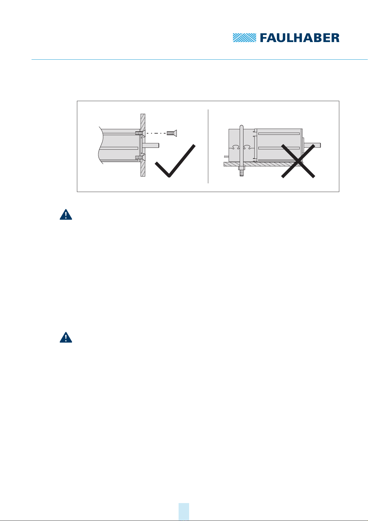
4.1.2 Mounting the motor
Fig. 5: Mounting example – 22xxBX4 AEMTL series
NOTICE!
Excessive radial loads on the servomotor or excessively tightened fastening screws can
cause irreparable damage to the mounting flange.
Do not apply a radial force exceeding 30 N at the rear end of the motor.
Make sure that the screws are tightened to max. 50 Ncm.
Make sure that the screws are of sufficient strength.
1. Secure the front flange of the motor to a suitable surface using fastening screws.
2. Protect the fastening screws to prevent displacement due to the effect of heat.
3. If necessary, attach parts to the motor shaft.
4.1.3 Load of the connection cables
NOTICE!
Extreme static or dynamic loads on the ribbon cable can cause the cable to be damaged.
Make sure that the ribbon cable is not subjected to abrasion, crushing or excessively
tight bending radii during installation and operation.
With frequent bending, the bending radius must not be less than 10 mm. The possible
number of bending cycles increases as the bending radius increases.
Do not bend the cable at temperatures < –10 °C.
Comply with permissible loads.
Permissible loads of the ribbon cable:
Tensile load: <30 N
Continuous tensile load: <17 N
Bending radius with one-off installation: >1.2 mm

1st edition, 17-09-2020 7000.05070, 1st edition, 17-09-20207000.05070
Installation
14
4.2 Electrical connection
4.2.1 Notes on the electrical connection
NOTICE!
Installation and connection of the encoder when the power supply is applied can damage
the encoder.
Prior to all aspects of installation and connection work on the encoder, switch off the
power supply.
NOTICE!
Electrostatic discharges to the encoder connections can damage the electronic components.
Observe the ESD protective measures.
NOTICE!
Incorrect connection of the wires can damage the electronic components.
Connect the wires as shown in the connection assignment.
4.2.2 Pin assignment
Tab. 2: Pin assignment of ribbon cable (contact spacing: 1.27 AWG28)
Wire Designation Meaning
1 a)
a) Wire 1 is highlighted in a different colour
Pre Preset: Digital input for resetting the revolu-
tion count
2 UDD Power supply
3 GND Ground connection / battery connection (–)
4 UBAT Battery connection (+)
5 – Reserved
6 – Reserved
7Data Data (logically inverted signal)
8Data Data
9CLK Clock (logically inverted signal)
10 CLK Clock
1
23 4 56 7 8 9
10

1st edition, 17-09-2020 7000.05070, 1st edition, 17-09-20207000.05070
Installation
15
4.2.3 Electrical data
Tab. 3: Encoder supply
Tab. 4: Line driver interface with power supply switched on Udd
Tab. 5: Preset with power supply switched on Udd
Tab. 6: Battery mode
Power supply Udd 4.5…5.5 V
Rated current consumptiona)
a) Udd = 5 V on non-loaded outputs
Typical: 25 mA
Maximum: 35 mA
Standby current under loadb)
b) Udd = 5 V, terminating resistors RT= 120 Ωbetween CLK and CLK (integrated in the encoder) and between
Data and Data, current measurement in ground path
Typical: 90 mA
Set-up time after power on 20 ms
Parameter Value
Input low level (CLK, CLK) 0…0.8 V
Input high level (CLK, CLK)2…5 V
Driver capability See RS422
Timeout Typical: 20 μs
Parameter Value
Input high levela)
a) Udd = 5 V
4.25…5 V
Input low level 0…2 V
Preset duty cycle, minimum 100 ms
At the preset pin, a voltage of at least 4.25 V must be applied to reset the multiturn
count.
To prevent unintentional resetting, the voltage must not exceed 2 V.
Parameter Value
Battery voltage UBat 3.0…5.5 V
Power consumption in battery modea)
a) UBat = 3.6 V, in standstill (n = 0 rpm)
10 μA
Maximum permissible acceleration in battery mode 48 ∙103rad/s2
Maximum permissible speed in battery mode 16 000 rpm
For a battery voltage UBat < 2.8 V the nERROR error bit is set in the BiSS-C protocol,
see chap. 3.5, p. 11.
As an option, the maximum permissible acceleration can be adjusted at the factory.
The power consumption increases with increasing maximum permissible accelera-
tion.

1st edition, 17-09-2020 7000.05070, 1st edition, 17-09-20207000.05070
Installation
16
NOTICE!
Damage to mechanics
Exceeding the maximum permissible acceleration or speed while in battery mode may result
in an invalid revolution count and result in damage to the mechanics.
When designing, take into account the maximum possible acceleration of the applica-
tion.
For higher accelerations use a special configuration of the encoder.
4.2.4 Electrical circuit diagrams and external wiring
4.2.4.1 Line driver interface
The encoder has a line driver interface based on the RS422 standard. A terminating resistor
RT=120Ωis integrated between the input signals CLK and CLK .
Fig. 6: Electrical circuit diagram of the encoder signals and connection to a line driver
transceiver
When connecting the line driver interface on the controller side:
Use transceiver module.
The transceiver is already integrated in FAULHABER Motion Controllers of genera-
tion V3.0.
Recommended transceiver components: iC-HF, SN65LBC179, SN75179B, DS90LV019
Use a terminating resistor between data and data starting at a cable length of 1 m.
For the termination options of signals data and data see Fig. 7
Encoder
internal
UDD
CLK
Data
GND
CLK
Data
RT
Transceiver
UDD
GND
RT
Transmitter
Receiver
Controller
UDD
GND
CLK
Data

1st edition, 17-09-2020 7000.05070, 1st edition, 17-09-20207000.05070
Installation
17
Fig. 7: Termination types
Standard: Terminating resistor RT= 100…130 Ω
Split termination: The terminating resistor is split symmetrically (e. g. RT1 = RT2 = 60 Ω).
The capacitor C (4.7...10 nF) discharges common-mode currents to ground. This leads to
an increased interference resistance of the signal transmission.
AC termination: A capacitor C in series with the terminating resistor RTcan reduce the
power consumption and thus the power loss in RT. The value of the capacitor must be
adjusted to the clock frequency.
With twisted-pair cables, proper cable routing and shielding, transmission lengths of 5 m
and more are possible, see chap. 4.3, p. 19.
1Standard
2 Split termination
3 AC termination
When selecting the terminating resistor RT, the power loss has to be considered. With a
terminating resistor RTof 120 Ω, a power loss of PV= U2/RT= (5 V)2/120 Ω≈0,21 W
results for the termination types (1) and (2), for example.
Data
Data
RT
Data
Data
RT1
RT2
C
Data
Data
RT
C
123
1st edition, 17-09-2020 7000.05070, 1st edition, 17-09-20207000.05070
Installation
18
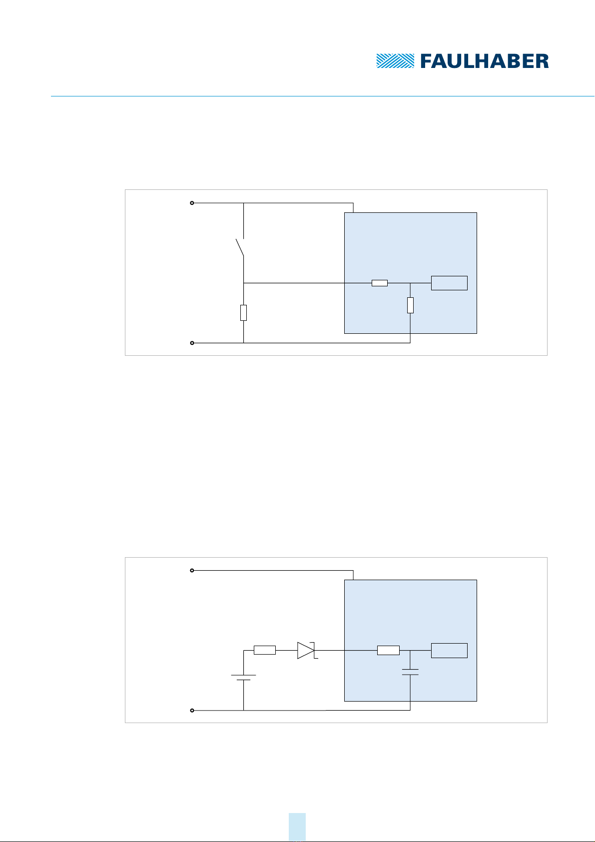
4.2.4.2 Preset input
During commissioning and after a battery change, a voltage pulse must be applied to the
preset input (pin 1) to reset the revolution count.
Fig. 8: Preset electrical circuit diagram
Provide mechanical switches, see Fig. 8.
Alternatively: Connect the preset pin to a digital output of a controller.
Connect the preset pin to ground externally using a pull-down resistor to ensure a
defined voltage of <2 V even with long cable lengths.
4.2.4.3 Connecting battery supply
Integrate the battery either in the extension of the supply line or in the customer-spe-
cific peripherals.
Connect the battery between pins UBATand GND.
In case of an error (e.g. short-circuit between UDD and UBAT) the resistor RV1 integrated
in the encoder limits the (reverse) current into the battery.
Fig. 9: Battery connection option
Encoder
internal
UDD
GND
Dig-In
Pre
Switch
1...4.7 kW
Encoder
internal
UDD
GND
Sensor
C
Battery
R
V1
= 300 W
UBAT
R
V2
D1
+
–

1st edition, 17-09-2020 7000.05070, 1st edition, 17-09-20207000.05070
Installation
19
NOTICE!
Damage to battery
In case of an error, an unacceptable charging current (reverse current) can damage the bat-
tery. The UL1642 and IEC60086-4 standards describe recommendations for the safety of lith-
ium batteries.
When selecting the battery, check the dimensions of the integrated resistor RV1 based
on the maximum permissible reverse current.
If necessary, connect another series resistor RV2 and/or a D1 diode in series with the bat-
tery.
Install additional protective components (D1, RV2) close to the battery.
4.3 Electromagnetic compatibility (EMC)
Follow the instructions in the following chapters and in the technical manual of the
FAULHABER Motion Controller of generation V3.0 to perform an EMC-compliant instal-
lation.
4.3.1 Cable routing
The cable routing depends on various factors, such as:
Is the cable shielded, twisted?
Were interference-reducing measures taken?
What material and what cable routing are used in the cable duct?
Over what surface is the cable routed?
Observe the following when laying the cables:
Use a full-surface, u-shaped and, if possible, metal cable duct.
Lay the cables near the corners of the cable duct.
Separate the cables by function where possible.
Maintain distances when laying the cables.
The distances may vary depending on the zone in the switching cabinet.
If possible, all cables should be twisted pairs or twisted and shielded in function groups
(e.g., motor phases together, encoder cables together).
Fig. 10: Laying in the cable duct
Depending on the type of energy storage and the requirements on the service life,
more complex circuits may be required for battery management.
1
2
3

1st edition, 17-09-2020 7000.05070, 1st edition, 17-09-20207000.05070
Installation
20
Fig. 11: Grouping and shielding of the cables
Fig. 12: Cables twisted and shielded in function groups for connection of BL servomotor
with AEMT-12/16 L
1 Shielding
2 Motor phase
3 Encoder cables
1
>10 cm
23123123
1 1
1
Cable Shield
Motor A Phase A
Data
CLK
Motor B Phase B
U
DD
Data
Motor C Phase C
Brushless
DC-Servomotor
GND
Cable Shield
CLK
PRE
U
BAT
This manual suits for next models
1
Table of contents
Popular Media Converter manuals by other brands


H&B
H&B TX-100 Installation and instruction manual

Bolin Technology
Bolin Technology D Series user manual

IFM Electronic
IFM Electronic Efector 400 RN30 Series Device manual

GRASS VALLEY
GRASS VALLEY KUDOSPRO ULC2000 user manual

Linear Technology
Linear Technology DC1523A Demo Manual

Lika
Lika ROTAPULS I28 Series quick start guide

Weidmuller
Weidmuller IE-MC-VL Series Hardware installation guide

Optical Systems Design
Optical Systems Design OSD2139 Series Operator's manual

Tema Telecomunicazioni
Tema Telecomunicazioni AD615/S product manual

KTI Networks
KTI Networks KGC-352 Series installation guide

Gira
Gira 0588 Series operating instructions

Lika
Lika SFA-5000-FD user guide