FC LIGHTING FCSL101-FCSL106 User manual

t800.900.1730 f630.889.8106
3609 Swenson Ave. St. Charles, IL 60174
Apply Silicone Bead
THIS DOCUMENT IS PROPRIETARY TO FC LIGHTING, INC. ANY UNAUTHORIZED TRANSFER, USE OR REPRODUCTION IS STRICTLY PROHIBITED. ©2016 FC LIGHTING, INC.
FCSL100 SERIES - INSTALLATION INSTRUCTIONS page 1 of 2
CAUTION: BEFORE CONNECTING THE FIXTURE TO A POWER SUPPLY, MAKE SURE THE POWER IS SWITCHED OFF.
NOTE: Faceplates - The Faceplate type used determines xture installation.
FCSL101-FCSL106 mounts ush to front of Fixture Lip. (Fig.1) and B(HB)
FCSL108-FCSL110 ts over (wraps around) Fixture Lip. (Fig. 2) and C(DWR)
GENERAL:
1. Before starting the installation, make sure all electricity has been turned off and electrical
breaker has been locked out and tagged out.
2. To ensure the success of the installation, be sure to read these instructions and review the
diagrams thoroughly before beginning.
3. All electrical connections must be in accordance with local codes, ordinances, or the
National Electrical Code.
NOTE: The important safeguards and instructions appearing in this manual are not meant to
cover all possible conditions and situations that may occur.
INSTALLATION INSTRUCTIONS:
A) Remove the two (2) socket head screws holding Lens and Faceplate to xture. Then remove
internal lamping components (guts) from xture.
FOR CONCRETE POUR: Be sure to level and stabilize xture. Cover any holes and knockouts on
xture housing to prevent leakage. Seal the xture to prevent water leakage during operation.
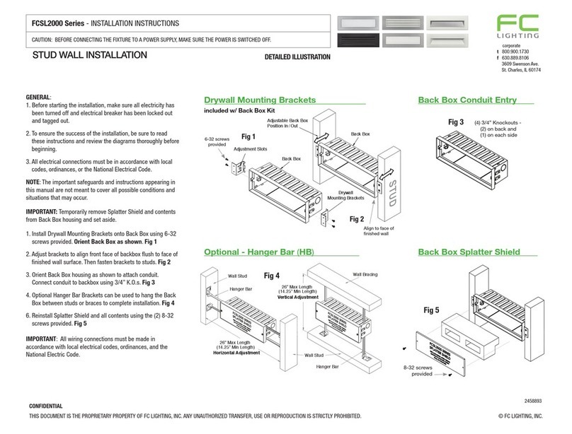
FOR DRYWALL MOUNT: Cut hole in drywall (2-5/8” x 9-3/8”) for ush mount Bor
(2-5/16” x 8-5/16”) for front mount C. Refer to detailed instructions on page 2.
NOTE: PL version is not for through wiring. All connections must be water tight.
1) Connect conduit or code approved electrical tting through one of the 7/8” diameter holes
on the back or side of the xture. Secure xture housing to forms outside of gasket area.
Refer to Fig. 3 on pg. 2 using Hanger Brackets and Drywall Adapters for Front Mounted
drywall application.
2) After xture is mounted, connect your ground wire to green ground wire on xture.
3) Replace internal components with approved lamp.
4) Attach lens and frame, replace two (2) socket screws tightening evenly.
5) Restore power and test xture. If xture does not turn on, disconnect power before
checking for problems.
IMPORTANT: Fixtures are listed for installation with liquid tight or rigid wall conduit only.
DFixtures installed without a silicone bead will void the warranty.
DETAILED ILLUSTRATION
JO Rev. 0218
Fig. 3
Drywall Adapter
(DWR)
Drywall Adapter
Tighten
Screw
Adapter holds
Fixture in place.
Adapter Screw
Back of Fixture
Front of Fixture Lip Mounted Flush with Wall.
Use HB for proper installation.
Fixture Lip Mounted in Front of Wall.
Use DWR for proper installation
Fixture Lip in Wall
Same for concrete or drywall application.
Same for concrete or drywall application.
Fixture Lip against Wall
Fixture Lip
Gasket Area
A
B
C
Mounting for Fig.1 Faceplate type.
Mounting for Fig.2 Faceplate type.
BOSS REQUIRED FOR GROUND SCREW.
8MM OD X 8MM TALL BLIND TAP 6-32, 8MM DEEP
2.64 in
INSERT TYP2
8-32 THREADED
2.8 in
BLIND HOLE TYP 4
3 X 6MM DEEP
22.23 TYP 2 2 x 1MM DEEP
TYP 2
.125 in
9.375 in
3 in.
BOSS REQUIRED FOR GROUND SCREW.
8MM OD X 8MM TALL BLIND TAP 6-32, 8MM DEEP
2.64 in
INSERT TYP2
8-32 THREADED
2.8 in
BLIND HOLE TYP 4
3 X 6MM DEEP
22.23 TYP 2 2 x 1MM DEEP
TYP 2
.125 in
9.375 in
3 in.
Fig.1 Faceplate mounts to
Front of Fixture Lip.
Use mounting B
Fig. 2
Faceplate ts
over Fixture Lip.
Use mounting C
Fixture Lip
BOSS REQUIRED FOR GROUND SCREW.
8MM OD X 8MM TALL BLIND TAP 6-32, 8MM DEEP
2.64 in
INSERT TYP2
8-32 THREADED
2.8 in
BLIND HOLE TYP 4
3 X 6MM DEEP
22.23 TYP 2 2 x 1MM DEEP
TYP 2
.125 in
9.375 in
3 in.
Back of Fixture
1/2” trade connector openings
Fixture Lip
Fixture Housing
BOSS REQUIRED FOR GROUND SCREW.
8MM OD X 8MM TALL BLIND TAP 6-32, 8MM DEEP
2.64 in
INSERT TYP2
8-32 THREADED
2.8 in
BLIND HOLE TYP 4
3 X 6MM DEEP
22.23 TYP 2 2 x 1MM DEEP
TYP 2
.125 in
9.375 in
3 in.
D
Apply Silicone Bead
D

t800.900.1730 f630.889.8106
3609 Swenson Ave. St. Charles, IL 60174
Tighten
Screw
Adapter holds
Fixture in place.
Drywall Adapter
Adapter Screw
THIS DOCUMENT PROPRIETARY TO FC LIGHTING, INC. ANY UNAUTHORIZED TRANSFER, USE OR REPRODUCTION IS STRICTLY PROHIBITED. ©2016 FC LIGHTING, INC.
FCSL100 SERIES - INSTALLATION INSTRUCTIONS - page 2 of 2
CAUTION: BEFORE CONNECTING THE FIXTURE TO A POWER SUPPLY, MAKE SURE THE POWER IS SWITCHED OFF.
NOTE: Faceplates - The Faceplate type used determines xture installation.
FCSL101-FCSL106 mounts ush to front of Fixture Lip. (Fig.1) and B(HB)
FCSL108-FCSL110 ts over (wraps around) Fixture Lip. (Fig. 2) and C(DRW)
GENERAL:
1. Before starting the installation, make sure all electricity has been turned off and electrical
breaker has been locked out and tagged out.
2. To ensure the success of the installation, be sure to read these instructions and review the
diagrams thoroughly before beginning.
3. All electrical connections must be in accordance with local codes, ordinances, or the
National Electrical Code.
NOTE: The important safeguards and instructions appearing in this manual are not meant to
cover all possible conditions and situations that may occur.
DETAILED INSTRUCTIONS FOR FOR DRYWALL MOUNT USING HANGER BRACKET OR
DRYWALL ADAPTER (READ PAGE 1 OF INSTALLATION INSTRUCTIONS FIRST):
Flush mount Busing Hanger Bracket, New Construction, dry or damp locations only.
NOTE: PL version is not for through wiring. All connections must be water tight.
1) Locate xture between studs: 14.25” min to 22” max spacing between studs.
2) Mark height location of bottom edge of step light on vertical studs. Place second mark
at 1/4” below this mark.
3) With the housing on top of bars, locate top edge of hanger bars with lowest mark on
studs. Use rounded tab to align bracket to front edge of stud. Fig. 3
4) Use screws or nails to attach hanger bar to stud. Expand bar to meet second stud and
attach at proper height.
5) Run conduit, Romex, or AFC to housing and make connections. Pull wires to housing.
6) Position housing left-to-right and twist c-bracket with pliers to hold in position as needed.
7) Install dry wall and route for size of front ange of housing: 9-5/16” x 2-5/16” max
opening. Front edge of housing should be slightly recessed from face of drywall.
8) Return to remaining instructions on page one to complete installation steps.
Front mount Cusing Drywall Adapter, New Construction, dry or damp locations only.
NOTE: PL version is not for through wiring. All connections must be water tight.
1) Install dry wall and route for size, 8-5/16” x 2-5/16” for front mount.
2) Secure xture housing to forms outside of gasket area.
3) With xture lip in position, tighten Drywall Adapter Screw to hold xure in place. Fig. 4
4) Return to remaining instructions on page one to complete installation steps.
DETAILED ILLUSTRATION
JO Rev. 0117
Fig. 4
Drywall Adapter
(DRW)
Front of Fixture Lip
Mounted Flush with
wall using Hanger
Bracket (HB) Fig. 3
Fixture
Lip in
Wall
B
Mounting for Fig.1 Faceplate type.
BOSS REQUIRED FOR GROUND SCREW.
8MM OD X 8MM TALL BLIND TAP 6-32, 8MM DEEP
2.64 in
INSERT TYP2
8-32 THREADED
2.8 in
BLIND HOLE TYP 4
3 X 6MM DEEP
22.23 TYP 2 2 x 1MM DEEP
TYP 2
.125 in9.375 in
3 in.
Pg. 1, Fig.1
Faceplate mounts to
Front of Fixture Lip.
Use mounting B
Pg 1. Fig. 2
Faceplate ts
over Fixture Lip.
Use mounting C
BOSS REQUIRED FOR GROUND SCREW.
8MM OD X 8MM TALL BLIND TAP 6-32, 8MM DEEP
2.64 in
INSERT TYP2
8-32 THREADED
2.8 in
BLIND HOLE TYP 4
3 X 6MM DEEP
22.23 TYP 2 2 x 1MM DEEP
TYP 2
.125 in9.375 in
3 in.
Fixture Lip
Fixture Lip against Wall
C
Mounting for Fig.2 Faceplate type.
Fixture Lip
Fixture Lip
Mounted in
Front of Wall
Front of Fixture Lip
Mounted in Front of
wall using Drywall
Adapter (HB) Fig. 4
Fixture Housing on Top of Bars
Stud
2.64 in
9.375 in
14.25 in
Stud
Fig. 3 Hanger Bracket - (HB)
This manual suits for next models
1
Other FC LIGHTING Light Fixture manuals
Popular Light Fixture manuals by other brands
ETC
ETC ColorSource Linear installation guide

HOLOPHANE
HOLOPHANE HARP SERIES Installation and maintenance manual
Equinox Systems
Equinox Systems FUSION SPOT MKIII user manual
Ignition
Ignition LED Accu PAR 64 Floor RGB+W user manual

MOLTO LUCE
MOLTO LUCE 63901MA Mounting instruction
Memostar
Memostar SML-0306 operating instructions
