FCA US XAC User manual

ANALOG BACK UP CAMERA
FCA US LLC - Body Builder Instruction All Rights Reserved
1/15/2019 Page 1of 9
Overview
The analog backup camera (Sales Code is XAC) is available as an option on all chassis cabs with a GVWR of greater than
10,000 lbs. (DD 3500 and DP 4500/5500) It is standard on pickups (DJ 2500 and D2 3500) with box delete. (Sales code
XBC) and chassis cabs with a GVWR of 10,000 lbs. and less. (DF 3500) This system use a single analog camera. If the
vehicle has surround view (Sales Code XAK) it will have a digital loose ship back up camera. If your vehicle has the
digital system, please see document titled DIGITAL BACK UP CAMERA.
Depending upon radio option, the camera display will either be in the in screen located in the IP center stack or in the
rear view mirror. If the vehicle has the Uconnect® 3 with 3 inch non-touch display, (Sales Code UA1) the camera display
will be in the rear view mirror. On all other radio/screen combinations, (Sales codes UAA, UAM, UAV or UAX) the
camera display will be in the in center stack screen. On vehicles equipped with sales code XAC, the vehicle electronics
will be configured to operate properly once the camera is connected. Prior to connection, all monitors will display a
blue screen when the vehicle is in reverse. The table below outlines the radio, display and camera options available on
chassis cabs and pickups with box delete.
Sales Code
Radio System
Screen Size/Type
Nav/Connectivity
Camera Display
UA1
Uconnect® 3
3” Non-Touch
None
Mirror
UAA
Uconnect® 3
5” Touch Screen
None
Center Stack Screen
UAM
Uconnect® 4
8.4” Touch Screen
None
Center Stack Screen
UAV
Uconnect® 4C
8.4” Touch Screen
Nav and Cellular
Center Stack Screen
UAX
Uconnect® 12.0
12” Touch Screen
Nav and Cellular
Center Stack Screen
There are a number of electrical/wiring features at the rear of the Ram chassis and box delete pickups. These features
include the connector for the analog backup camera. The figure below shows the analog back up camera connection.
Analog Camera Connector

ANALOG BACK UP CAMERA
FCA US LLC - Body Builder Instruction All Rights Reserved
1/15/2019 Page 2of 9
Camera Connection
Chassis cabs and box delete pickups equipped with back up camera XAC will have a camera kit shipped in cab of the
vehicle. The kit consists of a user mountable camera and a 10 foot cable. The kit P/N is 68399008AD.
Camera Kit - P/N 68399008AD
One end of the cable plugs into the camera, the other end plugs into the camera connector at the rear of the vehicle.
The connector on the vehicle is a female socket located just to the right of center on the rear frame cross member.
The connector is secured in such a manner that they may be hidden by the harness bundle and may be difficult to see.
Depending on the up fit being installed it may be easier to make this connection prior to installation of the up fit.
Vehicles Built Without Factory Back Up Camera
It MAY be possible to add the factory backup camera to a vehicle that was not equipped with XAC. If the truck has a
UA1 (3” screen) it is not possible. In this case, your only option is to install a MOPAR system or go to the aftermarket.
If the chassis cab has either a 5, 8.4 or 12 inch screens AND the analog camera connector is at the back of the chassis,
the analog camera may be able to be added. The potential issue is with the wiring. The rear chassis harness may have
the connector and associated wiring. The question becomes, is the wiring there in the other harnesses between the
chassis harness and the radio. There is a risk that it is not. There is no way to tell without trying it.
To add the camera you can purchase the camera kit (P/N 68399008AD) from any FCA US LLC dealer. Connect the
camera and cable to the vehicle. The dealer will need to reconfigure the vehicle electronics to activate the backup
camera feature. To do this, the dealer will add sales code XAC to the vehicle VIN in DealerConnect under Vehicle Option
Updates. After the sales code is added, the dealer will run the Restore Vehicle Configurations routine with WiTech.
Once the electronics are reconfigured, the camera view should be displayed in the screen when the vehicle is in
reverse. If that is the case, the camera can be mounted per the instructions below. If the screen display is blue when
the vehicle is in reverse, the wiring is missing somewhere in one or more of the harnesses. In this case, the dealer can
remove the XAC sales code from the VIN and re-run the Restore Vehicle Configurations routine to turn the camera
feature back off. Please note that any associated fees will not be covered under warranty and will be the responsibility
of the vehicle owner or upfitter.
ANALOG BACK UP CAMERA
FCA US LLC - Body Builder Instruction All Rights Reserved
1/15/2019 Page 3of 9
Pickup With Factory Box Delete
On 2500/3500 pick-up trucks with factory box delete, (sales code XBC) the analog backup camera system is standard
and consists of the same hardware and electrical/electronic connections and configurations as the chassis cab. The
digital surround view (XAK) system is not available with box delete.
FMVSS111
FMVSS111 requires a backup camera on all vehicles with a GVWR of 10,000 lbs. or less. Starting May 1st 2018, up fitters
must insure that vehicles model year 2018 and newer and have a GVWR of 10,000 lbs. or less meet FMVSS111.
FMVSS111 has certain system function requirements as well as image size and field of view requirements. If you are
up fitting a vehicle with a GVWR of 10,000 lbs. or less you will need to familiarize yourself with those requirements.
The camera system as shipped will meet the system function requirements. However, filed of view and image size are
effected by camera location. You will need to select a camera location that allows the system to meet these
requirements.
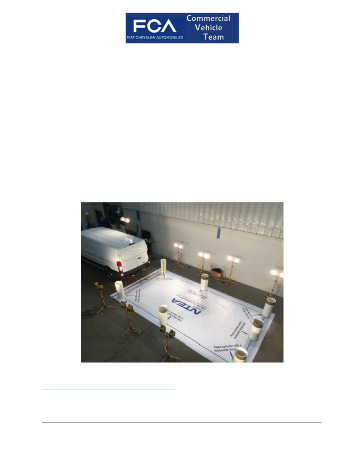
The NTEA has developed a test method and provided educational resources to help members understand FMVSS111
and verify that the system meets image size and field of view requirements. We recommend that you use the NTEA
method to determine an appropriate camera location and angles.
NTEA members can purchase the kit through the NTEA web site.
http://www.ntea.com/StoreCategory?Cat=PUBSGUIDES
See items titled FMVSS 111 FIELD OF VIEW (REARVIEW CAMERA) CONFORMITY MANUAL (# 2296) or FMVSS 111 FIELD
OF VIEW CONFORMITY MANUAL AND KIT. (# 2297)

ANALOG BACK UP CAMERA
FCA US LLC - Body Builder Instruction All Rights Reserved
1/15/2019 Page 4of 9
Camera Mounting
General
Unless the up fit has been designed with a feature to mount the camera, a bracket or a mounting feature on the up fit
will need to be developed. If practical, it is desirable to mount the camera in a location where the connector on the
rear of the camera can be inside the up fit and shielded from the outside environment. If fabricating a bracket, it should
be designed to offer as much protection to the camera and connector as possible. A mechanical layout of the camera
is in Appendix A.
Placement
ATTENTION: The camera placement zone shown below is intended to assist the
upfitter in meeting the requirements of FMVSS111. Compliance to
FMVSS111 will be the responsibility of the final stage manufacturer
who certifies the vehicle.
NOTE: This information is provided for directional purposes only, based on
testing performed by FCA US LLC.
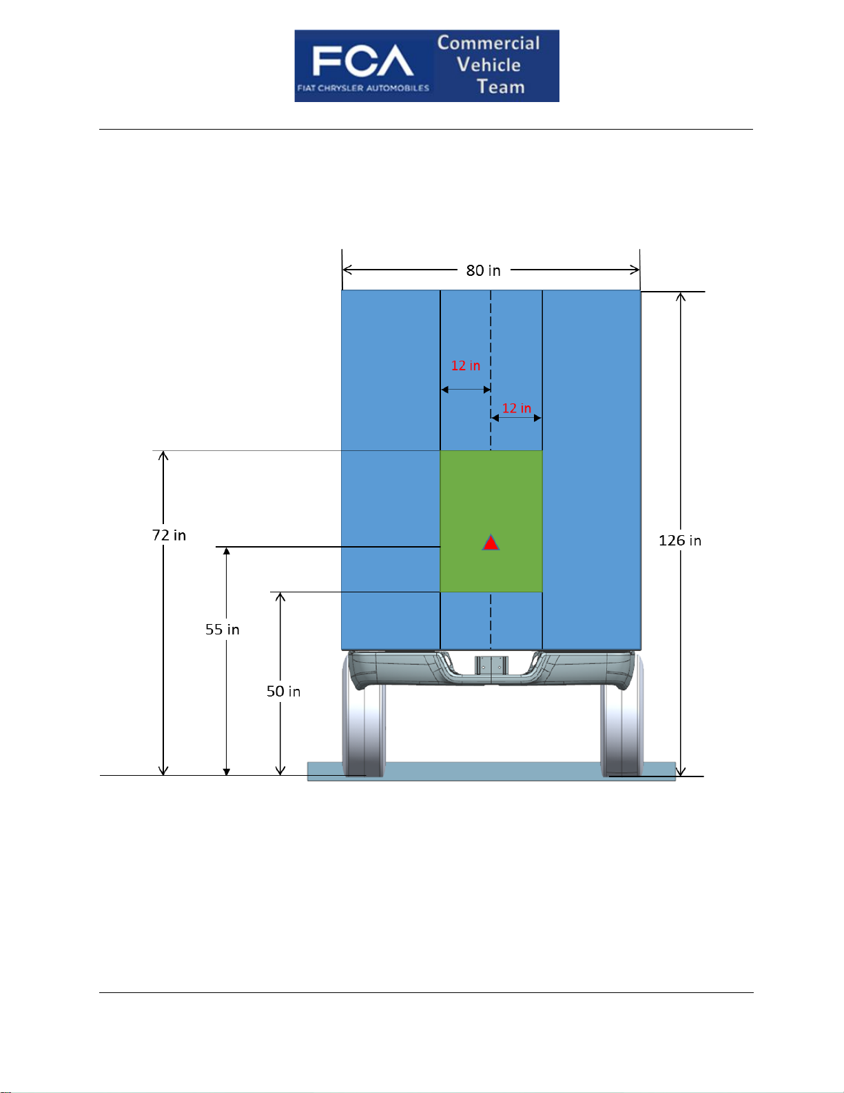
The recommended camera placement zones are defined in Figures 1 and 2. The diamond in the center of the green
zone is the optimum placement location. Lateral dimensions are from the centerline of the vehicle and vertical
dimensions are from the ground plain. Figure 1 is the recommended camera mounting location for the rear view mirror
display and Figure 2 is the recommended camera mounting location for the 5, 8.4 and 12 inch screens.
If the camera is mounted somewhere within the specified zone, the system is capable of meeting FMVSS111.
Depending upon the up fit, it may be possible to meet FMVSS111 with the camera mounted in areas outside of the
recommended zone. However gaining compliance may be difficult and may require more development work.

ANALOG BACK UP CAMERA
FCA US LLC - Body Builder Instruction All Rights Reserved
1/15/2019 Page 5of 9
Figure 1
CAMERA MOUNTING LOCATION WITH REAR VIEW MIRROR DISPLAY
ANALOG BACK UP CAMERA
FCA US LLC - Body Builder Instruction All Rights Reserved
1/15/2019 Page 6of 9
Figure 2
CAMERA MOUNTING LOCATION WITH 5, 8.4 or 12 INCH RADIO DISPLAY

ANALOG BACK UP CAMERA
FCA US LLC - Body Builder Instruction All Rights Reserved
1/15/2019 Page 7of 9
Aim
The camera should be mounted so the lateral (cross vehicle) centerline of the camera is parallel to the lateral (cross
vehicle) centerline of the vehicle. In other words, the camera aimed straight rearward, not left or right.
The vertical aim or “look down angle”will be selected to achieve FMVSS111 compliance.
Look Down Angle Determination
The NTEA FMVSS111 field of view conformity manual and kit (NTEA # 2297) should be used to determine the
appropriate look down angle to meet FMVSS111 field of view and image size requirements.
ATTENTION: When the vehicle is first placed in reverse, there will be a warning
message at the top of the screen for the first 5 seconds. THAT
WARNING MESSAGE CANNOT INTERFERE WITH THE TEST OBJECTS.
If it does, you may need to adjust the look down angle upward slightly
to compensate. Examples of images to demonstrating message
interference are in Appendix B Please note these are SIMULATED
images.

ANALOG BACK UP CAMERA
FCA US LLC - Body Builder Instruction All Rights Reserved
1/15/2019 Page 8of 9
Appendix A

ANALOG BACK UP CAMERA
FCA US LLC - Body Builder Instruction All Rights Reserved
1/15/2019 Page 9of 9
Appendix B
In the following image, the system does not meet FMVSS11 requirements with the warning message displayed. The
message covers the top of the rear cones and the black stripes are obscured.
In the following image, the system does meet FMVSS11 requirements with the warning message displayed. The
message is well above the top of the rear cones and the black stripes are completely visible.
This manual suits for next models
5
Table of contents
Other FCA US Car Video System manuals


Popular Car Video System manuals by other brands

Alpine
Alpine TME-M790 owner's manual

Pioneer
Pioneer Super Tuner III D AVH-P6550DVD installation manual

Alpine
Alpine iXE-W400E Software Update Instruction Manual

ASA Electronics
ASA Electronics Voyager VOM-783 Operation manual

Clarion
Clarion VRX93SVD owner's manual

NavAtlas
NavAtlas DXU1100DVR Installation & owner's manual

Sanyo
Sanyo NV-E7500 - Navigation System With DVD Player Service manual

Boss Audio Systems
Boss Audio Systems BV9968BI user manual

Kenwood
Kenwood DMX1037S instruction manual

Kenwood
Kenwood DDX630BT installation manual

Sony
Sony XAV-A1 - Av Center Installation/connections

FAAFTECH
FAAFTECH FT-LVDS-AUD4 installation manual


