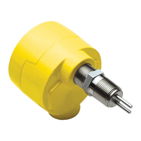
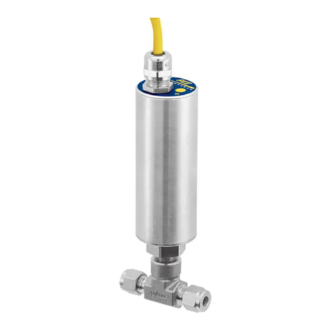
FCI FS10A Original operating instructions

Models FS10A, FS10i
Analyzer Flow Switch / Monitor
Fluid Components International LLC (FCI). All rights reserved.

06EN003394 Rev. K FS10 Series
Fluid Components International LLC
Notice of Proprietary Rights
This document contains confidential technical data, including trade secrets and proprietary information which is the property of Fluid Components International LLC (FCI).
Disclosure of this data to you is expressly conditioned upon your assent that its use is limited to use within your company only (and does not include manufacture or
processing uses). Any other use is strictly prohibited without the prior written consent of FCI.
© Copyright 2018 by Fluid Components International LLC. All rights reserved. FCI is a registered trademark of Fluid Components International LLC. Information subject to change without notice.

FS10 Series 06EN003394 Rev. K
Fluid Components International LLC iii
Table of Contents
TECHNICAL SPECIFICATIONS .....................................................................................................................................................................1
1 INSTRUMENT DESCRIPTION AND IDENTIFICATION .........................................................................................................................2
2 INSTRUMENT INSTALLATION ................................................................................................................................................................2
Special Conditions for Safe Use.......................................................................................................................................................................................2
Remote Flow Element Installation Into Zone 1, Division 1 Areas ...................................................................................................................................2
Mounting Orientation.......................................................................................................................................................................................................3
3 INSTRUMENT WIRING.............................................................................................................................................................................4
Recommended Minimum Wire Gauge ............................................................................................................................................................................4
Grounding .........................................................................................................................................................................................................................4
Input Power, 24 VDC.........................................................................................................................................................................................................4
FS10 Output Modes..........................................................................................................................................................................................................8
Switching Inductive Loads................................................................................................................................................................................................8
FS10 Outline Installation Drawing ...................................................................................................................................................................................9
FS10 1/4-Inch Tube Tee Assy With 1/8” Tube Adapters And Injection Tubes...............................................................................................................10
FS10 Flow Element Options............................................................................................................................................................................................11
FS10 Remote Enclosure and Connection Options..........................................................................................................................................................12
FS10i Top Assembly........................................................................................................................................................................................................13
Configuration Overview...............................................................................................................................................................................................13
Sensor Subassembly...................................................................................................................................................................................................14
Dimensional Outlines .....................................................................................................................................................................................................15
Installation Dimensions, FS10 Remote Panel Mounting Ring Kit (025719-01)..............................................................................................................17
Installation Dimensions, FS10 Remote Mounting Bracket (025442-01)........................................................................................................................18
Installation Details, FS10 Silicone Boot and UV Filter...................................................................................................................................................19
4 POWER UP, FUNCTIONAL VERIFICATION AND ADJUSTMENT ......................................................................................................21
5 SET-UP AND OPERATION ......................................................................................................................................................................21
FS10 Function Overview.................................................................................................................................................................................................21
FS10 Field Quick Setup Procedure..................................................................................................................................................................................22
Quick Setup Mode Summary..........................................................................................................................................................................................23
FS10 Button Controls – Alternate Setup Method..........................................................................................................................................................25
Normal Set-Up and Operation Using the Button Interface............................................................................................................................................26
Flow Switch Operation...................................................................................................................................................................................................26
Minimum Flow Setting (Function 6)............................................................................................................................................................................26
Maximum Flow Setting (Function 7) ...........................................................................................................................................................................26
Switch Point Adjust (Function 1 or 2)..........................................................................................................................................................................26
Additional Switch Settings.............................................................................................................................................................................................27
Fail-safe Position (Function 3).....................................................................................................................................................................................27
Hysteresis (Function 8 and 9)......................................................................................................................................................................................27
Time Delay (Function 10 or 11)....................................................................................................................................................................................27
Alarm Simulation (Function 12)...................................................................................................................................................................................27
Filter Setting (Function 14)..........................................................................................................................................................................................27
FS10 Recommended Point Level Interface Setup Procedure.........................................................................................................................................28

06EN003394 Rev. K FS10 Series
iv Fluid Components International LLC
Preferred Method: Level Can Be Adjusted During Setup ...........................................................................................................................................28
Probe Normally Wet, Level Cannot Be Adjusted During Setup..................................................................................................................................28
Probe Normally Dry, Level Cannot Be Adjusted During Setup ...................................................................................................................................28
Output and Display Parameters......................................................................................................................................................................................29
PC Interface and Command Line Interface Configurations ...........................................................................................................................................31
FS10 Communication Options.....................................................................................................................................................................................31
Windows PC Interface Software....................................................................................................................................................................................32
Flow Rate Indication on PC Interface..........................................................................................................................................................................32
Power Supply Interface Kit..........................................................................................................................................................................................32
Using the K Factors Calculation Window ..................................................................................................................................................................37
FS10 Serial Interface (Command Line, Alternate Communication Interface)................................................................................................................40
Password Protection....................................................................................................................................................................................................42
Command Line Interface Commands ..........................................................................................................................................................................42
6 SAFETY INSTRUMENTED SYSTEMS REQUIREMENTS (SIS)...........................................................................................................46
Compliance through FMEDA (Failure Modes, Effects and Diagnostic Analysis) .......................................................................................................46
FS10 Safety Identification...........................................................................................................................................................................................46
Installation in SIS Applications...................................................................................................................................................................................46
Product Repair.............................................................................................................................................................................................................46
FS10 SIS Reference.....................................................................................................................................................................................................46
7 MAINTENANCE AND TROUBLESHOOTING .......................................................................................................................................47
Maintenance ...............................................................................................................................................................................................................47
Troubleshooting...........................................................................................................................................................................................................47
APPENDIX A APPROVALS ........................................................................................................................................................................49
EC Declaration of Conformity......................................................................................................................................................................................49
SIL Declaration of Conformity.....................................................................................................................................................................................53
APPENDIX B AUXILIARY DRAWINGS ....................................................................................................................................................55
PC Interface Kits.............................................................................................................................................................................................................58
022083-02 Power Supply/Interface Box Kit...................................................................................................................................................................59
022083-01 Power Supply/Interface Box.........................................................................................................................................................................59
PC Interface Components...............................................................................................................................................................................................60
Board Connectors - OEM................................................................................................................................................................................................61
DB9 Connection Schematic............................................................................................................................................................................................62
Field Wireable Connector, M12, 8-Pin Male/Female, FS10...........................................................................................................................................63
APPENDIX C CUSTOMER SERVICE.........................................................................................................................................................65
Customer Service/Technical Support..........................................................................................................................................................................65
Warranty Repairs or Returns.......................................................................................................................................................................................65
Non-Warranty Repairs or Returns...............................................................................................................................................................................65
Extended Warranty......................................................................................................................................................................................................66
Return to Stock Equipment..........................................................................................................................................................................................66
Field Service Procedures.............................................................................................................................................................................................66
Field Service Rates......................................................................................................................................................................................................66

FS10 Series
Fluid Components International LLC 1
Instrument
Media Compatibility
All gases and liquids compatible with 316L stainless steel and Hastelloy C22.
Process Connection
FS10A: ¼" NPT; compatible with ¼", 3/8" and ½" tube tee,
¼" tube tee with 1/8" injection tube adapters and SP76 adapter (FCI
part number 019897-01)
FS10i: ½" male NPT compression fitting with 316 SST or Teflon ferrule
¼" male NPT 316 SST (2-inch [50 mm] fixed length)
Flow Sensitivity/Range
Air: 0.25 to 400 SFPS [0,076 to 0,15 MPS]
Water: 0.01 to 0.5 FPS [0,003 to 0,15 MPS]
Air/Gas Liquids
CC / Min SCFH CC / Min GPH
Min Max Min Max Min Max Min Max
1/8” tube adapter with
0.0625” ID injection tube 10 2,000 0.02 5 0.70 18.00 0.01 0.30
1/8” tube adapter with
0.0940” ID injection tube 25 5,000 0.05 10 1.50 40.00 0.03 0.60
1/4” tube tee 50 20,000 0.10 40 4.00 100.00 0.07 1.70
SP76 adapter 50 20,000 0.10 40 4.00 100.00 0.07 1.70
3/8” tube tee
180
50,000 0.40 100
14.00
350.00 0.20 5.50
1/2” tube tee
375
100,000 0.80 200
30.00
750.00 0.50 12.00
Repeatability
± 0.5% of reading
Temperature Coefficient
For temperatures > ±30 °F [±16 °C]
Gas: Maximum ±0.025% of reading/°F up to 500 °F
[±0.05% of reading/°C up to 260 °C]
Liquid: Maximum ±0.2% of reading/°F up to 250 °F
[±0.367% of reading/°C up to 121 °C]
Turndown Ratio: 5:1 to 100:1
Agency Approvals
Integral Electronics
FM, FMc: Nonincendive, Class I Division 2 Groups A, B, C, D;
Class II, Division 2 Groups E, F, G; Class III,
T4@Ta=71°C Type 4X
ATEX, IEC: Nonincendive for gas and dust, Zone 2
II 3 G Ex nA IIC T4 Gc, -40 °C ≤Ta ≤+71 °C
II 3 D Ex tc IIIC T 81°C Dc, -40 °C ≤Ta ≤+71 °C
IP64
Ingress Protection: IP65, IP66, IP67 in non-hazardous locations.
CE Marking, CRN, complies with Canadian Electrical code requirements of
ANSI/ISA 12.27.01-2011 as a single seal device.
IEC 61508 (SIL): SIL 2 compliant; Safe Failure Fraction (SFF) 90%
Remote Flow Element
FM, FMc: Class I, Division 1, Groups A, B, C, D; T2...T6
Ta = -40 °C TO +65 °C (Electronics)
Class II/III, Diviison 1 Groups E, F, G; T2...T6
Ta = -40 °C TO +65 °C (Electronics); Type 4x, IP67
Tp = -40 °C TO 260 °C (T1...T6) Includes Div1/Zone1 ambient
temperature zone.
ATEX: II 2 G Ex d IIC Gb T2....T6; Ta = 40 °C TO +65 °C
II 2 D Ex tb IIIC Db T300 °C...T85 °C; IP67
IEC: Ex d IIC Gb T2....T6; Ta = 40 °C TO +65 °C
Ex tb IIIC Db T300 °C...T85 °C; IP67
Refer to Probe Installation Operation manual [06EN003428] for
Zone 1/Division 1 installation.
Flow Element
Materials of Construction (wetted parts) 316L stainless steel with Hastelloy
C22 thermowells; optional, all Hastelloy C22 probe assembly
Operating Temperature
Standard: -40 °F to 250 °F [-40 °C to 121 °C]
FS10i, Teflon ferrule: -40 °F to 200 °F [-40 °C to 93 °C]
Electronics limited to 160 °F [71 °C]
Remote probe with polyurethane cable limited to 194 °F [90 °C]
Medium Temp: -40 °F to 500 °F [-40 °C to 260 °C]; remote configuration
only - probe and Teflon jacketed cable.
Operating Pressure
Tube tee and insertion: 2000 psig [138 bar(g)]
FS10i, Teflon ferrule: 150 psig [10 bar(g)]
SP76 adapter: Per SP76 manifold specifications up to 500 psig
[34 bar(g)] maximum
Remote flow element; IP67
Transmitter/Electronics
Enclosure
NEMA 4X [IP64], CE rated (Div 2, Zone 2 areas)
IP64, IP65, IP66, IP67 in non-hazardous locations
Operating Temperature
-40 °F to 160 °F [-40 °C to 71 °C]
Output Signals
Standard:
(1) Relay (SPDT, 1A @ 24 VDC); [1A @ 24 VDC/120 VAC, FM and FMc only]
or (1) Open Collector N-Channel MOSFET (100 mA);
(1) 4-20 mA* (500 Ωmax. load). User scalable, general purpose, uncali-
brated output proportional to flow rate for trend monitoring.
(1) RS232C Serial I/O
(For linearized, calibrated analog outputs see FCI thermal mass flow meter
products)
* Fault indication per NAMUR NE43 guidelines, user selectable high (>
21.0 mA) or low (< 3.6 mA)
Display
10 LED array, red; sequential lighting proportional to flow trend and flashes
at setpoint
User Interface
Two top-mounted push buttons to program switch point, zero and span set-
ting, relay hysteresis and time delay; button operation may be user disabled
to prevent unwanted changes; all set-up functions also programmable via
RS232C port
Input Power
24 VDC (21.5 VDC to 30 VDC); maximum 2.5 watts
Remote Configuration
Transmitter/electronics may be remote-mounted from flow element using
interconnecting cable; remote flow element available with
potted cable in 6’, 15’ or 30’ [2 m, 5 m or 10 m] length and M12 connection
plug at electronics; optional extended temperature service to 500 °F [260 °C]
with selection of PTFE jacketed cable.
TECHNICAL SPECIFICATIONS

FS10 Series
2 Fluid Components International LLC
2 INSTRUMENT INSTALLATION
The FS10 is marked with a flow direction arrow or “A” etched onto the sensor element. It is located on the flattened area of the sensor body
close to the housing or on the assembled tee. For 1/4 and 3/8 inch tube tees, mount the instrument with the “A” upstream of the flow to maximize sensi-
tivity at low flow rates (flow into the “A”). Larger line sizes should follow the flow arrow direction. Refer to Figure 1. Where the flow tube is not included
with the sensor assembly, the orientation mark must be parallel to flow (±3°). For liquid vertical flows in particular, FCI recommends the sensor ele-
ment be installed where flow is in the up direction. In vertical low flow gas applications, flow in the down direction is recommended.
As a level device, the orientation mark can be perpendicular or parallel to the liquid level. The sensor element may be installed top mount 90° to the
liquid surface. The sensor element can be at any angle as long as the flow direction follows the flow arrow. Liquid applications where the flow ele-
ment is positioned other than horizontally, FCI recommends the flow go in the up direction.
Caution:
To minimize the possibility of damage, leave the protective covers over the sensing area in place until the time of installation.
Take extra precaution with the sensing elements and surface when installing.
For NPT process connections: Apply the appropriate sealant compatible with the process media to the male threads. Tighten until the orientation
mark is positioned correctly. Check for leaks.
Note
: ATEX/IEC labeled units are supplied with a UV filter disc located inside the silicone boot. The disc can be removed if the
display is not subjected to UV light (e.g., sunlight, mercury-vapor lighting, etc.). See “Installation Details, FS10 Silicone Boot
and UV Filter” on page 19 for UV filter disc removal details.
Special Conditions for Safe Use
a. Provisions shall be made to prevent the rated voltage being exceeded by transient disturbances of more than 40%.
b. For applications in explosive atmospheres caused by air/dust mixtures, cable and conduit entries used shall provide a degree of ingress
protection of at least IP 54 according to EN 60529.
c. When the temperature under rated conditions exceeds 158 °F [70 °C] at the cable or conduit entry point, or 176 °F [80 °C] at the branching
point of the conductors, the temperature specification of the selected cable shall be in compliance with the actual measured temperature.
d. Cable gland assemblies are factory tightened – do not adjust; M12 connectors assembled finger-tight. Mencom MDC-8MR-PG9 or equal
M12 connector is used on FS10.
e. Parts of the enclosure are non-conducting and exceed the maximum permissible resistance according to IEC 60079-0. Therefore, to avoid
electrostatic charge build-up, it must not be rubbed or cleaned with solvents or a dry cloth when installed/used within a potentially
explosive atmosphere.
Remote Flow Element Installation Into Zone 1, Division 1 Areas
Refer to Probe Installation, Operation & Maintenance manual (06EN003428) for Zone 1/Division 1 installation.
1 INSTRUMENT DESCRIPTION AND IDENTIFICATION
The FS10 Series is a universal flow monitor and switch specifically designed for gas and liquid process analyzer sampling systems. The FS10A is a fast re-
sponding, highly repeatable sensor which installs easily into a standard tube tee fitting or SP76 (NeSSI) modular manifold. The FS10i is an insertion type
instrument with ¼-inch or ½-inch NPT fitting (fixed 2- or 4-inch length) or ½-inch NPT compression fitting (6-inch length, Teflon or stainless steel ferrule).
FLOW

FS10 Series
Fluid Components International LLC 3
Flow Direction Arrow
Sensors perpendicular
“A” (Active) mark
Upstream
Flow Direction
Sensors parallel
Left to Right Flow Example in 1/4 and 3/8 inch tube tees
For optimum sensitivity in low flow applications, install probes
with the “A” (Active) sensor positioned upstream.
Horizontal lines: gas or liquid.
Vertical lines: gas - flow must be down
liquid - flow must be up
FS10i
Install probe with reference flats parallel to flow and
arrow on top in horizontal installations.
Right to Left Flow Example in 1/2 inch or greater tube or
pipe tee
Probes mounted into 1/2 inch or greater tees are installed
with the sensors positioned perpendicular to the flow path in
the tee. Orient with the “A” (Active) facing up in side mount
horizontal configurations. These sensors may also be marked
with a flow direction arrow.
Mounting Orientation
Figure 1 – Mounting Orientation

FS10 Series
4 Fluid Components International LLC
3 INSTRUMENT WIRING
Only qualified personnel are to wire or test this instrument. The operator assumes all responsibilities for safe practices while wiring or troubleshoot-
ing. One of the following wiring instruction and diagrams illustrate the requirements for power input, alarm and analog outputs and safety instruc-
tions for the unit being installed.
Caution:
The instrument contains electrostatic discharge (ESD) sensitive devices. Use standard ESD precautions when handling the
instrument.
Recommended Minimum Wire Gauge
The following wire gauge chart specifies the correct wire for the distance to the power source or loads. Note that the open collector option is limited to
50 ft. It is also recommended that the open collector cable is shielded and that it is not run in the same conduit with the power source or the relay load.
Table 1 – I/O Wiring Gauge vs. Distance
Grounding
The switch must be properly connected to earth ground for safety and operational reasons.
The circuit board is tied to the enclosure case internally and both are tied to the probe assembly. If the installation pipe or vessel is not properly
grounded, connection to earth ground may be connected at the output connector, i.e. M12 or cable pigtail. Use the recommended wire gauge speci-
fied for the input power and distance listed in the chart above. Do not connect the earth ground to DC ground (terminals are marked “GND”,
"RTN", “COM” or “–”).
Input Power, 24 VDC
FCI recommends installing an input power disconnect and a fuse near the instrument to interrupt power during installation, maintenance, calibration,
alarm selection and troubleshooting procedures. Install conduit according to the local electrical codes or hazardous location requirements.
Attach the power leads according to the Input/Output connection schematic on the following page. If the unit has an M12 interface, verify that the
mating connector pin numbers match the designations of the wiring diagram. If the unit is supplied with a cable pigtail, connect the flying leads via
an approved terminal block or connector in an electrically safe and approved conduit box.
Attach the wires to the relay and other functions as needed. The relay contact conditions are shown in the alarm state (de-energized). The relay’s maxi-
mum rating is 1 A @ 24 VDC/120 VAC (FM only), 24 VDC (ATEX), resistive loads.
Refer to Section 5 for the setpoint and alarm state settings.
Connection Maximum Diameter (guage)
10’ 50’ 100’ 250’ 500’ 1000’
(3 m) (15 m) (30 m) (76 m) (152 m) (305 m)
Input Power (24 VDC nominal) 24 24 22 22 20 18
Relay Output (1 amp contacts) 18 16 14 12 10 X
Open Collector Output 24 22 X X X X
4-20 mA Output 24 24 22 22 20 18

FS10 Series
Fluid Components International LLC 5
Caution:
Instrument power is provided to Pin 1 of the I/O connector/cable (white wire). To avoid equipment damage always be sure
that power is connected to Pin 1 (white wire) when making external I/O cable connections. Do NOT apply power to Pin 8 (red
wire) or any other pin other than Pin 1.

FS10 Series
6 Fluid Components International LLC
FLOW ELEMENT WIRING DIAGRAM, FS10
REMOTE W/ 8-WIRE CABLE
BOARD ONLY (OEM)
021548-00
C01053-1-2
CABLE AND EARTH GND
ACT & REF DRIVE -
REF SENSE -
CABLE SHIELD
ACT
RTD
REF
RTD
REF SENSE +
REF DRIVE +
ACT SENSE +
ACT SENSE
-
ACT DRIVE +
8
4
7
6
5
2
3
1
1
1
2
3
4
3
2
4
(2) CONNECTORS
(FCI 021487-02
PIN NUMBER
J3 TERMINAL STRIP
SIGNAL NAME/PIN NUMBER
CUT JUMPERS
(J4 & J5)
8-WIRE SHIELDED
CABLE
(LOW/MED TEMP)
FLOW ELEMENT
WITH POTTED CABLE
CIRCUIT BOARD
8-WIRE CABLE
FROM FLOW ELEMENT
WHT
BRN
GRN
YEL
BLU
PNK
GRY
RED
REFERENCE ONLY
FLOW ELEMENT
WITH POTTED CABLE
RTD
REF
RTD
ACT
8-WIRE
WHT
BRN
2
1
GRN
YEL
BLU
PNK
GRY
3
4
6
7
5
FEMALE / MALE
CONN PAIR
M12, 8-PIN
FS10 ENCLOSURE
CABLE AND EARTH GND
ACT & REF DRIVE -
REF SENSE -
REF SENSE +
REF DRIVE +
ACT SENSE -
ACT SENSE +
2
7
6
1
3
5
4
AT ENCLOSURE
M12
8
FACE VIEW OF MALE
ON FLOW ELEMENT
8 SOCKET RECEPTACLE
RED
8
FLOW ELEMENT WIRING DIAGRAM
REMOTE 8-WIRE CABLE
M12 8-PIN CONNECTOR AT ENCLOSURE FS10
021549-01
FROM FLOW ELEMENT
CABLE SHIELD
CABLE
SHIELDED
8-WIRE CABLE
C01054-1-3

FS10 Series
Fluid Components International LLC 7
(OEM)

FS10 Series
8 Fluid Components International LLC
1A 120 VAC/24 VDC
JP5 = 2-3
RELAY CONTACT RATED CURRENT:
OUTPUT PULSE SOURCE OUTPUT PULSE SINK
OPEN COLLECTOR
OUTPUT RELAY (Default Setting)
2N7002
4.3K
S
OUTPUT ALARM
SETPOINT OUTPUT ALARM
SETPOINT
10K
10K
GDQ3
+24VDC
VCC
JP8 = IN JP8 = IN
JP5 = OUT
NOTE:
2N7002
S
GDQ3
CUSTOMER POWER SOURCE
AND LOAD NOT TO EXCEED
50 VDC and 40 mA.
2N7002
S
+24V
GDQ3
-+
COIL
K1
NO
NC
C
JP8 = OUT
JP5 = 1-2
FREQUENCY OUTPUT CORRESPONDING
TO FLOW WITH PULSE WIDTH AT 50%
DUTY CYCLE FOR RATES 1 TO 2000 Hz.
5.5 mA LOAD PULSED.
RECOMMENDED LOAD RESISTOR = 10 KΩ
ALARM FUNCTION (SETPOINT).
FREQUENCY OUTPUT CORRESPONDING
TO FLOW WITH PULSE WIDTH AT 50%
DUTY CYCLE FOR RATES 1 - 2000 Hz.
RECOMMENDED LOAD RESISTOR = 10 KΩ
ALARM FUNCTION (SETPOINT).
SW_OUTPUT
OR OUTPUT
FREQUENCY
SW_OUTPUT
H OR H
LLOR OUTPUT
FREQUENCY
H OR H
LL
OUTPUT ALARM SETPOINT
SW_OUTPUT
C01265-1-1
Switching Inductive Loads
If the FS10A/FS10i relay contacts are to be used to energize or de-energize an external relay, diode suppression must be used across the external
relay coil. Use the guidelines in the following example to select the proper diode.
A Tyco Electronics relay K10P-11D15-24 is used as a slave relay. The DC coil voltage is specified at 24 VDC and the specification indicates a coil
resistance of 650 Ω. The DC coil current is calculated by dividing the rated coil power by the rated voltage VDC or dividing the rated voltage VDC by
the coil resistance. In this case the current through the coil will be around 37 mA (24 ÷ 650). Refer to the K10P-11D15-24 data sheet.
It is recommended the diode reverse voltage (Vr) rating be twice or greater the voltage across the relay and the diode forward current (IF) rating be
greater than the relay current. Diodes 1N914 or 1N4148 meet these limits for this case.
FS10 Output Modes
A schematic view of the FS10 output modes and corresponding jumper settings are shown below.
Figure 2 – Output Modes and Jumper Settings

FS10 Series
Fluid Components International LLC 9
FS10 Outline Installation Drawing

FS10 Series
10 Fluid Components International LLC
OPTIONAL TEE REPLACEMENT FOR HAMLET TEE
AVAILABLE ON REQUEST.
4. PRESSURE RATING, PER MAX. ALLOWED FS10A.
INJECTION TUBE ID
01 = COMPLETE TEE ASSY, .094 I.D.
02 = COMPLETE TEE ASSY, .063 I.D.
11 = REDUCER SUB-ASSY ONLY, .094 I.D.
12 = REDUCER SUB-ASSY ONLY, .063 I.D.
94 = PAIR (2) OF REDUCER SUB-ASSY .094 I.D.
63 = PAIR (2) OF REDUCER SUB-ASSY .063 I.D.
CONFIGURATION:
021865-XX
3. MATERIAL: ALL MATERIALS 316 OR 316L STAINLESS STEEL.
2. UNLESS OTHERWISE SPECIFIED DIMENSIONS ARE
IN INCHES. DIMENSIONS IN SQUARE BRACKETS
ARE IN [MILLIMETERS].
1.
NOTES: UNLESS OTHERWISE SPECIFIED.
INTERPRET DIMENSIONING AND TOLERANCING IN
ACCORDANCE WITH ASME Y14.5 - 2009.
TIGHTEN BOTH REDUCER ASSEMBLIES INTO TEE
HAND TIGHT, PLUS 3/4 TURN.
INSERT INJECTION TUBE INTO TUBE REDUCER TO
BOTTOM. WELD AND DRESS AS NEEDED TO
MAINTAIN .25 DIAMETER.
-01, -02 CONFIG
A A
SECTION A-A
-02 CONFIG SHOWN
REDUCER SUB-ASSY
-11, -12 CONFIG
TIGHTEN 1/4"TUBE TEE
COMPRESSION NUT,
2X
(1/8" TUBE (OD)
COMPRESSION
FITTINGS), 2X
REDUCER
SUB-ASSY, 2X
BRANCH TEE, FEMALE,
FNPT, HAMLET
1/4 NPT
INJECTION TUBE
1/32
MD
TUBE REDUCER FITTING, COMPRESSION TUBE END
.094 DIA. INJECTOR, -01 ONLY
.063 DIA. INJECTOR, -02 ONLY
2X
(.50)
(FOR CUSTOMER
TUBE INSERTION LG.)
-01 = .094 I.D.
-02 = .063 I.D.
.25 DRESS WELD
FLUSH IF NECESSARY
INJECTION TUBE, -11 = .094 ID
INJECTION TUBE, -12 = .063 ID
C01438-1-1
FS10 1/4-Inch Tube Tee Assy With 1/8” Tube Adapters And Injection Tubes

FS10 Series
Fluid Components International LLC 11
INTEGRAL CONFIGURATION
WITH STANDARD FLOW ELEMENT INTEGRAL CONFIGURATION
WITH ADAPTABLE FLOW ELEMENTS
1/2" NPT
FM: 3022666 PLUS
500° RATED ELEMENT
FCI PN 020800
ALL-WELDED
1/2" NPT
WIRE
PIGTAIL
.81 SHOWN
SEE TABLE
FM: 3013994
FLOW SENSOR ASSEMBLY,
1/2, 1 AND 2 INCH SIZES WITH BUTT WELD,
SANITARY FLANGES OR MALE NPT PROCESS CONNECTIONS
3/4" NPT PROCESS CONNECTION
316L SST
FM: 3018600
PROBE ASSEMBLY
FLOW
U
FM: 3023468 PLUS
500° RATED ELEMENT
FCI PN 019348
PRESS-FIT
1/4" NPT
FM: 302346 PLUS
500° RATED ELEMENT8
FCI PN 021145
PRESS-FIT
1/2" NPT
FM: 302266 PLUS
500° RATED ELEMENT6
FCI PN 020000
ALL-WELDED
1/4" NPT
LENGTH VARIABLE
FM: 3035947
FCI PN 021146-XX
PROBE ASSEMBLY WITH PROTECTOR,
ALL-WELDED, 1000 OHM,
ST51/OEM
XLENGTH
0.65
0.46
TABLE OF AVAILABLE LENGTHS
ADAPTABLE FLOW ELEMENTS
(SPECIAL ORDER)
SWAGELOK FITTING
1/2" OR 3/4" NPT
NPT
SIZE
1/4"
1/2"
U
1.57
1.67
LENGTHS
AVAILABLE
0.81
0.60
1.34
1.34
U
1.90
2.00
2.13
2.13
U
2.64
2.74
WELDED
1/4" NPT 1/2" NPT
PRESS FIT
POTTED
CABLE
1/4" NPT
PRESS FIT
POTTED
CABLE
M12
CONNECTOR
C01036-2-1
A
.61
.95
3.96
.94
.60 U-LENGTH
Ø
1.50
Ø
1.50
Ø
1.13
Ø
1.69
BOOT
TAG
FLOW ELEMENT PORT,
1/2
"-14 NPT
OR 1/4"-18 NPT
FLOW
TRANSMITTER, FT
FLOW
ELEMENT, FE
ACTIVE
SENSOR
REF.
SENSOR
TAG
BOOT
POLYESTER
OVERLAY DECAL
BOOT REMOVED
FOR CLARITY
M12, MALE
8-PIN POLYESTER
OVERLAY DECAL
BOOT REMOVED
FOR CLARITY
M12, MALE
8-PIN
FS10 Flow Element Options

FS10 Series
12 Fluid Components International LLC
C01037-1-2
FLOW ELEMENT SHOWN
WITH TUBE TEE
FLOW ELEMENT,
M12 FEMALE, 8-POSITION
POWER/SIGNAL,
M12 MALE, 8-POSITION OR
OPTIONAL CABLE GLAND
PANEL MTG. RING BRACKET,
OPTIONAL (incl. in kit 025719-01)
RS-232 2.5 mm TRS (STEREO)
PHONE JACK (under hex plug)
Boot and hex plug removed
to show RS-232 connection
FLOW ELEMENT OPTIONS
(SEE PRECEDING PAGE)
5.44
1.25
Ø
1.69, BOOT
Ø2.25
, OD
Ø
1.50, ENCLOSURE
(NO BOOT)
FS10 Remote Enclosure and Connection Options

FS10 Series
Fluid Components International LLC 13
U-Length = 2.00
[51]
U-Length = 2.00
[51]
U-Length = 6.00 max.
[152 max.]
CONFIGURATION:
FS10i-B10X
CONFIGURATION:
FS10i-E20X (Teflon Ferrule)
or
FS10i-F20X (Metal Ferrule)
CONFIGURATION:
FS10i-B20X C01360-1-1
FS10i Top Assembly
Note:
An FS10i housing is secured with removable screws. The original FS10A housing was secured with fixed pins that were not
removable in the field. Later versions of the FS10A are supplied with removable housing screws. The disassembly instruc-
tions below apply to any FS10 unit with removable housing screws.
Configuration Overview

FS10 Series
14 Fluid Components International LLC
Remove screws to reclock
probe orientation 90° or 180°.
Apply Loctite Blue to screw
threads before reinstalling.
CAUTION: Unit is supplied with
sufficient wire slack to rotate probe
180° in a single rotation for initial
set up. Do not over-rotate.
Remove only to
change jumper
selection on board
per diagram.
BOOT REMOVED FOR
CLARITY
C01342-1-1
Sensor Subassembly

FS10 Series
Fluid Components International LLC 15
Dimensional Outlines

FS10 Series
16 Fluid Components International LLC
Other manuals for FS10A
2
This manual suits for next models
1
Table of contents
Other FCI Switch manuals
Popular Switch manuals by other brands
TRENDnet
TRENDnet TE100-DX4PCI user guide

Cypress
Cypress CE66058 manual

pumpa
pumpa PC-18 Translation of the original instruction manual

HP
HP 316095-B21 - StorageWorks Edge Switch 2/24 user guide
Ross
Ross Synergy Q Engineering manual

Outback Power Systems
Outback Power Systems FLEXware FW-IOB-T-120/208VAC installation instructions
Tripp Lite
Tripp Lite NetController B042-004 Specifications

Vivo Link
Vivo Link VLHUB121-MME user manual
FOR-A
FOR-A VSF-6496 Operation manual
Ruby Tech
Ruby Tech FGS-2924R Specifications
3One data
3One data ICS5400TSN-24GT16GS4XS-LN Series Quick installation guide
High Sec Labs
High Sec Labs SM20N-3 user manual
