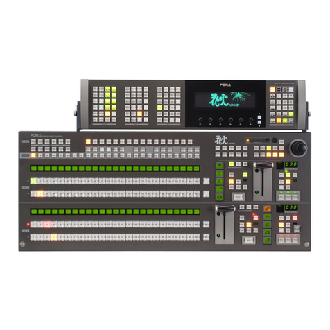
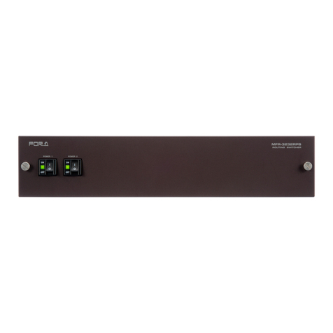
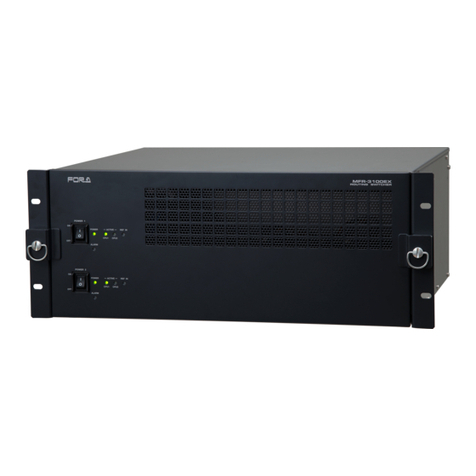
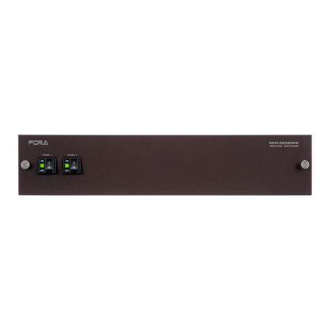
FOR-A VSF-6496 User manual

VSF-600 SERIES
Routing Switcher
*S
VSF-6496, VSF-64128
VSF-9632, VSF-9664
VSF-9696, VSF-96128
VSF-12832, VSF-12864
VSF-12896, VSF-128128
S/N 9310012 - Higher
1st Edition
OPERATION
MANUAL


Precautions
Important Safety Warnings
[Power]
Operate unit only on the specified supply voltage.
Disconnect power cord by connector only. Do not pull on cable portion.
Do not place or drop heavy or sharp-edged objects on power cord. A damaged cord
can cause fire or electrical shock hazards. Regularly check power cord for
excessive wear or damage to avoid possible fire / electrical hazards.
[Grounding]
Ensure unit is properly grounded at all times to prevent electrical shock hazard.
Do not ground the unit to gas lines, units, or fixtures of an explosive or dangerous
nature.
Ensure power cord is firmly plugged into AC outlet.
[Operation]
Do not operate unit in hazardous or potentially explosive atmospheres. Doing so
could result in fire, explosion, or other dangerous results.
Do not allow liquids, metal pieces, or other foreign materials to enter the unit. Doing
so could result in fire, other hazards, or unit malfunction.
If foreign material does enter the unit, turn power off and disconnect power cord
immediately. Remove material and contact authorized service representative if
damage has occurred.
[Transportation]
Handle with care to avoid shocks in transit. Shocks may cause malfunction. When
you need to transport the unit, use the original packing materials or alternate
adequate packing.
Stop
Caution
Hazard
Hazard
Caution
Hazard
Caution
Caution

[Circuitry Access]
Do not remove covers, panels, casing, or access circuitry with power applied to the
unit! Turn power off and disconnect power cord prior to removal. Internal servicing /
adjustment of unit should only be performed by qualified personnel.
Do not touch any parts / circuitry with a high heat factor.
Capacitors can retain enough electric charge to cause mild to serious shock, even
after power is disconnected. Capacitors associated with the power supply are
especially hazardous. Avoid contact with any capacitors.
Unit should not be operated or stored with cover, panels, and / or casing removed.
Operating unit with circuitry exposed could result in electric shock / fire hazards or
unit malfunction.
[Potential Hazards]
If abnormal smells or noises are noticed coming from the unit, turn power off
immediately and disconnect power cord to avoid potentially hazardous conditions. If
problems similar to above occur, contact authorized service representative before
attempting to again operate unit.
[Consumables]
The consumables used in unit must be replaced periodically. For further details on
which parts are consumables and when they should be replaced, refer to the
specifications at the end of the Operation Manual. Since the service life of the
consumables varies greatly depending on the environment in which they are used,
they should be replaced at an early date. For details on replacing the consumables,
contact your dealer.
[Rubber Feet]
If this product has come with rubber feet attached by screws, do not insert the
screws again without rubber feet after removing the rubber feet and screws. It may
cause damage to the internal circuits or components of the unit. To install the rubber
feet again to the unit, do not use other than the supplied rubber feet and screws.
Caution
Caution
Hazard
Stop
Caution

Upon Receipt
Unpacking
VSF-600 units and their accessories are fully inspected and adjusted prior to shipment.
Operation can be performed immediately upon completing all required connections and
operational settings.
Check your received items against the packing lists below.
ITEM QTY REMARKS
VSF-600 1
AC Cord 1
Rack Mount Brackets 1 set EIA standard type
Operation Manual 1 This manual
RS-232C Control Software 1 CD-ROM (for Windows)
Routing Switcher RS/VSF
Series Control Software 1 Separate manual
Check
Check to ensure no damage has occurred during shipment. If damage has occurred, or items
are missing, inform your supplier immediately.

Check Installed Board
Combination of installed boards on VSF-600 varies by the customer's requirement. Please
check that correct boards are installed as specified in the configuration table. Checking
procedure is shown below;
Checking procedure
1) Remove the two screws on the front panel of VSF-600.
2) The slot numbers are as below and the numbers are also labeled on the slots.
Slot 12
Slot 11
Slot 10
Slot 9
Slot 8
Slot 7
Slot 6
Slot 5
Slot 4
Slot 3
Slot 2
Slot 1
ON
OFF

Configuration Table
Model No Numbers of
Inputs/Outputs Numbers of
VSF-I3204 Numbers of
VSF-X6432 Slots for Installation
VSF-6496 64 Inputs x
96 Outrputs 2 3 1, 2, 3, 5, 7
VSF-64128 64 Inputs x
128 Outrputs 2 4 1, 2, 3, 5, 7, 9
VSF-9632 96 Inputs x
32 Outrputs 3 2 1, 2, 3, 4, 11
VSF-9664 96 Inputs x
64 Outrputs 3 4 1, 2, 3, 4, 5, 6, 11
VSF-9696 96 Inputs x
96 Outrputs 3 6
1, 2, 3, 4, 5, 6, 7, 8,
11
VSF-96128 96 Inputs x
128 Outrputs 3 8
1, 2, 3, 4, 5, 6, 7, 8,
9, 10, 11
VSF-12832 128 Inputs x
32 Outrputs 4 2 1, 2, 3, 4, 11, 12
VSF-12864 128 Inputs x
64 Outrputs 4 4 1, 2, 3, 4, 5, 6, 11, 12
VSF-12896 128 Inputs x
96 Outrputs 4 6
1, 2, 3, 4, 5, 6, 7, 8,
11, 12
VSF-128128 128 Inputs x
128 Outrputs 4 8
1, 2, 3, 4, 5, 6, 7, 8,
9, 10, 11, 12
3) After assuring boards are installed in correct slots, attach and secure the front panel with the
two screws.


Table of Contents
1. Prior to Starting ...........................................................................................................................1
1-1. About VSF-600 ...................................................................................................................1
1-2. Features..............................................................................................................................1
1-3. About This Manual ..............................................................................................................2
2. Part Descriptions.........................................................................................................................3
2-1. Front Panel .........................................................................................................................3
2-2. Interior Front Panel .............................................................................................................4
2-3. Rear Panel..........................................................................................................................6
3. Connection..................................................................................................................................7
3-1. Video Input/Output and external sync signal Connections..................................................7
3-2. Connections with Remote Control Unit ...............................................................................8
3-3. Connections with TG-1616 Title Generator.........................................................................9
3-4. Computer Control Connection ..........................................................................................10
3-5. Alarm Connector Connection ............................................................................................11
3-5-1. ALARM OUT Connector............................................................................................11
3-5-2. Connection Procedure ..............................................................................................12
3-5-3. Alarm Output Circuit Connection Example................................................................12
4. Internal Settings........................................................................................................................13
4-1. Video Input Card (VSF-I3204)...........................................................................................14
4-2. Video Crosspoint Card (VSF-X6432) ................................................................................15
4-3. CPU Card .........................................................................................................................16
4-3-1. Removing CPU Card ................................................................................................16
4-3-2. Dip switch / Jumper Settings.....................................................................................17
4-3-3. Setting the RS-232C/RS-422 Connector ..................................................................18
5. Applying Power .........................................................................................................................18
6. Parameter Settings ...................................................................................................................19
6-1. Setting Procedure .............................................................................................................19
6-2. Setting Items and Display .................................................................................................22
6-2-1. Version Display – ADR 00000000 – ..........................................................................22
6-2-2. RS-232C/RS-422 Baud Rate Setting – ADR 00010000 –.......................................23
6-2-3. Linkage Function Setting with TG-1616 – ADR 00010111 – ....................................23
6-2-4. Initialization Setting – ADR 11111111 –......................................................................24
7. Remote Control Connection......................................................................................................25
7-1. SERIAL I/F connector .......................................................................................................25
7-2. Cable connection example................................................................................................25

7-3. Remote Control via RU-3000 ........................................................................................... 27
7-4. VSF/TG Linkage............................................................................................................... 28
8. Serial Control............................................................................................................................ 31
8-1. General description .......................................................................................................... 31
8-2. RS-232C/RS-422 connector............................................................................................. 31
8-2-1. RS-232C Interface.................................................................................................... 32
8-2-2. RS-422 Interface ...................................................................................................... 33
8-3. Communication Parameters............................................................................................. 34
8-4. Protocol ............................................................................................................................ 34
8-5. Command Logic ............................................................................................................... 35
8-6. Operational Flow .............................................................................................................. 36
8-7. Control Commands .......................................................................................................... 37
8-7-1. Crosspoint Switching Commands............................................................................. 37
8-7-2. Preset Switching Commands ................................................................................... 38
8-7-3. Status Request Commands...................................................................................... 39
8-7-4. Response Commands.............................................................................................. 40
8-7-5. Control Commands and ASCII Codes ...................................................................... 42
9. Control by RS Commands........................................................................................................ 45
9-1. RS Command Format ...................................................................................................... 46
9-2. Salvo Function.................................................................................................................. 48
9-2-1. Clearing the Salvo Preset Table ............................................................................... 49
9-2-2. Recording the Salvo Crosspoints ............................................................................. 49
9-2-3. Clearing the Salvo Crosspoints ................................................................................ 50
9-2-4. Salvo Registration .................................................................................................... 50
9-2-5. Salvo Calling ............................................................................................................51
9-2-6. Checking the Salvo Registered Settings .................................................................. 52
9-3. Sequence Switching.........................................................................................................53
9-3-1. Sequence Switching Registration............................................................................. 53
9-3-2. Starting the Sequence Switching.............................................................................. 54
9-3-3. Stopping Sequence Switching.................................................................................. 55
9-3-4. Confirming Sequence Switching............................................................................... 55
9-4. Auto Salvo Switching........................................................................................................ 56
9-4-1. Auto Salvo Switching Registration............................................................................ 56
9-4-2. Starting Auto Salvo Switching................................................................................... 57
9-4-3. Stopping Auto Salvo Switching................................................................................. 57
9-4-4. Confirming Auto Salvo Switching.............................................................................. 58
9-5. Chop Switching ................................................................................................................ 59
9-5-1. Chop Switching Registration .................................................................................... 59
9-5-2. Starting Chop Switching ........................................................................................... 60
9-5-3. Stopping Chop Switching ......................................................................................... 61
9-5-4. Confirming Chop Switching ...................................................................................... 61
9-6. Alarm Switching................................................................................................................ 62

9-6-1. Alarm Switching Setting and Cancellation.................................................................62
9-6-2. Confirming Alarm Switching ......................................................................................62
9-7. Crosspoint Inhibit ..............................................................................................................63
9-7-1. Crosspoint Inhibit Setting..........................................................................................63
9-7-2. Canceling Crosspoint Inhibits....................................................................................64
9-7-3. Confirming Crosspoint Inhibit Setting........................................................................64
9-8. Destination Lock Function.................................................................................................65
9-8-1. Destination Lock Setting ...........................................................................................65
9-8-2. Confirming Destination Lock Setting.........................................................................66
9-9. Logical Channel Assignment.............................................................................................66
9-9-1. Logical Output Channel Assignment.........................................................................67
9-9-2. Confirming Logical Output Channel Assignment.......................................................70
9-9-3. Logical Input Channel Assignment............................................................................71
9-9-4. Confirming Logical Input Channel Assignment .........................................................72
9-10. Time................................................................................................................................73
9-10-1. Time Settings ..........................................................................................................73
9-10-2. Checking Time ........................................................................................................74
10. Optional Installation and Expansion........................................................................................75
10-1. Power Unit(VSF-600PS)............................................................................................75
10-1-1. Parts Descriptions...................................................................................................75
10-1-2. Installing Option Power Unit....................................................................................75
10-2. CPU Card(VSF-600CPU)...........................................................................................78
10-2-1. Settings and Checks...............................................................................................78
10-2-2. Installing Option CPU Card.....................................................................................80
10-3. Video Input Card (VSF-I3204).........................................................................................81
10-3-1. Settings and Checks...............................................................................................81
10-3-2. Adding Video Input Cards .......................................................................................82
10-4. Video Crosspoint Card (VSF-X6432) ..............................................................................84
10-4-1. Setting and Checks.................................................................................................84
10-4-2. Installing Option Video Crosspoint Card .................................................................85
11. If Problem Occurs ...................................................................................................................88
12. Specifications & Dimensions...................................................................................................89
12-1. Unit Specifications...........................................................................................................89
12-2. External Dimensions.......................................................................................................91


1
1. Prior to Starting
Congratulations! By purchasing VSF-600 routing switcher you have entered the world of FOR-A
and its many innovative products. Thank you for your patronage and we hope you will turn to
FOR-A products again and again to satisfy your video and audio needs.
FOR-A provides a wide range of products, from basic support units to complex system
controllers, which have been increasingly joined by products for computer video based systems.
Whatever your needs, talk to your FOR-A representative. We will do our best to be of continuing
service to you.
1-1. About VSF-600
The VSF-600 is a low-cost routing system with high performance and advanced functions that is
ideal for monitoring and audio-visual systems.
Control is possible over an RS-232C/RS-422 interface by a serial control device such as a
computer or by a remote control unit such as the RU-3000. The VSF-600 incorporates the
following internal cards and units for providing support for configurations from a minimum of 64
inputsx96 outputs or 96 inputsx32 outputs to a maximum of 128 inputs×128 outputs in
32-input×32-output units.
VSF-I3204:Video Input Card
Video input card for 32 video inputs. This Optional card can be added for
enabling expansion in 32-input units up to a maximum of 128 inputs.
VSF-X6432:Video Crosspoint Card
Video crosspoint card for 32 video outputs. Optional cards can be added
for enabling expansion in 32-output units up to a maximum of 128
outputs.
VSF-600PS:Power Supply
An optional power supply. Can be added for enabling redundant power
supply.
VSF-600CPU:CPU Card
An optional CPU board. Can be added for enabling redundant power
supply.
1-2. Features
6U-size frame with the capacity of 128×128 matrix
Configurations ranging from a minimum of 64×96 or 96×32 up to a maximum of 128×128 in
32-input×32-output units
Maintenance-friendly design
Easy front access to the boards and power units.
Easy back access to the fan motor.
Redundancy of the power supply and CPU card is possible for enabling safer system
operation (option)
Incorporates an RS-232C/RS-422 9-pin serial interface for enabling a wide array of
operations

2
Various crosspoint switching operations are available.
Standard crosspoint switching (Crosspoint switching)
Simultaneous switching of multiple crosspoints (Multiple switching)
Simultaneous switching of registered multiple crosspoints (Multiple registered switching)
Automatic switching of input channels at a selected time (Sequence switching)
Automatic switching of registered crosspoints (Auto salvo switching)
Alternate switching between two input channels (Chop switching)
Automatic switching to selected input channel when input signal is disconnected (Alarm
switching)
Alarm function can detect voltage drops in the power supply, stopping of the fan motor, and
malfunctions in the CPU card and indicate alarms by alarm signal output and the LEDs on the
front panel
Includes an operation, alarm, and communication log (record) function (to enable tracing of
causes when a malfunction occurs)
Up to 14 RU-3000 remote control units can be connected.
Enables connection of the FOR-A TG-1616 title generator for allowing camera title switching
linked to VSF crosspoints (VSF/TG linkage operation)
1-3. About This Manual
This manual is intended to help the user easily operate the VSF-600 and make full use of its
functions during operations. Before connecting or operating your unit, read this operation
manual thoroughly to ensure you understand the product. After reading, it is important to keep
this manual in a safe place and available for reference.
Font Conventions
The following conventions are used through out this manual:
Circled text (for example MATT) is used for buttons.
Shaded text (such as OFF) is used for the setting parameters and values in the menus.

3
(1) (1)
(2)(3)
(5) (4) (6)
2. Part Descriptions
2-1. Front Panel
(1) Screws Remove these screws to open front panel. (two screws)
(2) Power indicator (POWER 1) Power indication will be lit green whenever power switch
is set to ON and power applied to the unit.
(3) Power switch (POWER 1) Power switch. Used to turn unit power ON / OFF.
(4) ALARM-A Alarm function to detect failure of power ( POWER 1, 2 ),
fan or CPU card (CPU 1, 2 ), output alarm signal and lit a
LED on front panel
Normal condition: lit green
Detected error: lit red (Alarm signal)
Not installed: Lights off.
(5) Expansion POWER switch
( POWER 2 ) Used for the added optional power unit (VSF-600PS).
(6) ALARM-B Used for the added optional CPU card (VSF-600CPU).
Detects failure of power, fan or CPU card, output alarm
signal and lit a LED on front panel
* POWER 2 or CPU 2 indication will be displayed at the addition of the power unit or the
CPU card.

4
2-2. Interior Front Panel
Slots for Video input card, Video crosspoint card (Slot 1-12)
Slot 1 Video input card (VSF-I3204) Inputs1-32ch
Slot 2 Video input card (VSF-I3204) Inputs33-64ch
Slot 3 Video crosspoint card (VSF-X6432) Outrputs1-32ch (Inputs1-64ch)
Slot 4 Video crosspoint card (VSF-X6432) Outrputs1-32ch (Inputs65-128ch)
Slot 5 Video crosspoint card (VSF-X6432) Outrputs33-64ch (Inputs1-64ch)
Slot 6 Video crosspoint card (VSF-X6432) Outrputs33-64ch (Inputs65-128ch)
Slot 7 Video crosspoint card (VSF-X6432) Outrputs65-96ch (Inputs1-64ch)
Slot 8 Video crosspoint card (VSF-X6432) Outrputs65-96ch (Inputs65-128ch)
Slot 9 Video crosspoint card (VSF-X6432) Outrputs97-128ch (Inputs1-64ch)
Slot 10 Video crosspoint card (VSF-X6432) Outrputs97-128ch (Inputs65-128ch)
Slot 11 Video input card (VSF-I3204) Inputs65-96ch
(1)
Slot 12 Video input card (VSF-I3204) Inputs97-128ch
Slot for CPU card (Slot 13-14)
Slot 13 Standard CPU card(CPU 1)
(2)
Slot 14 Additional option CPU card (CPU 2: VSF-600CPU) See section 10-2. "CPU
Card(VSF-600CPU)" for installation.
ON
OFF (1)-2
(1)-3
(1)-4
(1)-5
(1)-6
(1)-7
(1)-8
(1)-9
(1)-10
(1)-11
(1)-12
(3)-15
(3)-16
(3)Scre
w
(3)Scre
w
(4) (2)-13 (2)-14
(1)Fixing plate
screw
(1)Fixing plate
screw
(5) (6)
(1)-1

5
Slot for power unit (Slot 15-16)
Slot 15 Standard power unit (POWER 1)
(3)
Slot 16 Additional option power unit (POWER 2: VSF-600PS)
(4) Unused Slot (Slot 17-18)
(5) Channel display card
Card to display status of crosspoints and each setting. In crosspoint mode, green
indication on the left shows input channels and red indication on the right shows output
channels.
(6) Additional channel display card
Card to display status of crosspoints and each setting. Used when the optional CPU card
(CPU 2: VSF-600CPU) is installed.
IMPORTANT
Video input cards and video crosspoint cars installed in slots are secured with two
fixing panel. (Each panel is secured with two screws.) Refer to section 10-3. "Video
Input Card (VSF-I3204)" and 10-4. "Video Crosspoint Card (VSF-X6432)". Each
power unit is secured with 3 screws, 2 in front and 1 in back. Each channel display
card is secured with 2 screws in front.

6
2-3. Rear Panel
(1) VIDEO IN Connector for video signal input. 75Ωterminated.
(2) VIDEO OUT Connector for video signal output.
(3) REF IN Connector for external reference signal input. Used to input external
standard black burst signal or composite sync signal. Switching is
performed by the reference signal input. If no cable is connected, the
REF IN connector is terminated at 75Ω.
(4) REF OUT Connector for external reference signal output. Used to output
Loopthru of externally input black burst or composite sync signal. (By
applying a cable to REF OUT, 75Ωtermination of REF IN is turned
OFF.) It would not output signal without CPU card.
(5) RS-232C/422 Used for RS-232C or RS-422 protocol control connection when
controlling crosspoint selection via computer. Connector is 9-pin
D-sub, male. Note that connector lock screws must be inch type
screws. (Factory default is RS-232C. See section 4-3-3. "Setting the
RS-232C/RS-422 Connector" for the setting details.)
(6) SERIAL I/F A/B
Used for control connection to optional remote control units
(RU-3000) or title generator (TG-1616). Connector is 9-pin D-sub,
female. Note that connector lock screws must be inch type screws.
(7) ALARM OUT Connector for alarm outputs. Detects failure of power, fan or CPU
card, and output alarm signal. (See section 3-5. "Alarm Connector
Connection" for the details.
(8) Ground
terminal Used to ground unit to protect operators against static electricity and
electrical shock.
(9) AC IN Used for connection to AC power source via supplied accessory cord.
Each power unit is secured with 3 screws, 2 in front and 1 in back.
(10) FAN Cooling fan unit. This fan unit is secured with 4 screws.
(11) Power unit
Blank panel Additional power unit (VSF-600PS). (See section 10-1 "Power Unit
(VSF-600PS)" for the installation.)
(12) NETWORK 1, 2 Unused
(10)
(5)
(6)
(3)
(4)
(9)
(8)
(1)
(2)
(1)
(7)
(11)
(12)

7
3. Connection
3-1. Video Input/Output and external sync signal
Connections
Video input and output connections should be generally made as below.
Display image as crosspoint settings.
(Input signals from cameras.)
Monitor 1
Camera 1 Camera 2 Camera 128
~
Monitor 2 Monitor128
~
External sync signal
(Black burst or composite
reference signal)
Loopthru from REF IN
VSF-600

8
3-2. Connections with Remote Control Unit
Crosspoint switching and other operations can be performed by remote control by connecting a
RU-3000 or RU-1616 remote control unit to the serial interface (I/F) of the VSF-600. See section
7-3. "Remote Control via RU-3000" for the details.
9 pin D-sub
terminator
9 pin serial cable
RU-3000 unit 1
REMOTE 2
REMOTE 1
9 pin D-sub
terminator
9 pin serial cable
RU-3000 unit 2
REMOTE 2
REMOTE 1
VSF-600
This manual suits for next models
10
Table of contents
Other FOR-A Switch manuals

FOR-A
FOR-A HVS-3800HS Quick setup guide

FOR-A
FOR-A MFR-3232 User manual

FOR-A
FOR-A HVS-300HS User manual

FOR-A
FOR-A MFR-4000R User manual

FOR-A
FOR-A HVS-190S User manual

FOR-A
FOR-A HVS-6000 User manual

FOR-A
FOR-A VSF-1616 User manual

FOR-A
FOR-A HVS-1000HS User manual

FOR-A
FOR-A HVS-492OU User manual

FOR-A
FOR-A RS-HD808 User manual

FOR-A
FOR-A MFR Series User manual

FOR-A
FOR-A MFR-6000R User manual

FOR-A
FOR-A Multi Viewer MV-40F(A) User manual

FOR-A
FOR-A MFR-6100 User manual

FOR-A
FOR-A VPS-700 MU User manual

FOR-A
FOR-A MFR-1616 User manual

FOR-A
FOR-A HVS-490 User manual

FOR-A
FOR-A MFR-3000 User manual

FOR-A
FOR-A HVS-350HS User manual

FOR-A
FOR-A HVS-490 User manual