0
LT4936 (1:01/08)
ENIGMA II SLIDE Maintenance Instructions
SECT ON TEN Maintenance nstructions
GENERAL
ervicing should be carried out annually by a competent person such as a CORGI-registered
person in accordance with the current Gas afety (Installation and Use) Regulations 1998 (as
amended), this should ensure the safe and correct operation of the appliance.
Before commencing any service or replacement of parts, turn off the gas supply to the fire.
After servicing check for gas soundness.
When ordering spare parts please quote appliance name and serial number, these can be
found on the data badge, which is located by removing the decorative fire trim.
At least once a year, check for debris in the catchment area behind the fire and in the flue way.
If soot has accumulated check, to establish cause, rectify and clean flue or chimney
accordingly.
FUEL BED CLEAN NG
mportant: - Refer to the ‘Health & Safety Notice located on page 3 of this
booklet before cleaning or replacing any refractory material.
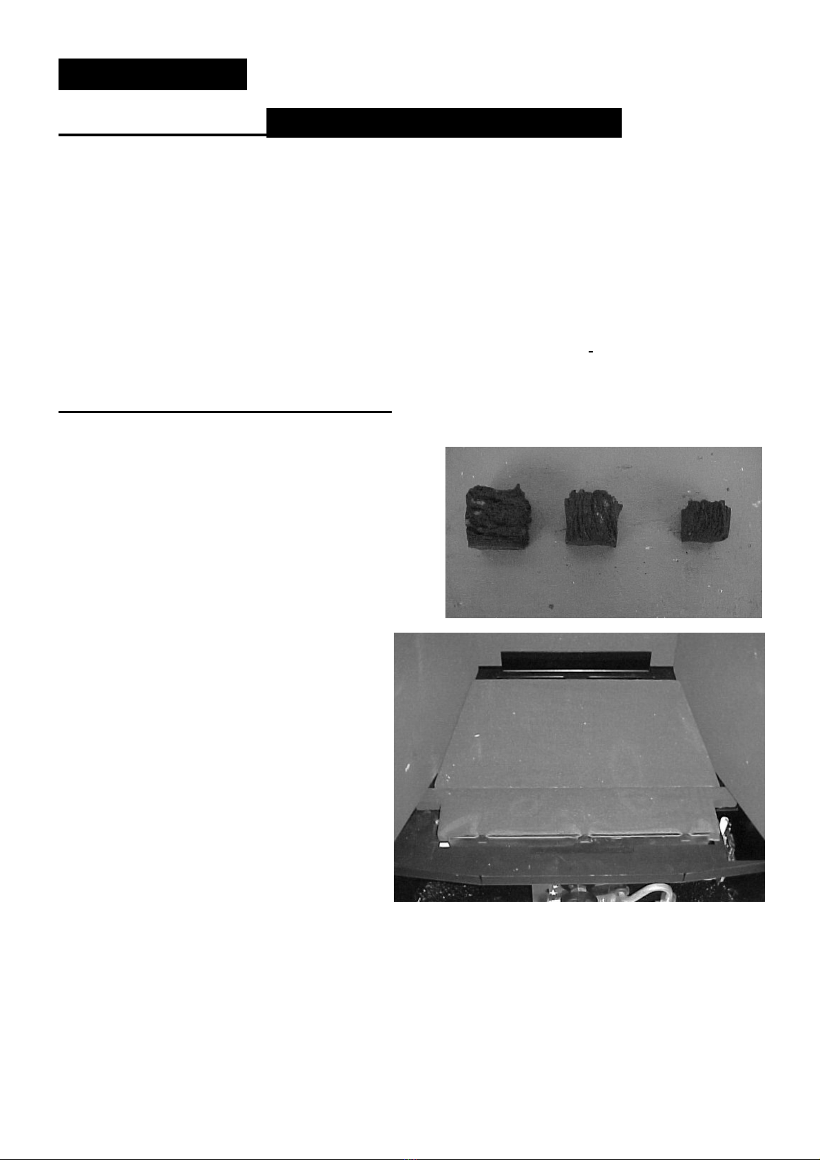
The fuel bed components are delicate and they should be handled with great care.
The loose parts and moulded shapes may be removed for cleaning. They can be brushed very
gently with a soft brush to remove dust or any deposits. A vacuum cleaner may only be used
after the loose components have been removed.
Examine the fuel bed components for signs of cracking and replace if necessary.
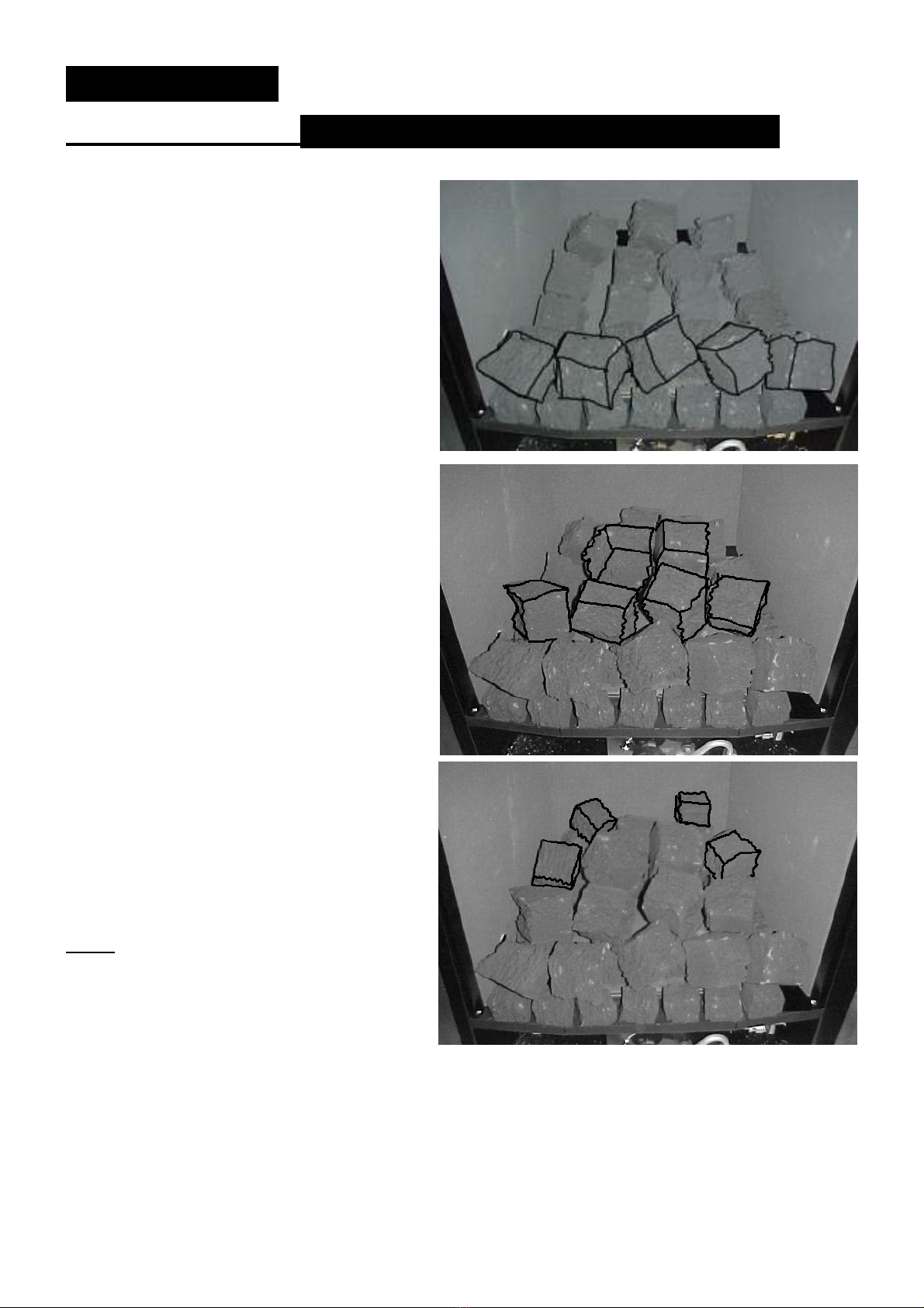
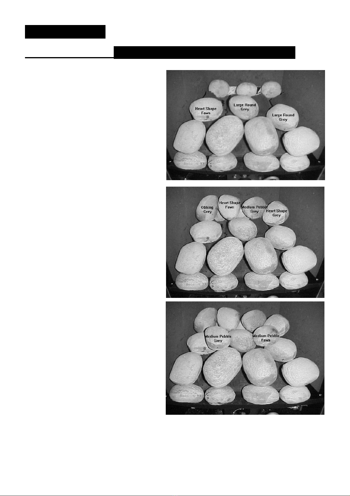
(IMPORTANT) see fuel bed layout procedure before attempting to replace loose fuel bed
components, which should only be replaced as a complete set with no extra components.
P LOT L NT NG
Check pilot aeration holes for linting, use a vacuum cleaner nozzle taking care not to damage
the pilot head. (This should be done every time the fire is serviced)
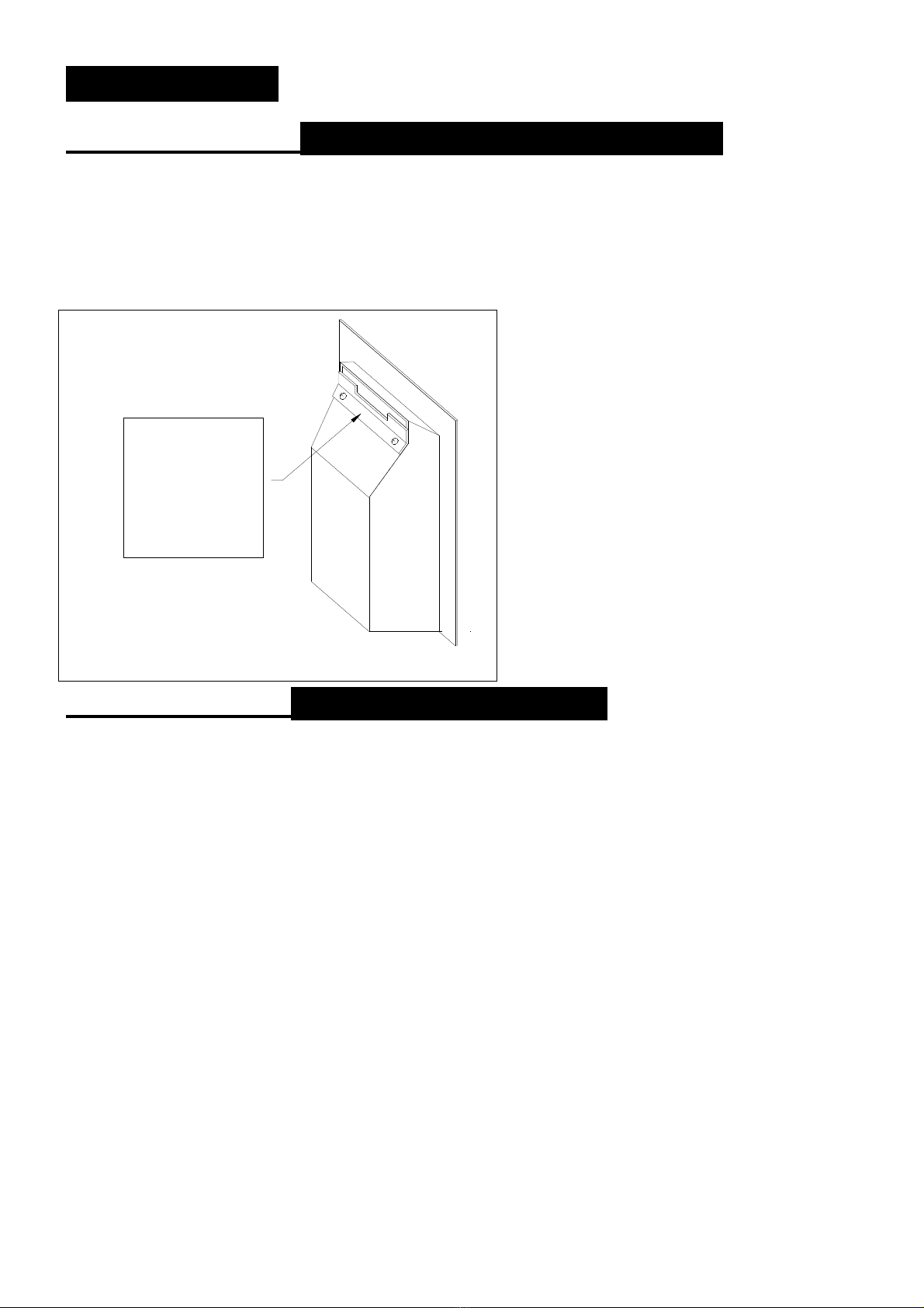
REPLACEMENT OF GAS CONTROL
1. Turn off the gas supply by isolating cock.
2. Lift away carefully fire fret.
3. Lift away carefully all loose fuel bed components.
4 Lift away carefully base boards.
5 Disconnect gas supply from inlet elbow of appliance (right of gas control)
6 Undo and remove two lower screws from fixing plate at front of appliance.
7 Undo and remove two screws securing the tray to the back support.
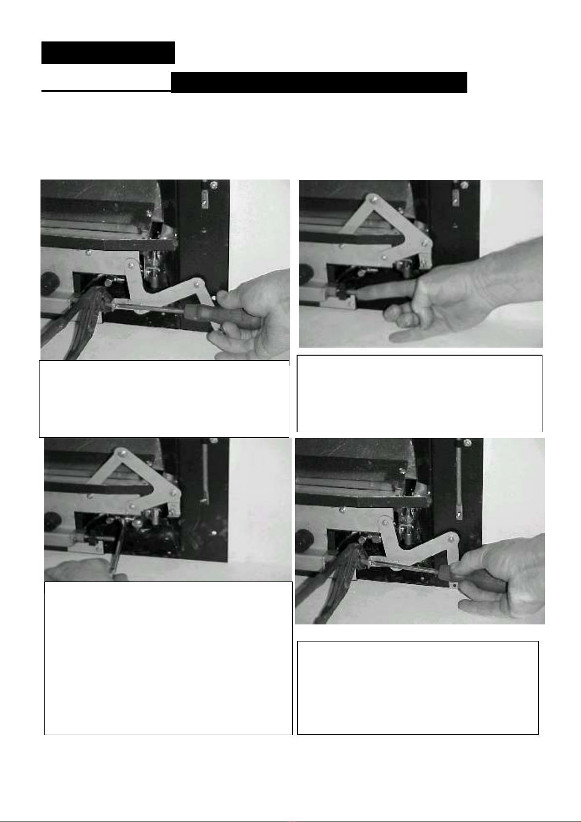
8 Undo the nut at the lower end of the slide control lever and separate it from the link
9 Lift away the appliance burner tray from the main casing.
10 Disconnect the three compression gas connections from the gas control.
11 Undo the thermocouple connection from the rear of the gas control tap.
12 Undo the screw in the centre of the gas control spindle and remove from linkage.
13 Undo and remove the two screws securing the gas control valve to assembly.
14 ervice or replace gas control tap as necessary.
15 Re-assemble the in reverse order.
16 Turn on the gas supply, check for soundness and re commission appliance.