Important Safety Advice
When using electrical appliances, basic precautions
should be followed to reduce the risk of fire, electric
shock, and injury to persons, including the following:
If the appliance is damaged, check immediately with
the supplier before installation and operation.
Donotusethisapplianceintheimmediatesurroundings
of a bath, shower or swimming pool.
This heater must not be located immediately below a
fixed socket outlet or connection box.
Do not use outdoors.
WARNING:ModelLVA191 has two fan heatergrillesone
either side of the screen. These grilles must not be
obstructed or covered in any way. Aminimum distance
of 250mm clearance either side must be maintained,
see installation instructions.
Whenthefans are operating in the heat setting the grilles
become hot and care must be taken not to touch them.
WARNING:DO NOT OBSTRUCTAIRVENTSATTHETOP
AND BOTTOM OF THE APPLIANCE AS CONSEQUENT
OVERHEATINGCANCAUSEDAMAGE
In the event of a fault switch off the appliance.
Switch off the appliance when not required for long
periods.
This appliance is not intended for use by children or
other persons without assistance or supervision if their
physical, sensory or mental capabilities prevent them
from using it safely. Children should be supervised to
ensure that they do not play with the appliance.
If the supply cord is damaged, it must be replaced by a
special cord or assembly available from the
manufacturer or its service agent.
Warning - No naked flame sources, such as candles,
should be placed on this apparatus.
Warning- The appliance shall not be exposed to dripping
or splashing and that no objects filled with liquid, such
as vases, shall be placed on the apparatus.
Warning - this appliance is of Class I construction and
must be connected to a mains outlet with protective
earthing connection.
WARNING:INORDERTOAVOIDOVERHEATING,DO
NOTCOVERTHEHEATER.
The heater carries the Warning symbol, indicating that it
must not be covered.
Electrical
WARNING –THISAPPLIANCEMUSTBE EARTHED
This appliance must be used on an AC
~
supply only and
the voltage marked on the appliance must correspond to the
supply voltage.
Donot switchthe appliance onuntil properly installed. Please
read all the safety warnings and operating instructions.
LivingArt Range
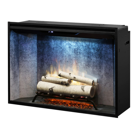
Model(s): LVA191 - LVA191NH
IMPORTANT:THESEINSTRUCTIONSSHOULDBEREADCAREFULLYANDRETAINEDFORFUTUREREFERENCE
General
Unpack the appliance carefully and retain the packaging for
possible future use, in the event of moving or returning the
appliance to your supplier.
Contents of Carton
• Living Art Fire
• Wall fixing plate (attached to LivingArt Fire for transit)
• Fixing screws and wall plugs
• Remote control and batteries (AAA type)
• Cable.
Product Features.
Selection of 8 different scenes.
Appropriate sound effects for each scene.
Sound volume control.
Twin fan heaters with optional hot or cold blow.
(On LVA191only)
Fan heaters combined heat output 1100W @ 230V.
(On LVA191only)
Multiple fixing wall plate for simple and secure wall
mounting.
Provision for manual operation.
Remote control of scene selection, sound, fan heater
switching and standby option.
Styled remote control with easy to follow visual icons.
Red indications of standby mode and fan heater in
operation. (On LVA191only)
Easy to maintain in pristine condition.
Secure CF memory card factory fitted.
Installation
Warning.
This heater must not be located immediately below a fixed
socket outlet.
Maintain the fan heater clearance of 250mm on both sides
of the appliance as shown. - see Fig.1.
Do not obstruct air vents at the bottom and top of the
appliance as consequent overheating can cause damage.
Do not connect the appliance until properly fixed to the
wall and the instruction leaflet is read fully.
At installation of the appliance, care must be taken not to
damage any cables that may be concealed in the wall.
Please be careful while drilling the holes.
These models are designed to be permanently wall mounted
- see Fig.1 for recommended fixing dimensions from floor to
underside of the appliance for optimum viewing of the display
screen. The outline of the chassis and the position of the
electrical socket are shown as dotted outlines in Fig.1 ‘b’.
Any dimensions indicated * are recommended dimensions.
The wall plate is secured to the chassis with 2 screws (see
Fig.4 detail ‘X’,’1’). To wall mount the appliance first remove
the wall plate from the chassis by removing the two screws
and rotating the corner hinges away from the chassis.
Note : Retain the two screws for future use.
Fix the wall plate to the wall using the wall plugs and screws
provided. (Note: Ensure that the wall is suitable for the screws
& plugs provided).


