LT4935 (1:01/08) 12
PRE-CAST FLUE BLOCK
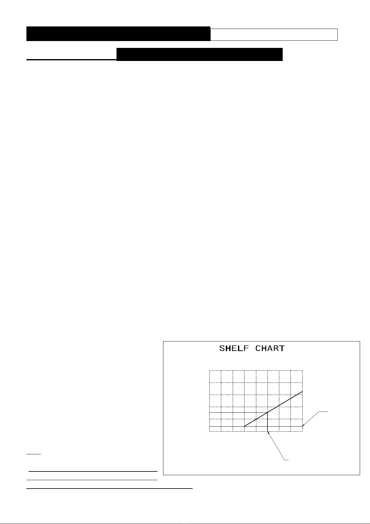
ADDITIONAL DEPTH INCLUDING PLASTER AND FIREPLACE
"A"
"X" MINIMUM (INCLUDING PLASTER)
"A"
300
320
NONE
SPACER
20mm 30mm
30
15
10
0
0
0
340 -440
ALL DIMENSIONS IN mm
"A"
740 Min.
W en "A"=150
-
170 OR 140 MIN. IF FLUE HAS NEVER BEEN USED
FOR SOLID FUEL
120 Min.
340Min.-440Max.
640 Min.
550 MIN.- 570 MAX.
OR 500 MIN.-520 MAX.
FOR LOW OPENING
VERSION
300 Min.
50 Min.
ENIGMA II SLIMLINE SLIDE
Installation Instructions
SECTION EIGHT Siting the Appliance
Spacers are available in t e following sizes 42mm, 30mm and 20mm t ese may be used to
reduce t e minimum dept required.
T e fire can be installed in t e following flues and locations:-
• CLASS ONE
A conventional brick or stone c imney, wit t e
builder's opening constructed of non-combustible
material as used for a solid fuel appliance, wit a
minimum effective cross-sectional dimension of
225 x 225 mm (9 x 9 ins) or a lined flue (e.g. clay,
metal etc.) wit a minimum diameter of 125 mm (5
ins), wit a minimum effective overall eig t of 3
metres (10 ft). A builder's opening a minimum of
550 mm ig (or 500mm wit Low lintel version)
and 350 mm wide wit a minimum dept of 170mm
(or 140mm if flue as never been used for solid
fuel) to allow sufficient volume for debris collection.
Any permanent flue restriction or variable dampers
s all be removed or locked fully open. T e
c imney s ould be swept prior to installation if not
new or previously used wit a gas appliance.
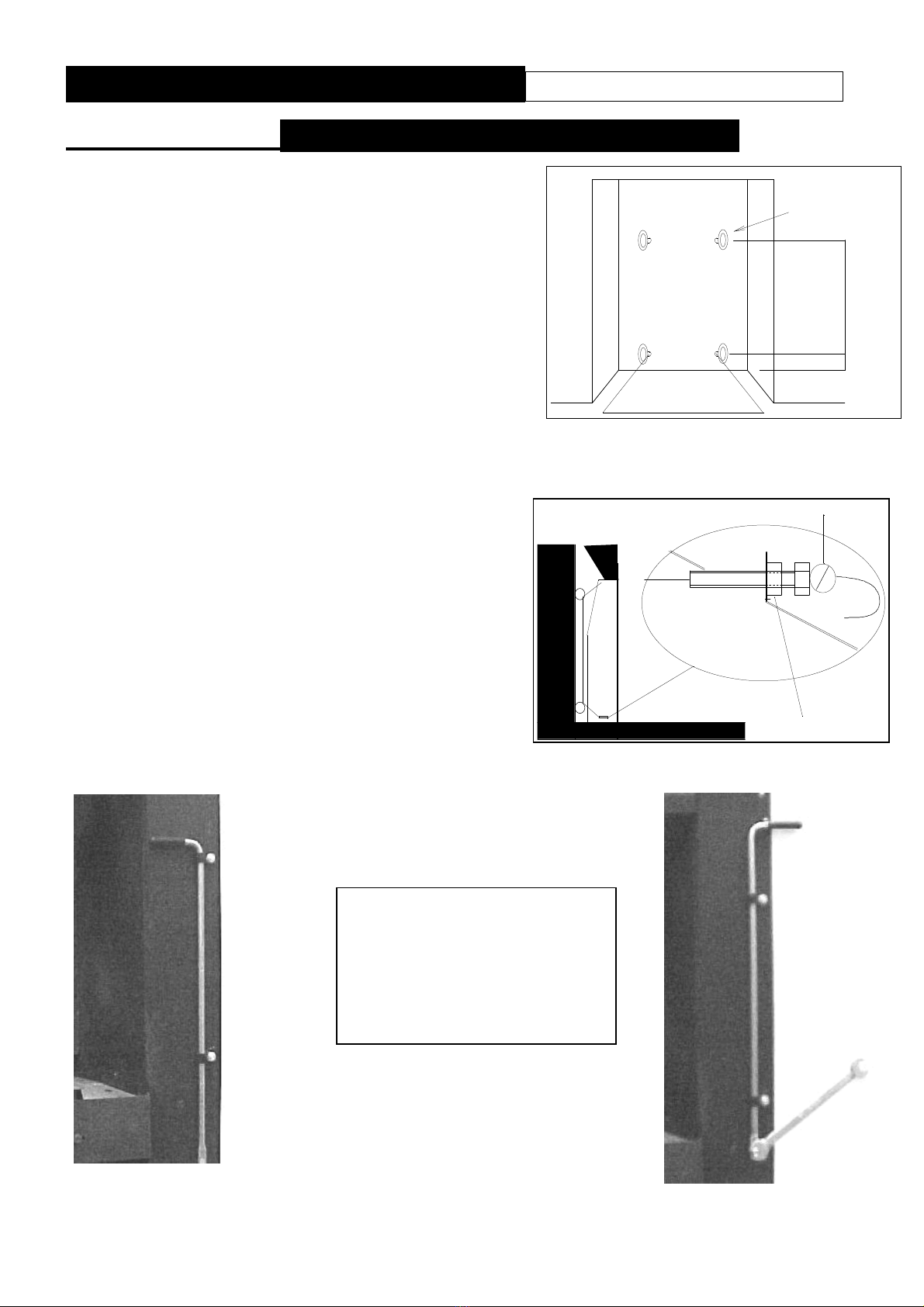
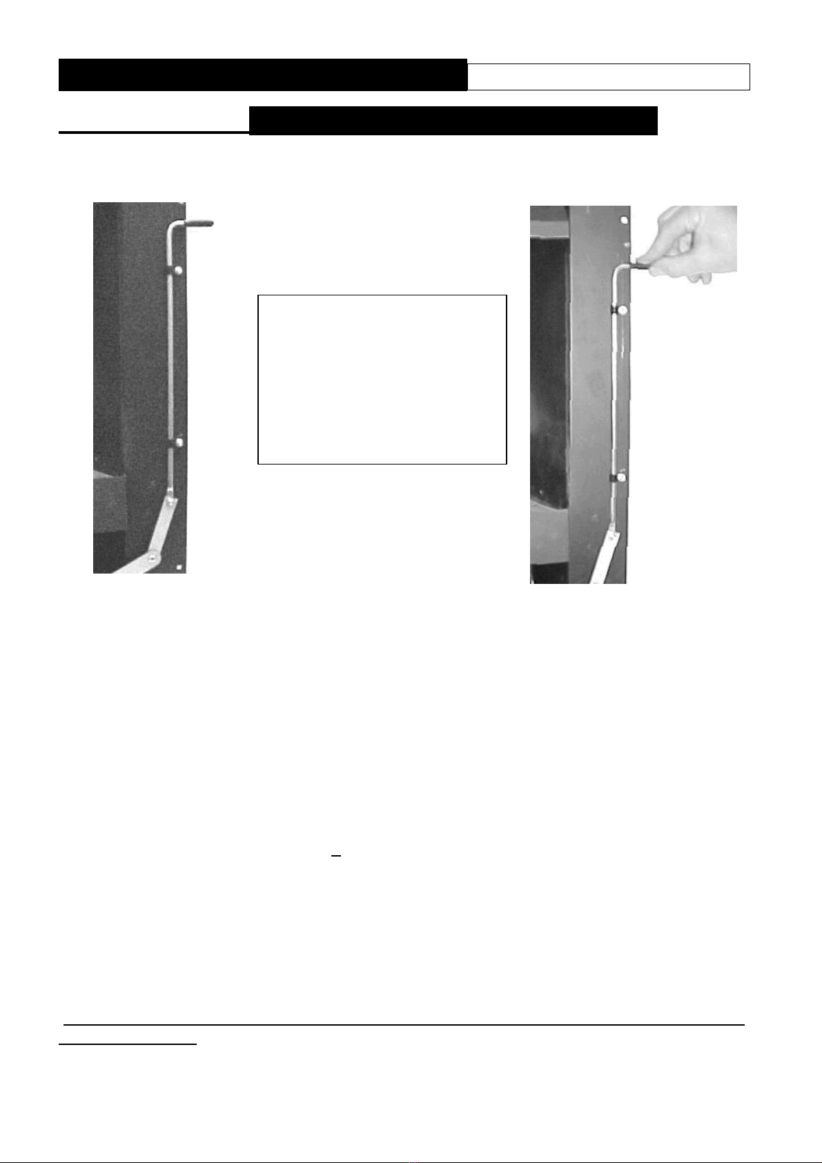
IMPORTANT: - Leave the restrictor plate
upright when installing the appliance into
150mm (6”) diameter flue or larger. Bend down
the restrictor plate if the appliance is installed
into a 125mm (5”) diameter flue or pre-cast
flues.
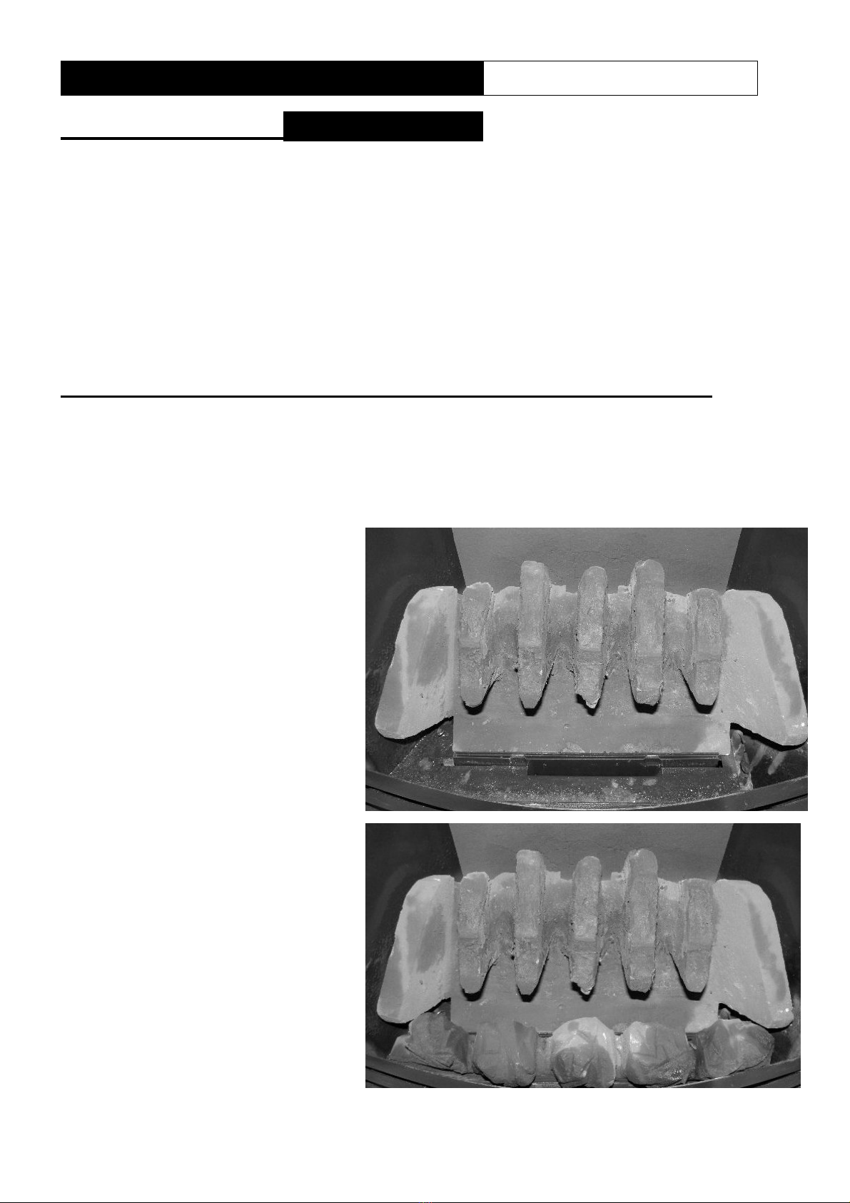
CLASS TWO
Pre-cast
A pre-cast flue correctly constructed conforming to
t e requirements of BS 1289: 1975, 1986 or 1989
wit a minimum effective overall eig t of 3 metres
(10 ft) w ic is correctly terminated (see BS 5440).
It will normally require an additional t ickness of
25mm in t e form of a fireplace back panel or if it is
intended to be fitted back to t e plaster
line t en a spacer may be required to meet wit t e
minimum dept requirement.
IMPORTANT: - Do not fit the restrictor plate if
the appliance is installed into this type of flue.
Note: An inspection s ould be made to ensure t at
t e internal walls of t e flue are clear of mortar fangs. It is recommended t at t e plasterwork
s ould not be directly bonded to t e surface of t e flue blocks, ensuring t at t ere is a small air
gap between t e flue blocks and t e wall surface. T e fire can be installed wit t e plasterwork
being directly bonded to t e flue blocks but t ere is a risk of surface cracking occurring to t e
plaster above t e appliance.