LT4934 (1:01/08)
14
ENIGMA II SLIMLINE Installation Instructions
SECTION NINE T Install the Appliance
CHECKING THE FLUE AND FIRE OPENING
•
Check that the chimney conforms to the required specifications as previously stated.
Examine the condition and carry out any remedial work.
•
If the flue has been used for solid fuel it should be swept prior to the installation.
•
Prior to installin the appliance a smoke test (usin a smoke bomb) should be carried out to
check that satisfactory smoke clearance has been established. If all the smoke is not drawn
into the flue, pre-heat the flue with a blowtorch or similar and re-check. If there is any
uncertainty examine for the cause and, if necessary, seek expert advice.
•
When installin this appliance a ainst a dry lined (plasterboard) wall ensure that any void
between the plasterboard and the wall is sealed with a suitable non combustible material
(i.e. plaster or mortar).
CONNECTING THE GAS SUPPLY
Determine where the as supply is to be connected to the appliance. This may be done from
the front of the unit from either the left or ri ht side, or a concealed fittin from the rear.
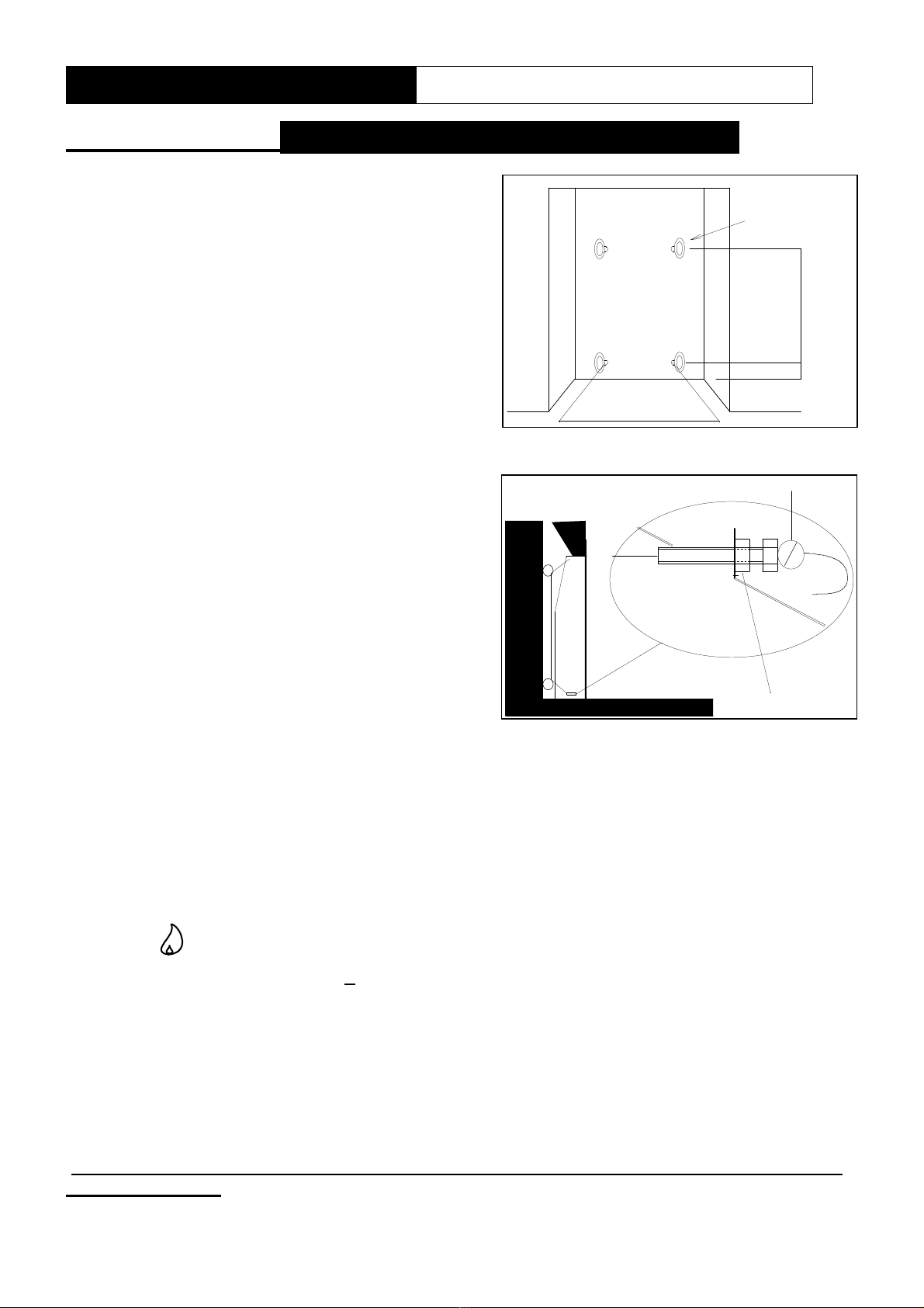
C ncealed gas c nnecti n (fr m the rear)
Note: It may be necessary to remove the burner (2 screws) to aid installation.
•
If the supply is to be a concealed connection it would be advisable to route the supply to the
ri ht side of the unit, takin into account the requirements of BS 6891 1988 dealin with
enclosed pipes.
•
A blind rommet is fitted to the rear of the appliance for the entry of the as pipe (a hole
should be cut in the rommet to fit the supply pipe the rommet must be put back into place
to seal box).
•
An 8mm restrictor elbow is provided on the ri ht-hand side with a compression connection at
the outlet.
•
The pipe can then be routed under the burner tray and onto the inlet elbow.
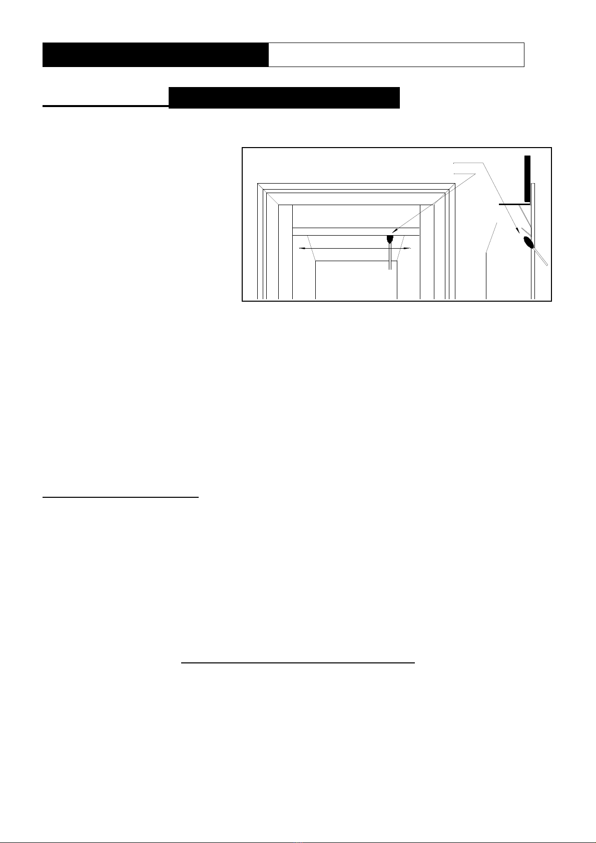
Visible gas c nnecti n (t the fr nt, fr m the left r right)
•
Connections may be made from the front of the appliance from either the left or ri ht in 8mm
diameter pipe.
•
The inlet elbow should be rotated to the required position and the end of the 8mm as feed
pipe formed to route under control and into the inlet elbow.
•
A suitable means of isolation must always be fitted in the supply feed to the fire to facilitate
servicin .
FIXING BACK TO OPENING
•
Remove the paper backin from the len th of foam seal and stick it to the rear flan e of fire.
•
If a spacer box is oin to be used stick the second len th around the rear face of the
spacer unit,. THE FOAM SEAL MUST BE POSITIONED TO ENSURE AN AIR TIGHT SEAL
WHEN THE APPLIANCE IS FITTED.
•
DO NOT use permanent sealin compounds i.e. silicone sealant this could cause the
appliance to be dama ed when it is removed for servicin .
•
If the spacer box is not bein used, mark position of flan e hole in the fireplace front and fix
firebox in position with wall plu s and wood screws.
•
If spacer box is bein used fix the spacer-box to the fireplace first with wood screws and wall
plu s then screw firebox to spacer box usin screws provided.