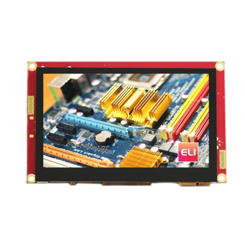
FDI ELI50-CPW User manual

Copyright ©2023, Future Designs, Inc., All Rights Reserved
ELI50-CPW
User’s Manual
Revision 1.0

ELI50-CPW User’s Manual
11/20/2023
Copyright ©2023,
Future Designs, Inc.
Page 2of 16
Important Legal Information
Information in this document is provided solely to enable the use of Future Designs, Inc. (FDI) products.
FDI assumes no liability whatsoever, including infringement of any patent or copyright. FDI reserves the
right to make changes to these specifications at any time, without notice. No part of this document may be
reproduced or transmitted in any form or by any means, electronic or mechanical, for any purpose, without
the express written permission of Future Designs, Inc. 996 A Cleaner Way, Huntsville, AL 35805.
Microsoft, Windows, Windows 10 are registered trademarks of Microsoft Corporation. Other brand names
are trademarks or registered trademarks of their respective owners.
Printed in the United States of America.
For more information on FDI or our products please visit www.TeamFDI.com.
©2023 Future Designs, Inc. All rights reserved.
FDI Document PN: MA00105
Revision: 1.0, 11/20/2023

ELI50-CPW User’s Manual
11/20/2023
Copyright ©2023,
Future Designs, Inc.
Page 3of 16
Important Legal Information.......................................................................................................................... 2
1.0 Introduction......................................................................................................................................... 4
2.0 Recommended Accessories (Purchased Separately)........................................................................... 4
3.0 Touchscreen Precaution ...................................................................................................................... 5
4.0 ESD Warning ...................................................................................................................................... 5
5.0 Determining the Revision of your ELI................................................................................................ 5
6.0 Technical Specifications ..................................................................................................................... 6
7.0 Mechanical Details.............................................................................................................................. 7
8.0 Connectors........................................................................................................................................... 7
9.0 Power Details ...................................................................................................................................... 8
10.0 Touch Activity LED.......................................................................................................................... 11
11.0 Extended Display Information Data (EDID) .................................................................................... 11
12.0 PWM Control of Backlight............................................................................................................... 12
13.0 Support.............................................................................................................................................. 16
13.1 Where to Get Help......................................................................................................................... 16
13.2 Useful Links .................................................................................................................................. 16

ELI50-CPW User’s Manual
11/20/2023
Copyright ©2023,
Future Designs, Inc.
Page 4of 16
1.0Introduction
About ELI (the Easy LCD Interface)
ELI®is Future Designs, Inc.’s family of long-life, plug-and-play embedded displays. ELI
products are true modular embedded display solutions that require no engineering or lead-time.
All ELI products are compatible with a wide range of single board computers including
Raspberry Pi, BeagleBone Black and Windows-based units. FDI designed ELI as an embedded
display option that requires minimal development time to help customers reach production
quickly. Once a product is in production, FDI’s 10 to 15 year ELI product availability
guarantee helps ensure production schedules without the risk of expensive or time consuming
redesigns. Learn more about ELI at TeamFDI.com/ELI.
ELI Compatibility
ELI products are compatible with most Single Board Computers, PCs, and operating systems.
See https://www.teamfdi.com/product-details/eli50-cpw#compatibility for the results of FDI’s
compatibility tests with popular operating systems and platforms. Our results, as indicated in
the table, demonstrate ELI versatility but the table is not exhaustive. ELI products are designed
to work with any single board computer that has an HDMI or DP output. To submit a question
about ELI compatibility with a platform or operating system that is not included in the table,
Your ELI Experience
Share your experience connecting ELI devices to various (single board) computers at:
http://www.teamfdi.com/edid/#edidform.
2.0Recommended Accessories (Purchased Separately)
•7.5V to 17V DC (+/- 5%) Power Supply, with a center positive barrel connection.
•Power Input Cable (FDI P/N: ELI50-CPW-PIC) available from DigiKey or Mouser.
•Or build your own Power Input Cable using these items.
o2.1mm I.D. x 5.5mm O.D. Jack to Screw Terminal, on DigiKey PN: 1528-1386-ND
o4-pin, 1.5mm Molex connector for power input, Molex PN: 502578-0400
o24AWG 225mm, male-male Molex cables for power input
▪Red Molex PN: 2157102125
▪Black Molex PN: 2157101125
oSee Figure 3. ELI50-CPW-PIC Power Input Cable for a visual reference.
Note: All ELI units operate from +12V DC so this is the recommended power supply input
voltage for the entire Family. See section 9.0, Power Details, for more information.

ELI50-CPW User’s Manual
11/20/2023
Copyright ©2023,
Future Designs, Inc.
Page 5of 16
•USB Type A to Mini Type B Cable (for touch)
•HDMI Cable (Type A Male)
•Lengths for the USB and HDMI cables will be determined by the ELI mounting location and
position in each user application.
3.0 Touchscreen Precaution
When the ELI50-CPW is powering up and initializing, please refrain from touching the front of the
display or laying it face down on a surface. This can interfere with proper touchscreen initialization
and may cause temporary issues with the touch screen operation. If this condition occurs, please
reset, or power up the unit correctly and normal touchscreen operation will resume.
4.0ESD Warning
Figure 1. Electrostatic Sensitive Device
Our ELI units are shipped in a protective anti-static package. Do not subject the module to high
electrostatic potential. Exposure to high electrostatic potential may cause damage to the boards that
will not be covered under warranty. General practice for working with static sensitive devices
should be followed when working with this device.
5.0Determining the Revision of your ELI
All ELI devices have a label placed on the board to identify the part number and revision of the
unit. This label will help you quickly and correctly identify your ELI unit’s part number and
revision number.
An example of an ELI label is shown below.
ELI Part Number ELI Revision Number

ELI50-CPW User’s Manual
11/20/2023
Copyright ©2023,
Future Designs, Inc.
Page 6of 16
6.0Technical Specifications
Table 1. Technical Specifications
Screen Size (diagonal inches):
5.0
Display Technology:
a-Si TFT LCD
Resolution:
720 x 1280 (WXGA Portrait)
Brightness (nits typical):
300
Contrast Ratio (typical):
1000:1
Aspect Ratio:
Tall 9:16
Interface Input Mode:
HDMI
Colors:
16.7M (24 bit)
Horizontal Viewing Angle:
85/85°
Vertical Viewing Angle:
85/85°
Surface:
1.1 mm anti-fingerprint treated glass
Touch Screen:
Projected Capacitive
Touch Screen Interface (mA typical/max):
USB Device
Touch Panel Hardness:
6H
Active Area (in mm, W x H):
62.10 x 110.40
Response Time (ms):
30
Backlight:
12 LEDs
Backlight Life (K hours typical):
30
Backlight Power Consumption (W Typical):
Up to 61% of total
Operating Temperature:
-20° to 70° C
Storage Temperature:
-30° to 80° C
Input Voltage:
7.5 to 17 VDC +5%
Power Consumption (mA, typ/max):
150/250 @ 12V
USB Power Consumption (mA, typ/max):
< 1mA (touch is powered from 12V)
RoHS Compliant:
Yes
Dimensions (in mm W x H x D)
71.61 x 145.36 x 6.26
Mounting:
3M 300LSE tape or other 3M tape
Weight (grams)
94

ELI50-CPW User’s Manual
11/20/2023
Copyright ©2023,
Future Designs, Inc.
Page 7of 16
7.0Mechanical Details
A 2D Mechanical Drawing of the unit is available on our website under the Documentation tab.
https://www.teamfdi.com/product-details/eli50-cpw
3D Mechanical Models (in both STEP and EASM format) are available from our website after
completing a simple fillable NDA or Non-Disclosure Agreement.
https://www.teamfdi.com/mechanicalmodelrequest
8.0Connectors
Figure 2. ELI50-CPW Connectors

ELI50-CPW User’s Manual
11/20/2023
Copyright ©2023,
Future Designs, Inc.
Page 8of 16
9.0Power Details
A 12VDC +/- 5% power supply with a 2.0A output will power most any product from the ELI
Family. This allows a common, off-the-shelf power supply such as the 1939-1462-ND to be used for
quick demos or prototyping across the entire ELI Family. In general, any 12VDC power supply with a
2.1mm center positive connection will be acceptable if it can provide enough current to power the
particular ELI unit being used.
On the ELI50-CPW, a Power Input Cable is available to help easily power the unit for prototyping
and testing. This cable is available from DigiKey or Mouser under P/N ELI50-CPW-PIC or you can
build your own using the information given below and in Section 2.0, Recommended Accessories
(Purchased Separately).
Figure 3. ELI50-CPW-PIC Power Input Cable

ELI50-CPW User’s Manual
11/20/2023
Copyright ©2023,
Future Designs, Inc.
Page 9of 16
When ready, connect power via the cable into the power connector (J6).
Pin
Value
1
Positive Power Input
2
Positive Power Input
3
Ground
4
Ground
J6 Pinout
Mating Connector Details for J6:
•Manufacturer: Molex
•Part Number: 502578-0400
•Digi-Key Housing Link
•Pre-terminated wires:
•Digikey Red Link
•Digikey Black Link
LED4 is the “Power” LED indicator that is on if the ELI is connected to a DC input voltage.
LED1 is the “LCD Power” indicator and LED3 is the “LCD 6V0 Power” Indicator. When DC
input power is applied to the unit (via J6) and an HDMI input signal is present at J2, LED1 and
LED3 will turn ON (LED1 is Orange and LED3 is Yellow). This LCD Power indicator only
confirms that a DC input voltage and an HDMI signal are “present”at the ELI50-CPW inputs, but
it does not mean that the input signals are necessarily valid or correct.
Figure 4. ELI50-CPW LEDs

ELI50-CPW User’s Manual
11/20/2023
Copyright ©2023,
Future Designs, Inc.
Page 10 of 16
ELI50-CPW units can use power supplies ranging from +7.5 to +17.0 VDC + 5% (2.0A).
For volume production applications, the input power can be optimized for your ELI unit and lower
capacity power supplies can be used.
To verify that the ELI50-CPW unit is correctly powered you may check the input voltage with a
Fluke multi-meter or scope by probing test point TP5, shown below. Please verify that the input
voltage is present, and within the +/- 5% tolerance and is free from excessive noise or AC ripple.
Note: If using an input that is within the 7.5V to 17.0V (+/- 5%) range of an ELI50-CPW,
the voltage measured from TP5 will reflect the input voltage being utilized.
Figure 5. ELI50-CPW Test Point TP5. Probe to measure input voltage
Note on Proper Power Up Sequence:
The ELI50-CPW must be powered on before the SBC video source to ensure that the EDID
information can be read properly to auto initialize the correct screen resolution and timing.
Some Single-Board Computers or other HDMI video sources might only read the EDID
information when the video source is first powering up, so it is critical to make sure that the
ELI50-CPW is powered up first to assure proper initialization of the video / screen resolution.

ELI50-CPW User’s Manual
11/20/2023
Copyright ©2023,
Future Designs, Inc.
Page 11 of 16
10.0 Touch Activity LED
ELI50-CPW has a Touchscreen Activity LED (LED2) located near the USB touch Interface (P2):
Figure 6. ELI50-CPW –Touch Activity LED
This Green LED2 will stay on when the USB touch interface is connected and blink whenever any
touchscreen input is detected, allowing for verification of the touch response.
Note that no touch response will be read if the HDMI is disconnected, or the ELI display is not
detected by the video source.
11.0 Extended Display Information Data (EDID)
ELI uses Extended Display Identification Data (EDID) for automatic configuration with many
operating systems. You can find out more on our website at http://www.teamfdi.com/edid/.
The ELI50-CPW must be powered on before the SBC video source to ensure that the EDID can
be read properly.
Some Single-Board Computers or other HDMI video sources might only read the EDID
information when the video source is first powering up, so it is critical to make sure that the
ELI50-CPW is powered up first to assure proper initialization of the video / screen resolution.

ELI50-CPW User’s Manual
11/20/2023
Copyright ©2023,
Future Designs, Inc.
Page 12 of 16
12.0 PWM Control of Backlight
Figure 7. PWM Backlight Control
NOTE: For Rev 1.x units the PWM feature is not implemented but will be supported in future
revisions.
J4 mating connector housing information:
•Manufacturer: Hirose
•Part Number: DF12-3S-1.25C
•Digi-Key Link: https://www.digikey.com/products/en?keywords=H2180-ND
•Pre-terminated wires https://www.digikey.com/en/products/filter/jumper-wires-pre-crimped-
leads/453?s=N4IgjCBcoLQCxVAYygMwIYBsDOBTANCAG4B2aWehA9lANogDsAHAG
wgC6hADgC5QggAvsKA
ELI provides an input, so an external processor or SBC can control the backlight to vary the display
brightness or to reduce power consumption (the display backlight is typically one of the larger
sources of power consumption in the unit). PWM dimming is an input with a 0 to 3.3 VDC range and
the user should drive this with a push-pull type output or a suitable open collector output.
To control the display, backlight the user should connect an externally generated Pulse Width
Modulated (PWM) signal to J4 pin 2 along with a common ground to J4 pin 3. The frequency range
for this signal is from 5KHz to 100KHz. Each ELI unit’s display backlight properties will vary, so the
user should test their version for an acceptable range of brightness control. For example, your 0 to
100% brightness range may be 40% to 90% of the PWM range. In certain installations, a series
resistor on J4 pin 2 may be required to ensure a clean PWM signal is provided to the ELI. The
suggested value for the resistor is 100ohms. See Figure 9 below, for example of connectivity. Actual
testing in your installation may require this resistor to be changed, or possibly not required at all.
On the ELI unit, the PWM dimming signal is pulled up to LCD_VDD providing 100% backlight
power when no PWM signal is applied at pin 2 of J4. If nothing is connected to J5 the ELI will drive

ELI50-CPW User’s Manual
11/20/2023
Copyright ©2023,
Future Designs, Inc.
Page 13 of 16
the display at 100% brightness (default).
The LCD_VDD output at pin 1 of J4 is a 3.3VDC ± 5%. If the external system is capable of directly
driving the PWM dimming signal at 3.3VDC, there is no need to connect pin 1 to the cable. ELI
provides the 3.3 VDC signal, called LCD_VDD, for the external system in case this voltage is needed
to generate the correct levels on the PWM dimming input.
Figure 8. ELI50-CPW Backlight Curve in Nits
0%
20%
40%
60%
80%
100%
300.2
287.0
276.0
263.0
249.0
235.0
221.0
207.0
192.0
178.0
164.0
149.0
134.5
120.0
104.8
90.2
75.1
60.1
45.0
30.0
15.1
ELI50-CPW
50 KHz
Brightness

ELI50-CPW User’s Manual
11/20/2023
Copyright ©2023,
Future Designs, Inc.
Page 14 of 16
Figure 9. Raspberry Pi Signal and Ground
The ELI backlight can be easily controlled from a Raspberry Pi. See Figure 9 for a wiring diagram. Our
software is available on the website at https://www.teamfdi.com/product-details/eli50-cpw#software or
you may copy the code from here:

ELI50-CPW User’s Manual
11/20/2023
Copyright ©2023,
Future Designs, Inc.
Page 15 of 16
/* Changes brightness of ELI backlight given a command line argument between 0 and the set
range. Uses bcm2835 header file provided by Broadcom at http://www.airspayce.com/mikem/bcm2835/bcm2835-
1.52.tar.gz This source code must be compiled using "g++ brightness.cpp -o brightness -l
bcm2835"in order to properly link the header file. Must be run using sudo, accessing GPIO
pins requires root permissions. After compiling, you may add executable to "/usr/bin" which
allows you to type "sudo brightness <value>" to change brightness anywhere in terminal (“sudo
brightness 20” is full brightness). The "/boot/config.txt" file must also be changed by
adding a "#" before the line "dtparam=audio=on". This disables audio output from the
Raspberry Pi. If this is not disabled then anytime sound is output the screen will return to
100% brightness.
*/
#include<iostream>
#include<bcm2835.h>
#include<string>
using namespace std;
#define LED RPI_GPIO_P1_12 // PWM pin number for backlight control
#define RANGE 20 // Range for PWM steps
#define CLOCK 192 // Clock rate
int main(int argc,char *argv[]){
int data =0;// Brightness level
if(argc != 2){ // Give user correct usage if ran incorrectly
cout << "Error: correct usage, brightness <value>" << endl;
return 1;
}
data =stoi(argv[1]);
if(data >RANGE || data <0){
cout << "Error: brightness value must be between 0 and " << RANGE << endl;
return 1;
}
if(!bcm2835_init())
return 1;
bcm2835_gpio_set_pad(BCM2835_PAD_GROUP_GPIO_0_27,BCM2835_PAD_DRIVE_2mA); // Sets the
drive current to 2mA
bcm2835_gpio_fsel(LED,BCM2835_GPIO_FSEL_ALT5); // Sets up pin 18 for alt5 pwm mode
bcm2835_pwm_set_clock(CLOCK); // Sets pwm clock to 19.2 MHz / CLOCK
bcm2835_pwm_set_mode(0,1,1); // Sets mode to markspace
bcm2835_pwm_set_range(0,RANGE); // Sets range
bcm2835_pwm_set_data(0,data); // Sets data rate to argument value
bcm2835_close();
return 0;
}
Figure 10. Backlight Control for Raspberry Pi

ELI50-CPW User’s Manual
11/20/2023
Copyright ©2023,
Future Designs, Inc.
Page 16 of 16
Figure 11. Renesas Synergy S7G2 Signal and Ground
As an example, the ELI backlight can also be controlled from a Renesas Synergy S7G2 wired as
shown in Figure 11. The software for Synergy can be found on our website at
https://www.teamfdi.com/product-details/eli50-cpw#software.
13.0 Support
13.1Where to Get Help
Online technical support is available at http://www.teamfdi.com/support/
13.2Useful Links
•Future Designs, Inc. Forums: https://www.teamfdi.com/forums/
•ELI50-CPW Product Page: http://www.teamfdi.com/product-details/eli50-cpw
•ELI Software User’s Manual: http://www.teamfdi.com/wp-content/uploads/ELI-Software-
Users-Manual.pdf
•Tell us about your ELI experience: http://www.teamfdi.com/edid/#edidform
•EDID Information Page: http://www.teamfdi.com/edid/
Table of contents
Other FDI Control Unit manuals
Popular Control Unit manuals by other brands

FMI
FMI GA9050A-1 Series manual

Beijing ART Tech
Beijing ART Tech PCI8735 user manual

Truma
Truma Panel MES Module A Operating instructions & installation instructions

INSTEON
INSTEON 2635-222 owner's manual

Pilz
Pilz PSSuniversal PSSu H F PN operating manual

Copley Controls
Copley Controls Accelnet Plus AEV-090-14 user guide

CIAT
CIAT XtraConnect 2 Installation, Operation, Commissioning, Maintenance

Danfoss
Danfoss EVR 2 installation guide

Honeywell
Honeywell Esser IQ8TAL Installation instruction

DeZurik
DeZurik PTW manual

Frequency Central
Frequency Central Bartos Flur Rev(2) Build documentation

Genie
Genie Aladdin Connect Quick setup guide