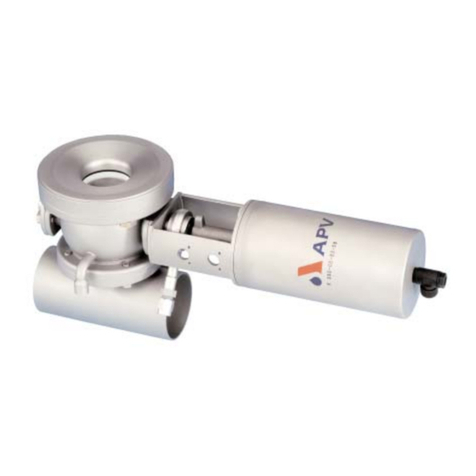
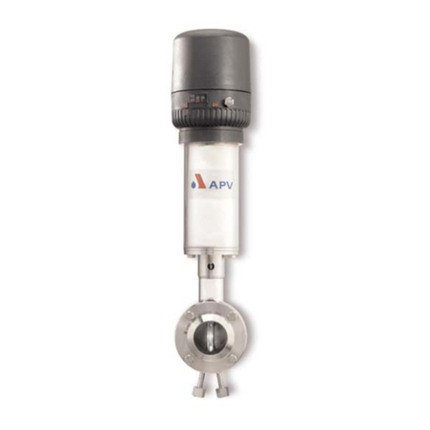
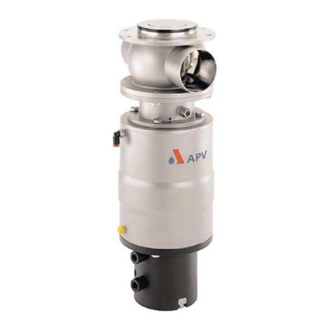
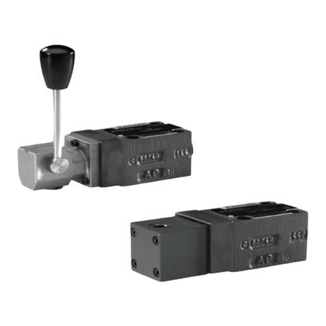
SPX APV DELTA UF3 User manual

Operating Manual
DELTA UF3(A)/UFR3(A)
Relief Valve
Read and understand this manual prior to
operating or servicing this product.
www.sks-online.com
www.sks-webshop.com

www.sks-online.com
www.sks-webshop.com

Declaration of Conformity
for Valves and Valve Manifolds
SPX Flow Technology Rosista GmbH, Zechenstr. 49, D-59425 Unna-Königsborn
herewith declares that the
double seat valves of the series D2, SD4, SDT4, SDM4, SWcip4, DSV,
DA3, DE3, DEU3, DET3, DKR2, DKRT2, DKRH2
in the nominal diameters DN 25 - 150, 1“ – 6“ and 1 Sh5 - 6 Sh5
butterfly valves of the series SV1 and SVS 1 F
in the nominal diameters DN 25 - 100, DN 125 - 250 and 1“ – 4“
ball cocks of the series KH, KHV
in the nominal diameters DN 15 - 100
single seat, diaphragm and spring loaded valves of the series
S2, SW4, SWmini4, SWT4, M3, MF3, M4, MF4, MP4, MS4, AP1, APT1, CPV, RG4, RGM4,
RGE4, RGEM4, PR2, PR3, PR4, SI2, UF3, VRA,VRAH
in the nominal diameters DN 10 - 150, 1/2“ – 4“ and 1 Sh5 - 6 Sh5
and the valve manifolds installed thereof
meet the requirements of the Directives 2006/42/EC (superseding 89/392/EEC
and 98/37/EC) and GPSG - 9.GPSGV.
For official inspections, SPX Flow Technology Rosista GmbH presents
a technical documentation according to Appendix VII of the Machinery Directive,
this documentation consisting of documents of the development and construction,
description of measures taken to meet the conformity and to correspond with
the basic requirements on safety and health, incl. an analysis of the risks,
as well as an operating manual with safety instructions.
The conformity of the valves and valve manifolds is guaranteed.
Authorised person for the documentation:
SPX Flow Technology Rosista GmbH, Frank Baumbach, Zechenstr. 49, D-59425 Unna
November 30, 2010
Manager Research and Development
UK
www.sks-online.com
www.sks-webshop.com

www.sks-online.com
www.sks-webshop.com

Content Page
DELTA UF3-UK5.qxp / 06.2008
U
1. General Terms 2
2. Safety Instructions 2
3. Mode of Operation 3
4. Auxiliary Equipment 4
5. Cleaning 5
6. Installation 5 - 6
6.1. Welding Instructions
7. Dimensions / Weights 7
8. Technical Data 8
8.1. General
8.2. Specification of compressed air
9. Maintenance 9
9.1. Assembly Tool
10. Service Instructions 10 - 13
10.1. Dismantling from the line system
10.2. Dismantling of wear parts
10.3. Assembly of spring cylinder
10.4. Installation of seals and assembly of valve
10.5. Installation of valve
11. Service Instructions 14
11.1. Installation of seat seal in valve shaft
12. Trouble Shooting 15
13. Spare Parts Lists 15
UF3 - DN design - RN 01.054.53
Inch design - RN 01.054.570
UF3-A - DN design - RN 01.054.54
Inch design - RN 01.054.571
UFR3 - DN design - RN 01.054.55
Inch design - RN 01.054.573
UFR3-A - DN design - RN 01.054.56
Inch design - RN 01.054.572
UF3 - Inch 3A-design - RN 01.054.574
UF3-A - Inch 3A-design - RN 01.054.575
UFR3 - Inch 3A-design - RN 01.054.576
UFR3-A - Inch 3A-design - RN 01.054.577
1
Relief Valve
DELTA UF 3 (A) / UFR3 (A)
Operating Manual: Rev.5
www.sks-online.com
www.sks-webshop.com

www.sks-online.com
www.sks-webshop.com

1. General Terms
2
Relief Valve
DELTA UF 3 (A) / UFR3 (A)
Operating Manual: Rev.5
DELTA UF3-UK5.qxp / 06.2008
U
This operating manual has to be read carefully and observed by
the competent operating and maintenance personnel.
We have to point out that we will not accept any liability for
damage or malfunctions resulting from the non-compliance
with this operating manual.
Descriptions and data given herein are subject to technical
changes.
2. Safety Instructions
Danger!
- The technical safety symbol draws your attention to important
directions of operating safety. You will find it wherever the activities
described are bearing risks of personal injury.
- Disconnect electrical and pneumatic connections.
- Depressurize the line and cleaning system and discharge the lines,
if possible, before any maintenance work.
-Risk of injury by sudden valve actuation!
- Observe service instructions for a safe maintenance of the valve.
- The valve must only be assembled, disassembled and
reassembled by persons who have been trained in APV valves
or by APV service team members. If necessary, contact your local
APV representative.
- The spring cylinders are preloaded by spring force.
Opening of the actuators is strictly forbidden.
Danger to life!
Actuators which are no longer used and / or defective
must be disposed in professional manner.
Defective actuators must be returned to your
APV Solutions & Services company
for their professional disposal and
free of charge for you.
Please address to your local APV representative.
!
!
!
www.sks-online.com
www.sks-webshop.com

3. Mode of Operation
3Relief Valve
DELTA UF 3 (A) / UFR3 (A)
Operating Manual: Rev.5
DELTA UF3-UK5.qxp / 06.2008
U
The valve has been developed for use in the brewing and
beverage industries, in the dairy and food production as well as
in chemical and pharmaceutical applications.
It deals with an universally applicable valve design featuring high
mechanical reliability and simple servicing.
The UF3/UFR3 relief valve is applied to hold a product pressure or
to discharge a product quantity, as the process requires.
If the preset opening pressure is exceeded, the valve is
opened automatically by the imminent line pressure in the
supply line (A) under the valve seat.
The liquid is drained via the discharge line (B). If the set value
adjusted falls short, the valve is closed by spring force.
The flow direction is always from A B.
Attention:
As defined by the Pressure Equipment Directive 97/23/EC,
the relief valve DELTA UF3/UFR3 is a "pressure accessory"
and not a "safet accessor ",
i.e. it must not be used as safety valve.
A
B
UF 31-A
www.sks-online.com
www.sks-webshop.com

* Seat lift actuator
The UF3 valve can be equipped with a seat lift actuator if required
for cleaning technical reasons.
(see chapter 5.)
* Valve position indication (fig. 4.1)
To indicate the valve position, proximity switches can be mounted
in the yoke area at (C).
We recommend to use our APV standard types.
Operating distance : 5mm / diameter :11mm.
If the customer decides to use a valve position indication other
than APV type, we cannot take over any guarantee for a faultless
function.
* Valve seat variants
Valve seats in flat and conical design, for special applications,
are available. Through the use of a valve seat with regulating
cone (D), the flow behaviour at low through put quantities is
improved and a “softer” valve closing is achieved.
This valve variant is called “UFR3“ (fig. 4.2).
* Housing shapes
Different housing shapes can be applied to reduce dead spaces
to a minimum.
*The spring cylinder is available with scale and hand wheel
to allow for a simple adjustment of the response pressure (fig. 4.3).
* As a special version, the pressure relief valves are available
in aseptic design (with flat diaphragm or metal bellow).
- Deviations from the standard spare parts lists result. These
special drawings and spare parts lists will be supplied separately.
4. Auxiliary Equipment
4
Relief Valve
DELTA UF 3 (A) / UFR3 (A)
Operating Manual: Rev.5
DELTA UF3-UK5.qxp / 06.2008
U
C
scale
hand wheel
0,2
0,6
1,0
1,4
(bar)
regulating cone (D)
fig. 4.1
fig. 4.2
fig. 4.3
www.sks-online.com
www.sks-webshop.com

5Relief Valve
DELTA UF 3 (A) / UFR3 (A)
Operating Manual: Rev.5
DELTA UF3-UK5.qxp / 06.2008
U
Optimum cleaning is given if the seat lift actuator (E) drives
the valve seat into the position “on” during the cleaning process.
During this process, the cleaning liquid can flush the seal
surfaces.
After termination of the cleaning step, the seat lift actuator is
vented and the valve seat is driven into the position “off” by
spring force.
5. Cleaning
6. Installation
- Installation has to be done in such a way that liquids can drain off
the valve housing. Vertical position is preferred.
- Valves can be welded direct into the pipeline.
(valve insert completely dismantable)
- After the installation, the set value must be adjusted by a pressure
gauge.
Adjustment: turn right = pressure increase
turn left = pressure reduction
If required, the value can be corrected during production
by turning the adjusting screw at the spring cylinder.
-Attention: Observe welding instructions.
seat lift actuator (E)
valve seat
fig. 5.1
www.sks-online.com
www.sks-webshop.com

6. Installation
6
Relief Valve
DELTA UF 3 (A) / UFR3 (A)
Operating Manual: Rev.5
DELTA UF3-UK5.qxp / 06.2008
U
6.1 Welding Instructions
UF3
- Before welding of the valve, dismantle the valve insert from the
housing. Proceed carefully to avoid damage.
- Welding may only be carried out by certified welders (EN 287 - 1).
(seam quality EN 25817 ,,B”)
- The welding of the valve housings must be undertaken in such a
way that deformation strain cannot be transferred to the valve body.
- The preparation of the weld seam up to 3 mm thickness must be
carried out in butt manner as a square butt joint without air.
(Consider shrinkage!)
- TIG orbital welding is best!
- After welding of the valve housing or of the mating flanges and after
work at the pipelines, the corresponding parts of the installation or
pipelines must be cleaned from welding residues and soiling.
If these welding instructions are not observed, welding residues
and dirt particles can settle in the valve and cause damage.
- Any damage resulting from the nonobservance of these welding
instructions is not subject to our guarantee.
www.sks-online.com
www.sks-webshop.com

7Relief Valve
DELTA UF 3 (A) / UFR3 (A)
Operating Manual: Rev.5
DELTA UF3-UK5.qxp / 06.2008
U
7. Dimensions / Weights
* without / with regulating cone
** weight without / with seat lift actuator
*** dimensions without / with seat lift actuator
F
* *** *** **
pressure range
(bar)
A1 A2 Ø D F L1 L2 Ø G1
in g
G2
in g
DN Inch flat cone without with DN Inch without with without with
25 1” 0-6,8 0-5,4 310 395 26 22,2 50 360 445 53 2,4 4,9
25 1” 0-10,0 0-10,0 353 438 26 22,2 50 403 488 53 2,6 5,1
40 1,5” 0-3,5 0-2,9 316 401 38 34,9 67 383 468 53 3,3 5,8
40 1,5” 0-7,5 0-6,3 359 444 38 34,9 67 426 511 53 3,5 6,0
40 1,5” 0-10,0 0-10,0 389 474 38 34,9 67 456 541 85 5,6 8,1
50 2” 0-2,1 0-1,8 322 407 50 47,6 72 394 479 53 3,8 6,3
50 2” 0-4,5 0-4,0 365 450 50 47,6 72 437 522 53 4,0 6,5
50 2” 0-10,0 0-10,0 395 480 50 47,6 72 467 552 85 6,1 8,6
65 2,5” 0-1,2 0-1,1 330 415 66 60,3 85 415 500 53 5,2 7,7
65 2,5” 0-2,7 0-2,4 373 458 66 60,3 85 458 543 53 5,4 7,9
65 2,5” 0-7,6 0-7,0 403 488 66 60,3 85 488 573 85 7,5 10,0
65 2,5” 0-10,0 0-10,0 451 536 66 60,3 85 536 621 85 8,0 10,5
3” 0-1,1 0-1,0 333 418 72,9 90 423 508 53 6,6 9,1
3” 0-2,3 0-2,1 376 461 72,9 90 466 551 53 6,8 9,3
3” 0-6,5 0-6,0 406 491 72,9 90 496 581 85 8,8 11,3
3” 0-10,0 0-10,0 454 539 72,9 90 544 629 85 9,3 11,8
80 0-0,9 0-0,8 338 423 81 98 436 521 53 6,7 9,2
80 0-1,8 0-1,7 381 466 81 98 479 564 53 6,9 9,4
80 0-5,2 0-4,8 411 496 81 98 509 594 85 9,0 11,5
80 0-10,0 0-10,0 459 544 81 98 557 642 85 9,5 12,6
100 4” 0-0,6 0-0,5 347 432 100 97,6 111 458 543 53 8,5 11,0
100 4” 0-1,2 0- 1,1 390 475 100 97,6 111 501 586 53 8,7 11,2
100 4” 0-3,5 0-3,2 420 505 100 97,6 111 531 616 85 10,8 13,3
100 4” 0-8,3 0-7,7 468 553 100 97,6 111 579 664 85 11,3 13,8
F A1 (A2)
L1 (L2)
D
Ø
Ø
UF31-A
spring cylinder
with seat lift actautor
www.sks-online.com
www.sks-webshop.com

8
Relief Valve
DELTA UF 3 (A) / UFR3 (A)
Operating Manual: Rev.5
DELTA UF3-UK5.qxp / 06.2008
U
8. Technical Data
8.1 General
housing, housing cover
shafts: 1.4571, 1.4404
spring cylinder, yoke,
intermediate piece, operating cam
screws: 1.4301
seals
standard design: EPDM / PTFE
option: FPM, VMQ, HNBR
max. line pressure: 10 bar
max. operating temperature: 135O C EPDM, HNBR
* VMQ, FPM
short-term load: 140O C EPDM, HNBR
* VMQ, FPM
* (no steam)
air connection: 6 bar
air connection for hose: 6x1
Control pressure of seat lift actuator: 10 bar max. / 6 bar min.
Depending on the size of the spring cylinder, the response
pressure can be adjusted variably or up to max. 10 bar.
! The minimum response pressure can be > 0 bar depending on
the valve mounting position and the friction of the shaft seal.
8.2 Specification of compressed air
compressed air quality: quality class according to
DIN/ISO 8573-1
content of solid particles: qualit class 3
max. size of solid particles per m³
10000 of 0,5µm <d<1,0µm
500 of 1,0µm <d<5,0µm
content of water: qualit class 4
max. dew point temperature + 3°C
For installations at lower
temperatures or at higher altitudes,
additional measures must be
considered to reduce the pressure
dew point accordingly.
content of oil: qualit class 1
max. 0,01mg/m³
(The oil applied must be compatible with Polyurethane
elastomer materials.)
www.sks-online.com
www.sks-webshop.com

9Relief Valve
DELTA UF 3 (A) / UFR3 (A)
Operating Manual: Rev.5
DELTA UF3-UK5.qxp / 06.2008
U
- The maintenance intervals depend on the different applications
and have to be determined by the operator carrying out regular
checks.
- Replacement of seals according to Service Instructions.
Customer stock keeping of spare seals is recommended.
For valve service we supply complete seal kits including
seal grease (see spare parts lists).
-Slightly grease all seals before their installation !!!!!
Recommendation:
APV food-grade grease for EPDM, HNBR and FPM
(0,75 kg/ tin - ref.-No. 000 70-01-019/93)
(60 g/ tube - ref.-No. 000 70-01-018/93)
or
APV food-grade grease for VMQ
(0,60 kg/ tin - ref.-No. 000 70-01-017/93)
(60 g/ tube - ref.-No. 000 70-01-016/93)
!Do not use grease on mineral oil basis for EPDM seals.
!Do not use Silicone-based grease for VMQ seals.
- Assembly of the valve according to Service Instructions.
9. Maintenance
9.1 Assembly tool
To simplify the installation of the seat seal, the following
assembly tools are available:
Assembly tool for seat seal
DN Inch ref.-No.:
25 1” 000 51 - 13 - 110/17
40 1,5” 000 51 - 13 - 111/17
50 2” 000 51 - 13 - 112/17
2,5” 000 51 - 13 - 120/17
65 000 51 - 13 - 113/17
3” 000 51 - 13 - 121/17
80 000 51 - 13 - 114/17
100 4” 000 51 - 13 - 115/17
125 000 51 - 13 - 116/17
150 000 51 - 13 - 117/17
www.sks-online.com
www.sks-webshop.com

The item numbers refer to the spare parts drawings,
drawing-No. see page 1.
10.1. Dismantling from the line system
1. Shut off line pressure in the product line.
2. Remove pneumatic air lines (seat lift actuator).
3. Release screw at the feedback support and extract proximity
switches. (If valve is not equipped with feedback, omit 10.1.3.).
4. Remove flange screws (10).
5. Screw two flange screws into the threaded bores of the valve yoke,
slightly lifting the complete valve insert.
6. Remove the flange screws and carefully lift the valve insert
vertically out of the valve housing.
10
Relief Valve
DELTA UF 3 (A) / UFR3 (A)
Operating Manual: Rev.5
DELTA UF3-UK5.qxp / 06.2008
U
10. Service Instructions
www.sks-online.com
www.sks-webshop.com

11 Relief Valve
DELTA UF 3 (A) / UFR3 (A)
Operating Manual: Rev.5
DELTA UF3-UK5.qxp / 06.2008
U
10. Service Instructions
10.2. Dismantling of wear parts
1. Remove housing screws (7) from housing cover (6).
2. Release screw of coupling (13) and dismantle.
3. Take the valve shaft (3) from the housing cover,
simultaneously removing the operating cam (12) and
the intermediate piece (14) of the UF valve without seat lift actuator.
4. Prick into the seat seal (2) with a peak object and carefully take it
out of the groove.
5. Release screw (11). This is to position the housing cover.
Remove the housing cover (6) and take out the two
seal parts (4, 5).
6. Press the guide ring (8) out of the yoke flange.
7. Take the guide bush (9) out of the guide ring.
8. Remove the screws (16) and separate the complete spring cylinder
(18) from the yoke (15).
9. Remove the O-ring (21) - UF3 with seat lift actuator or the guide
band (17) - UF3 without seat lift actuator.
10.3. Assembly of spring cylinder
1. Insert the O - ring (21) - UF3 with seat lift actuator or guide
band (17) - UF3 without seat lift actuator.
www.sks-online.com
www.sks-webshop.com

12
Relief Valve
DELTA UF 3 (A) / UFR3 (A)
Operating Manual: Rev.5
DELTA UF3-UK5.qxp / 06.2008
U
10.4. Installation of seals and assembly of valve
1. Fasten the spring cylinder (18) at the yoke (15) by the screws (16).
2. Insert the guide bush (9) in the guide ring (8) and press the
complete unit into the yoke flange.
3. Insert the greased seal parts (4, 5) into the groove of the
housing cover.
4. Screw the housing cover (6) to the yoke (15) by the hexagon
screws (11).
5. Before installing the valve shaft, insert the seat seal (2).
* UF3 valve without regulating cone - use assembly tool for
seat seal.
* UF3 valve with regulating cone - install seal as follows:
Press the slightly greased seal at four spots, the wide side to the
front and the graduation to the top, into the groove.
Introduce the seal, at the four protuding loops, e.g. by a thin, dull
screwdriver into the groove and insert it by strong thumb pressure.
Proceed alternately at the four loops to get an even fit of the seal.
Finally, flatten the seal by strong pressure, e.g. by the handle of a
screwdriver and prick the blade of a small screwdriver between the
groove edge and the inner side of the seal down to the groove
ground to vent the groove.
Check the even fit of the seal after the installation.
6. UF3 valve without seat lift actuator - press the intermediate piece
(14) from the bottom into the spring cylinder (18).
7. Push the shaft (3) carefully through the housing cover (6).
8. Attach the operating cam (12) on the valve shaft (3).
9. Push the valve shaft against the intermediate piece and
connect both shaft ends with the coupling clamp (13).
Attention: The distance tube must be between the two
coupling halves when tightening the screws.
The coupling screw must not slew into the
feedback area.
10. Check the firm fit of the adjusting screw (11).
11. Insert the slightly greased housing seal (7) into the groove of the
housing cover (6).
10. Service Instructions
regulating cone
www.sks-online.com
www.sks-webshop.com

13 Relief Valve
DELTA UF 3 (A) / UFR3 (A)
Operating Manual: Rev.5
DELTA UF3-UK5.qxp / 06.2008
U
10.5. Installation of valve
1. Place the complete valve insert carefully into the valve housing (1).
2. Enter the screws (10) and tighten them crosswise.
3. UF3 valve with seat lift actuator - mount the pneumatic air lines.
4. Installation of valve feedback.
basic adjustment: Push the proximity switch into the holder
with a 2 mm distance to the operating cam
(12).
fine adjustment: By slightly displacing the switch, the shift
point can be adjusted more precisely
if necessary. Observe the luminous
diode at the switch during this adjustment.
Fix the switch by the clamp screw.
10. Service Instructions
www.sks-online.com
www.sks-webshop.com

Relief Valve
DELTA UF 3 (A) / UFR3 (A)
Operating Manual: Rev.5
DELTA UF3-UK5.qxp / 06.2008
U
14
11. Service Instructions
11.1. Installation of the seat seal in the valve shaft
The assembly tool consists of:
- nut
- thrust ring
- ring with venting plug
- housing
- threaded bolt.
1. Insert the valve shaft into the housing in such a manner that
the seal groove is in the valve housing.
2. Clamp the shaft in the housing by the threaded bolt.
Clamp the housing in a vice.
3. Slightly grease the seat seal with APV food-grade grease.
Then pull the seal onto the ring until stop by means of the
venting plug.
4. Introduce the ring with the seat seal into the housing and
press it down until it stops.
5. Insert the thrust ring into the housing. Screw on the nut and
tighten it until stop by means of a hook spanner.
6. Release the nut. Pull the ring and thrust ring out of the housing.
7. Take the housing out of the vice, unscrew the threaded bolts.
Take the valve shaft out of the housing.
Check the correct fit of the seat seal.
Attention:
The tool is not suited for the installation of seals in valve shafts
of UFR valves with regulating cone.
nut
thrust ring
ring
seat seal
valve shaft
housing
threaded bolt
www.sks-online.com
www.sks-webshop.com

15 Relief Valve
DELTA UF 3 (A) / UFR3 (A)
Operating Manual: Rev.5
DELTA UF3-UK5.qxp / 06.2008
U
12. Trouble Shooting
13. Spare parts lists
(see annex)
The reference numbers of the spare parts for the different valve
designs and sizes are included in the attached spare parts
drawings with corresponding lists.
Please indicate the following data to place an order
for spare parts:
- required number of parts
- reference number
- designation.
Data are subject to change.
Failure Remed
Operating position closed
Leakage at discharge side Replace seat seal (2).
Check line pressure (max. 10bar).
Check control of seat lift actuator
Leakage between housing and yoke flange Check housing seal (7) and shaft seal (4,5),
replace damaged seal.
Leakage at valve shaft Replace shaft seal (4,5).
Spring c linder
Correction at spring cylinder is not possible. Replace complete spring cylinder (18).
Seat lift actuator
Seat lift actuator does not work
(air escapes permanently from the shaft rod). Replace O-ring (21).
Seat lift actuator does not work
(air escapes permanently from the vent bore)
Replace complete spring cylinder
Do not open cylinder by force.
Spring force!
Valve feedback
Valve feedback does not work or is unprecise. Carry out fine adjustment.
www.sks-online.com
www.sks-webshop.com
This manual suits for next models
3
Table of contents
Other SPX Control Unit manuals
SPX
SPX APV DELTA MF4 User manual
SPX
SPX APV DELTA SDU4 User manual
SPX
SPX APV DELTA DF plus 2 User manual
SPX
SPX DELTA SW4 User manual
SPX
SPX APV DELTA DE3 User manual
SPX
SPX APV DELTA SVS1F DN 125 User manual

SPX
SPX Waukesha Cherry-Burrell W Series User manual
SPX
SPX APV DELTA PR2 User manual
SPX
SPX APV DELTA M4 User manual
SPX
SPX APV DELTA MS4 User manual
