TELERAD VHF EM9000-2G User manual

Rèf. s/ens. : EM9000A-2G Code s/ens. : 84500142
44000225
Indice rév. :V1.02
Date rév. : 01/03/11
TEL : +33 5 59 58 55 00
FAX : +33 5 59 58 55 01
email address
2 Avenue de la butte aux cailles, B.P. 302 64603 ANGLET CEDEX FRANCE
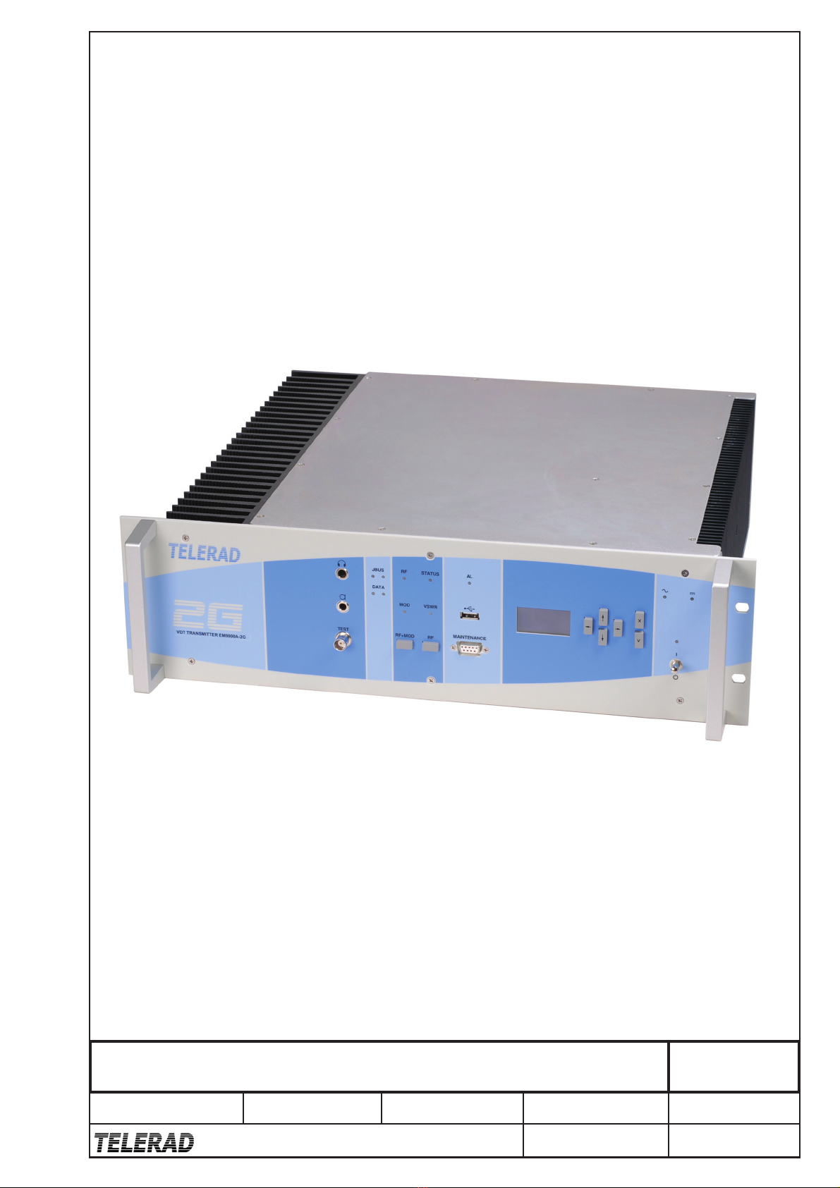
VHF DIGITAL TRANSMITTER
Overall view
Rèf. ens. : EM9000-2G Code ens. : 80000086 Page : 1/1
Rèf. s/ens. : EM9010A-2G Code s/ens. : 84500144
44000312
Indice rév. :V1.00
Date rév. : 02/03/11
TEL : +33 5 59 58 55 00
FAX : +33 5 59 58 55 01
email address
2 Avenue de la butte aux cailles, B.P. 302 64603 ANGLET CEDEX FRANCE
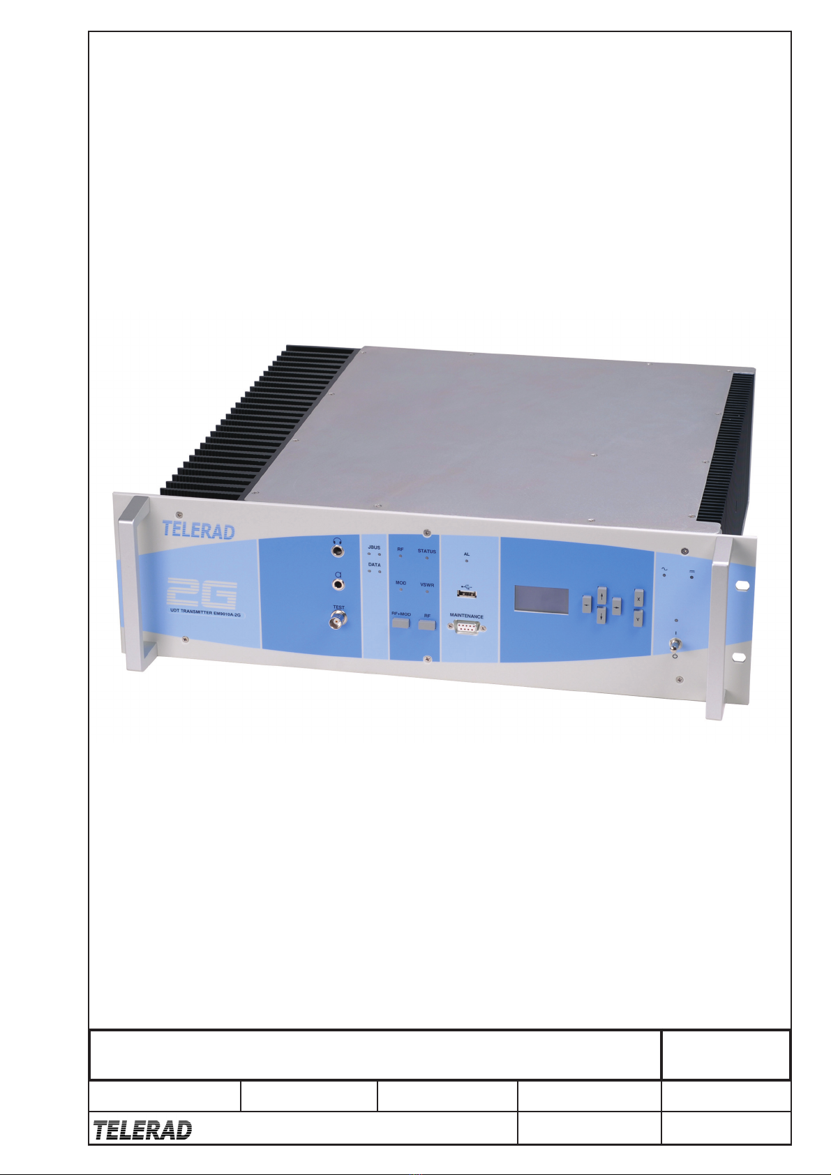
UHF DIGITAL TRANSMITTER
Overall view
Rèf. ens. : EM9010-2G Code ens. : 80300035 Page : 1/1

VHF DIGITAL TRANSMITTER EM9000-2G
UHF DIGITAL TRANSMITTER EM9010-2G
TECHNICAL MANUAL - 40500068 V1.10
43001758 V1.10 A
LIST OF MODIFICATIONS
No. PAGE(S) CORRECTED REVISION DATE SIGNATURE
V1.00 Created on 16/02/11 16/02/11 JPD
V1.01 Updates 17/02/11 JPD
V1.02 Updates 09/03/11 JPD
V1.03 Translation to English and updates. 05/04/11 JPD
V1.04 Pages A to 172. 18/05/11 BP
V1.05 Pages A to 172. 06/06/11 BP
V1.06 §5.9 Procedure for VoIP operation 12/07/11 JPD
V1.07
Adding ref KITGB. Modification of Alarm led management,
Modification of HMI : remark about ETH2, CBIT p2/2, IBIT p1/2 et
2/2. Suppressing § about software release.
17/11/11
24/11/11 JPD
V1.08 8.1.1. AMPV26260 module (52000634). 23/01/12 BP
V1.09 Synthesizerr index F. 20/02/12 JPD
V1.10 Transceiver configurations 1 and 2 : Coaxial relay settings. Sheet
D8 Disassembly/Reassembly of a coaxial relay
11/04/12 JPD
NOTA: Any user who has suggestions for modifying or improving this document is
requested to send their observations to the following address:
Service Documentation Client
2, Avenue de la Butte aux Cailles, BP 302
64603 ANGLET Cedex – France
Telephone: +33 (0) 5 59 58 55 00
Fax: +33 (0) 5 59 58 55 01
e-mail: [email protected]
Website: www.telerad.fr

VHF DIGITAL TRANSMITTER EM9000-2G
UHF DIGITAL TRANSMITTER EM9010-2G
TECHNICAL MANUAL - 40500068 V1.10
B43001758 V1.10
This page is intentionally left blank

VHF DIGITAL TRANSMITTER EM9000-2G
UHF DIGITAL TRANSMITTER EM9010-2G
TECHNICAL MANUAL - 40500068 V1.10
43001758 V1.10 C
CONTENTS
CHAPTER 1.INTRODUCTION .................................................................................................... 1
1.1ABOUT TELERAD ................................................................................................... 1
1.2TARGETED USERS ................................................................................................. 1
1.3ABOUT THIS MANUAL.......................................................................................... 1
1.3.1Manual structure......................................................................................................... 2
1.3.2Conventions used in this manual................................................................................ 2
1.4SAFETY RULES ....................................................................................................... 3
1.4.1Information regarding safety ...................................................................................... 3
1.4.2Symbols used.............................................................................................................. 4
1.4.3Safety instructions ...................................................................................................... 5
1.5TRANSPORT AND STORAGE.............................................................................. 15
1.5.1General information ................................................................................................. 15
1.5.2Packing – Pre-packaging .......................................................................................... 15
1.5.3Packaging ................................................................................................................. 15
1.5.4Transportation .......................................................................................................... 16
1.5.5Storage...................................................................................................................... 16
1.6CONFORMITY........................................................................................................ 16
1.6.1Reference directives ................................................................................................. 16
1.6.2CE certification......................................................................................................... 18
1.6.3Equipment traceability ............................................................................................. 18
1.7WARRANTY........................................................................................................... 19
1.8COPYRIGHT ........................................................................................................... 19
1.9REFERENCE DOCUMENTS ................................................................................. 19
CHAPTER 2.PRESENTATION .................................................................................................. 21
2.1GENERAL ............................................................................................................... 21
2.2PRESENTATION OF THE EQUIPMENT.............................................................. 22
2.2.1Presentation of hardware .......................................................................................... 22
2.2.2Presentation of software ........................................................................................... 23
2.2.3Different versions..................................................................................................... 24
2.2.4Sub-assemblies ......................................................................................................... 24
2.2.5Options ..................................................................................................................... 25
2.2.6Set of mobile plugs................................................................................................... 25
2.2.7Compatible equipment ............................................................................................. 26
2.3EQUIPMENT SPECIFICATIONS .......................................................................... 27
2.3.1Electrical characteristics........................................................................................... 27
2.3.2Mechanical characteristics........................................................................................ 32
2.3.3Climatic and environmental specifications............................................................... 32
CHAPTER 3.OPERATIONAL DESCRIPTION........................................................................ 33
3.1SIMPLIFIED OPERATION .................................................................................... 33
3.1.1Presentation .............................................................................................................. 33
3.1.2Architecture.............................................................................................................. 33
3.1.3Functional description .............................................................................................. 34
CHAPTER 4.PRESENTATION OF EQUIPMENT .................................................................. 37
4.1GENERAL DESCRIPTION .................................................................................... 37
4.1.1Presentation of front panel........................................................................................ 37
4.1.2Presentation of rear panel ......................................................................................... 41
4.2DESCRIPTION OF CONNECTORS ...................................................................... 44
4.2.1Front panel connectors ............................................................................................. 44
4.2.2Rear panel connectors............................................................................................... 45
4.3ELECTRICAL INTERFACES USED ..................................................................... 55

VHF DIGITAL TRANSMITTER EM9000-2G
UHF DIGITAL TRANSMITTER EM9010-2G
TECHNICAL MANUAL - 40500068 V1.10
D43001758 V1.10
CHAPTER 5.INSTALLATION – CONFIGURATION – COMMISSIONING ...................... 59
5.1CHOICE OF SITE.................................................................................................... 59
5.2INSTALLATION..................................................................................................... 59
5.2.1Unpacking ................................................................................................................ 59
5.2.2Electrical protection of the equipment...................................................................... 59
5.2.3Configuration ........................................................................................................... 60
5.2.4Mechanical installation............................................................................................. 60
5.3DESCRIPTION AND CONFIGURATION OF JUMPERS AND SWITCHES...... 61
5.3.1CTRL11217 PCB ..................................................................................................... 61
5.3.2PAVE41160 Front panel PCB.................................................................................. 61
5.3.3MIPR11005 Microcontroller – DSP PCB ................................................................ 62
5.3.4AMPV26260 VHF Amplifier, AMPU26246 UHF Amplifier, SVHF25077 VHF
Synthesizer, SUHF25078 UHF Synthesizer, and ALIM26265 Power supply
Modules.................................................................................................................... 62
5.4ASSEMBLY OF COAXIAL RELAYS ................................................................... 62
5.5MINIMUM CONNECTION FOR COMMISSIONING.......................................... 63
5.6CONNECTION IN TRANSCEIVER CONFIGURATION..................................... 64
5.7BASIC COMMISSIONING..................................................................................... 66
5.8PRELIMINARY ADJUSTMENTS ......................................................................... 67
5.9EQUIPMENT COMMISSIONING IN VoIP CONFIGURATION ......................... 67
5.9.1Connection to a network........................................................................................... 67
5.9.2Configuration of the network parameters................................................................. 68
5.9.3Configuration of the operating mode........................................................................ 68
5.9.4Configuration of the SIP parameters ........................................................................ 68
5.9.5Normal users name listing ........................................................................................ 69
5.9.6High priority users name list .................................................................................... 69
5.9.7Commissioning......................................................................................................... 69
5.10EQUIPMENT COMMISSIONING IN SNMP CONFIGURATION....................... 69
5.10.1Presentation .............................................................................................................. 69
5.10.2SNMP protocol......................................................................................................... 70
5.10.3Parameters to be monitored and controlled .............................................................. 70
5.10.4Equipments configuration ........................................................................................ 71
5.11PROCEDURE FOR SOFTWARE UPLOAD.......................................................... 71
CHAPTER 6.OPERATION.......................................................................................................... 73
6.1PRESENTATION .................................................................................................... 73
6.2COMMANDS AVAILABLE FOR OPERATION................................................... 73
6.2.1Local commands through the screen/keyboard interface ......................................... 73
6.2.2Local commands through the RS232 terminal ......................................................... 74
6.2.3Remote commands through the JBUS link............................................................... 76
6.2.4Remote commands through the SNMP link ............................................................. 77
6.3LOCAL OPERATION OF THE EQUIPMENT ...................................................... 77
6.3.1Local commands through the front panel screen/keyboard interface ....................... 77
6.3.2Local operation through the front panel RS232 interface....................................... 117
6.4REMOTE OPERATION OF EQUIPMENT.......................................................... 118
6.4.1Remote operation through the JBUS link............................................................... 118
6.4.2Remote operation through the SNMP link ............................................................. 118
CHAPTER 7.MAINTENANCE ................................................................................................. 119
7.1MAINTENANCE CONCEPT................................................................................ 119
7.1.1Reminder of safety rules......................................................................................... 119
7.1.2Preventive maintenance.......................................................................................... 119
7.1.3Corrective maintenance.......................................................................................... 119
7.2ELEMENTS FOR MAINTENANCE HELP ......................................................... 120
7.2.1ALIN26270 or ALIN26272 power supply module ................................................ 120
7.2.2CTRL11217 control and management PCB ........................................................... 120

VHF DIGITAL TRANSMITTER EM9000-2G
UHF DIGITAL TRANSMITTER EM9010-2G
TECHNICAL MANUAL - 40500068 V1.10
43001758 V1.10 E
7.2.3MIPR11005 microcontroller and DSP PCB........................................................... 120
7.2.4PAVE41160 front panel PCB................................................................................. 120
7.2.5SVHF25077 or SUHF25078 synthesizer modules ................................................. 120
7.2.6AMPV26260 VHF or AMPU26246 UHF Amplifier modules............................... 120
7.3FAULT LOCALISATION..................................................................................... 121
7.4MAINTENANCE AND CLEANING OPERATIONS .......................................... 121
7.4.1Frequency table ...................................................................................................... 121
7.4.2Maintenance operations directory .......................................................................... 121
7.4.3List of required tools .............................................................................................. 121
7.4.4E1 guide sheet ........................................................................................................ 122
7.5DISASSEMBLY / REASSEMBLY OPERATIONS ............................................. 123
7.5.1Frequency table ...................................................................................................... 123
7.5.2Maintenance operations directory .......................................................................... 123
7.5.3List of required tools .............................................................................................. 123
7.5.4General note regarding disassembly of PCBs or modules...................................... 123
7.5.5D1 guide sheet........................................................................................................ 124
7.5.6D2 guide sheet........................................................................................................ 126
7.5.7D3 guide sheet........................................................................................................ 127
7.5.8D4 guide sheet........................................................................................................ 128
7.5.9D5 guide sheet........................................................................................................ 130
7.5.10D6 guide sheet........................................................................................................ 132
7.5.11D7 guide sheet........................................................................................................ 134
7.5.12D8 guide sheet........................................................................................................ 136
7.6OPERATION CHECKS......................................................................................... 139
7.6.1Frequency table ...................................................................................................... 139
7.6.2Maintenance operations directory .......................................................................... 139
7.6.3List of required measurement devices .................................................................... 139
7.6.4V1 guide sheet........................................................................................................ 140
7.6.5V2 guide sheet........................................................................................................ 141
7.7ADJUSTMENT OPERATIONS ............................................................................ 150
7.7.1Frequency table ...................................................................................................... 150
7.7.2Maintenance operations directory .......................................................................... 150
7.7.3List of required tools .............................................................................................. 150
7.7.4R1 guide sheet ........................................................................................................ 151
7.7.5R2 guide sheet ........................................................................................................ 152
7.7.6R3 guide sheet ........................................................................................................ 154
CHAPTER 8.PARTS LIST......................................................................................................... 159
8.1LEVEL 1 PARTS LIST.......................................................................................... 159
8.1.1EM9000-2G VHF transmitter................................................................................. 159
8.1.2EM9010-2G UHF transmitter................................................................................. 159
CHAPTER 9.DIAGRAMS.......................................................................................................... 161
9.1LIST OF PHOTOS................................................................................................. 161
9.2LIST OF MECHANICAL PLATES ...................................................................... 161
9.3LIST OF INTERCONNECTION PLATES ........................................................... 161
9.4LIST OF BLOCK DIAGRAM PLATES ............................................................... 162
9.5LIST OF LAYOUT VIEW SLIDES ...................................................................... 162
APPENDIX A.LIST OF ABBREVIATIONS.............................................................................. 163
APPENDIX B.R&TTE DECLARATION OF CONFORMITY ............................................... 165
B.1.R&TTE Declaration of conformity for the EM9000A-2G VHF transmitter.......... 165
B.2.R&TTE Declaration of conformity for the EM9010A-2G UHF transmitter.......... 166

VHF DIGITAL TRANSMITTER EM9000-2G
UHF DIGITAL TRANSMITTER EM9010-2G
TECHNICAL MANUAL - 40500068 V1.10
F43001758 V1.10
LIST OF FIGURES
Figure 1– Front panel .......................................................................................................................................... 37
Figure 2 – JACK connector for microphone ......................................................................................................... 40
Figure 3 – JACK connector for headphones.......................................................................................................... 40
Figure 4 - Management of the "ALARM" led....................................................................................................... 40
Figure 5– Rear panel ........................................................................................................................................... 41
Figure 6– Rear panel ........................................................................................................................................... 63
Figure 7– Connection in transceiver configuration 1 .......................................................................................... 64
Figure 8– Connection in transceiver configuration 2 .......................................................................................... 65
Figure 9– Connection in transceiver configuration 3 .......................................................................................... 65

VHF DIGITAL TRANSMITTER EM9000-2G
UHF DIGITAL TRANSMITTER EM9010-2G
TECHNICAL MANUAL - 40500068 V1.10
43001758 V1.10 G
LIST OF SLIDES
LIST OF PHOTOS
TELERAD
code Name Assembly or Sub-
assembly
44000225 ¾ photo of EM9000A-2G VHF transmitter EM9000A-2G
44000226 Front and Rear Photo of EM9000A-2G EM9000A-2G
44000227 Photo from above of EM9000A-2G EM9000A-2G
44000312 ¾ photo of EM9010A-2G UHF transmitter EM9010A-2G
44000314 Front and Rear Photo of EM9010A-2G EM9010A-2G
44000299 Photo from above of EM9010A-2G EM9010A-2G
LIST OF MECHANICAL PLATES
TELERAD
code Name Assembly or Sub-
assembly
45000060 Mechanical dimensions / weight 1/1 EM9000-2G
45000064 Mechanical dimensions / weight 1/1 EM9010-2G
LIST OF INTERCONNECTION PLATES
TELERAD
code Name Assembly or Sub-
assembly
45500036 Uninterruptible power supply interconnection 1/1 ALIN26270/72
45500037 Continuous power supply interconnection 1/1 ALDC26264
45500040 VHF transmitter general interconnection EM9000-2G
45500045 UHF transmitter general interconnection EM9010-2G
LIST OF BLOCK DIAGRAM PLATES
TELERAD
code Name Assembly or Sub-
assembly
46000124 VHF transmitter general diagram 1/1 EM9000-2G
46000125 Uninterruptible power supply module diagram 1/1 ALIN26270/
ALIN26272
46000126 Front panel PCB diagram 1/1 PAVE41160
46000127 VHF amplifier module diagram 1/1 AMPV26260
46000128 Control PCB diagram 1/2 CTRL11217

VHF DIGITAL TRANSMITTER EM9000-2G
UHF DIGITAL TRANSMITTER EM9010-2G
TECHNICAL MANUAL - 40500068 V1.10
H43001758 V1.10
TELERAD
code Name Assembly or Sub-
assembly
46000129 Control PCB diagram 2/2 CTRL11217
46000130 µC/DSP module general diagram 1/1 MIPR11005
46000131 µC/DSP module diagram 1/1 MIPR11005
46000132 VHF synthesizer module diagram 1/1 SVHF25077
46000133 Continuous power supply module diagram 1/1 ALDC26264
46000145 UHF synthesizer module diagram 1/1 SUHF25078
46000147 UHF transmitter general diagram 1/1 EM9010-2G
46000148 UHF amplifier module diagram 1/1 AMPU26246
LIST OF LAYOUT VIEW SLIDES
TELERAD
code Name Assembly or Sub-
assembly
46500142 Synthesizer module layout 1/1 SVHF25077/
SUHF25078
46500150 Control PCB layout 1/1 CTRL11217
46500151 Front panel PCB layout 1/1 PAVE41160
46500155 Side A µC/DSP PCB layout 1/2 MIPR11005
46500156 Side B µC/DSP PCB layout 2/2 MIPR11005
46500178 Side A UHF amplifier module 1/2 AMPU26246
46500179 Side B UHF amplifier module 2/2 AMPU26246
46500180 Side A VHF amplifier module 1/2 AMPV26260
46500181 Side B VHF amplifier module 2/2 AMPV26260
46500195 Continuous power supply module layout 1/1 REAL16102
46500211 Cold plate power supply module layout 1/1 ALPF26271/
ALPF26273
46500212 Uninterruptible power supply module layout 1/1 RALI16105/
RALI16107

VHF DIGITAL TRANSMITTER EM9000-2G
UHF DIGITAL TRANSMITTER EM9010-2G
TECHNICAL MANUAL - 40500068 V1.10
CHAPTER 1
INTRODUCTION
43001758 V1.10 1
CHAPTER 1. INTRODUCTION
1.1 ABOUT TELERAD
With over 40 years’ experience, TELERAD offers a very high quality range of Ground to Air
radiocommunication equipment in the civil (VHF) or military (UHF) frequency range, as well as
associated peripheral equipment. All this equipment is in compliance with the international standards
in force and provides comprehensive, reliable and upgradeable system solutions.
For any additional information, please contact the company at the following address:
2, Avenue de la Butte aux Cailles, BP 302
64603 ANGLET Cedex – France
Telephone: +33 (0) 5 59 58 55 00
Fax: +33 (0) 5 59 58 55 01
e-mail: [email protected]
Website: www.telerad.fr
A hotline may also be made available if required. Please contact the sales department.
1.2 TARGETED USERS
This document is intended for maintenance technicians who wish to install or adjust the equipment,
put it into service and monitor it in operation. It also allows authorised personnel to carry out level 3
operations on the equipment (repairing a sub-assembly, a PCB or a module).
1.3 ABOUT THIS MANUAL
This document is a technical manual. It contains all the required information for the start-up,
operation, preventive and corrective maintenance of the EM9000-2G VHF or EM9010-2G UHF
transmitter.

CHAPTER 1
INTRODUCTION
VHF DIGITAL TRANSMITTER EM9000-2G
UHF DIGITAL TRANSMITTER EM9010-2G
TECHNICAL MANUAL - 40500068 V1.10
243001758 V1.10
1.3.1 Manual structure
This manual is structured as follows:
Chapter 1: Introduction. The first chapter gives a presentation of this document, the
conventions used, the safety and transport instructions, the standards with which it complies,
and traceability and legal information.
Chapter 2: Presentation. Presentation of the EM9000-2G VHF and EM9010-2G UHF
transmitters,the available options, the compatible equipment, and of the electrical, mechanical
and environmental characteristics.
Chapter 3: Operational description. Contains a simplified description of the operation of
EM9000-2G VHF and EM9010-2G UHF transmitters.
Chapter 4: Description of the equipment. Complete description of the EM9000-2G VHF and
EM9010-2G UHF transmitters: front and rear panel and connectors.
Chapter 5: Installation – Configuration – Commissioning. Allows mechanical installation
and commissioning of the EM9000-2G VHF and EM9010-2G UHF transmitters. It also
contains a comprehensive description of the jumpers and switches of the sub-assemblies.
Chapter 6: Operation. Presentation of local or remote operating principles. Details of
hardware and software commands.
Chapter 7: Maintenance. Preventive maintenance, corrective maintenance, locating failures,
operating procedures presented in the form of maintenance, sub-assembly disassembly /
reassembly, verification and adjustment sheets.
Chapter 8: Parts list. List at sub-assembly level of the components of the EM9000-2G VHF
and EM9010-2G UHF transmitters.
Chapter 9: Plates. List of photos, mechanical, interconnection, block diagram and layout plates
provided in the appendix.
Appendix A: Glossary: List of terms, abbreviations and acronyms used in this document.
Appendix B: EC certificate of conformity.
1.3.2 Conventions used in this manual
Indicates a remark giving additional information
Cross-reference to a section in this manual or another document.

VHF DIGITAL TRANSMITTER EM9000-2G
UHF DIGITAL TRANSMITTER EM9010-2G
TECHNICAL MANUAL - 40500068 V1.10
CHAPTER 1
INTRODUCTION
43001758 V1.10 3
1.4 SAFETY RULES
Besides the quality criteria and high performance standards retained by TELERAD in designing its
equipment, the company also gives great importance to user safety by constantly keeping its product
design, manufacturing and test in compliance with the safety standards in force.
As such, the EM9000-2G VHF and EM9010-2G UHF transmitters comply with the current EC
standards. To maintain this level of safety, the user must comply with the safety guidelines described
in this manual before switching on the equipment for the first time. If these rules are not followed or
the equipment is used for a purpose for which it is not designed (incorrect use), TELERAD cannot be
held responsible for risks related to equipment damage or physical injury.
1.4.1 Information regarding safety
The equipment is designed to operate entirely safely when it is installed and used in compliance with
the instructions for use and the general safety rules.
The directives contained in this section explain the potential risks related to use of the equipment, and
provide safety rules intended to reduce these risks.
Scrupulously respecting the information contained in this section and the specific instructions supplied
with the equipment enables you to protect yourself from the risks, and create a safe working
environment.
1.4.1.1 Installation requirements
The equipment operates in a safe manner when it is used according to the fixed electrical magnitudes,
and in compliance with its instructions for use.
1.4.1.2 Servicing
The internal components of the equipment may only be serviced by trained and qualified staff.
Opening or removing covers bearing danger symbols or stickers exposes you to electric shocks.
1.4.1.3 Ventilation
The equipment’s ports and openings are intended for ventilation, and must never be blocked or
covered. They ensure reliable operation of the product and protect it against excessive temperatures.
Allow sufficient air circulation around the equipment, to ensure adequate cooling. Avoid direct
exposure to radiant heat sources.
1.4.1.4 Water and humidity
Do not use the equipment in a humid environment.
CHAP
INTR
O
4
1.4.1
The
t
The
m
This
reco
m
Whe
n
Eart
h
not h
1.4.2
The
expl
a
1.4.2
P
TER 1
O
DUCTIO
N
.5 Prot
e
t
erminal on
t
m
inimum cr
o
connection
m
m
mended to
n
the equip
m
h
ing is a saf
e
ave an earth
Sy
m
following l
i
a
nation. The
y
safety sy
m
operation
a
.1 Safe
Indi
c
This
AT
T
ope
r
para
g
If th
e
of c
e
the
c
carr
y
Indi
c
Indi
c
Indi
c
Indi
c
e
ction throu
g
t
he rear, ide
n
o
ss-section
o
m
ust be ma
d
check the e
a
m
ent has a M
a
e
ty element.
D
connection.
m
bols used
i
st gives th
e
y
are divide
d
m
bols,
a
l symbols.
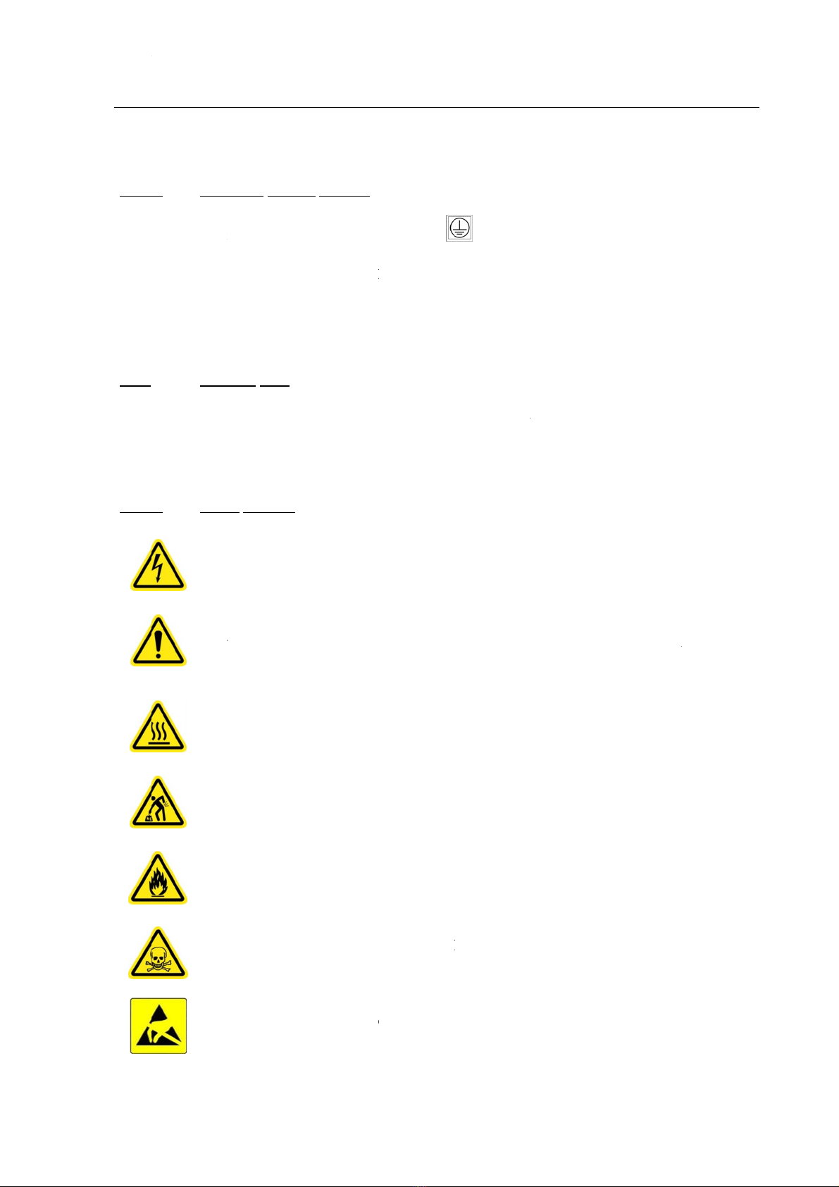
ty symbols
c
ates danger
o
symbol, pr
e
T
ENTION o
r
r
ating phases
g
raph of the
e
fan does n
o
e
rtain comp
o
c
over is rem
o
y
ing out mai
n
c
ates the ris
k
c
ates a risk
o
c
ates danger
c
ates risk of
g
h earthing
n
tified with t
h
o
f the wire u
s
d
e before an
y
a
rth continui
t
a
ins power i
n
D
o not nulli
f
e
symbols
u
d
into two gr
o
o
us voltage.
e
sent both o
n
r
ATTENTI
O
, maintenan
c
instructions
o
t work corr
e
o
nents. The r
i
o
ved. The o
p
n
tenance op
e
k
of physical
o
f fire to the
e
of serious i
n
damage to e
q
h
e symbol
s
ed must be
2
y other con
n
t
y regularly.
n
put, it is fit
t
f
y the prote
c
u
sed in thi
s
o
ups:
n
the equipm
e
O
N DANGE
c
e and repai
r
first.
e
ctly, there i
isk is indica
t
p
erator must
e
rations.
injury duri
n
equipment.
n
jury or deat
h
quipment b
y
VHF
UHF
is the m
a
2
.5 mm².
n
ection, and
t
ed with a t
h
c
tion by con
n
s
manual a
n
e
nt and thro
u
R message.
W
r
phases, car
e
s a risk of a
s
t
ed by an att
a
wait for the
n
g equipmen
t
h
.
y
electrostati
c
DIGITAL T
R
DIGITAL T
R
TECHNICA
L
a
in protectiv
e
must be dis
c
r
ee-pin plug
n
ecting the
p
n
d the equi
p
u
ghout the i
n
W
hen this s
y
e
fully read t
h
s
ignificant i
n
a
ched sticke
r
e
quipment t
o
t
handling d
u
c
discharge
(
R
ANSMITTE
R
R
ANSMITTE
R
L
MANUAL - 4
0
e
earth termi
connected l
a
g
with an ear
t
p
lug to a soc
k
p
ment, alon
g
n
structions,
g
y
mbol is pre
s
h
e correspo
n
n
crease in th
r
that can be
o
cool down
u
e to its hea
v
(
ESD).
R
EM9000-2G
R
EM9010-2G
0
500068 V1.10
43001758 V1.1
0
n
al.
a
st. It is als
o
t
h.
k
et that doe
s
g
with thei
r
g
ives an
s
ent during
n
ding
e temperatu
r
seen when
before
v
y weight.
0
o
s
r
r
e
VHF
D
UHF
D
TECH
N
43001
7
1.4.2
1.4.3
1.4.3
The
f
and
r
cons
t
equi
p
TEL
E
The
p
redu
c
D
IGITAL TR
A
D
IGITAL TR
A
N
ICAL MANUA
7
58 V1.1
0
.2 Ope
r
Indic
a
termi
n
Indic
a
termi
n
Indic
a
Indic
a
Indic
a
Indic
a
Indic
a
Indic
a
This s
must
b
The
m
It is a
l
Saf
e
.1 Gen
e
f
ollowing g
e
r
epair phase
s
t
itutes a vio
p
ment.
E
RAD may
n
p
urpose of
c
e the risk o
f
A
NSMITTER
A
NSMITTER
L - 40500068
V
r
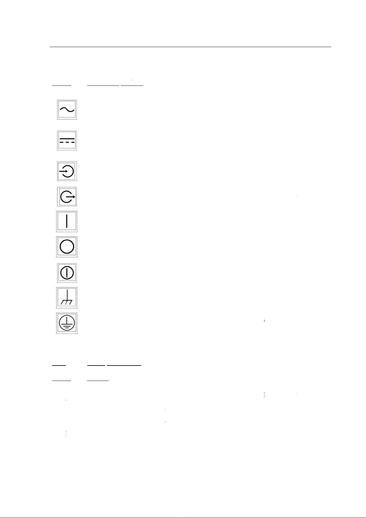
ational sym
b
a
tes that the
e
n
al.
a
tes that the
n
al.
a
tes an input
a
tes an outp
u
a
tes that the
e
a
tes that the
e
a
tes that the
e
a
tes the equi
p
ymbol indic
b
e made bef
o
m
inimum cro
s
l
so recomm
e
e
ty instructi
o
e
ral
e
neral safet
y
s
. Failure to
r
lation of th
n
ot be held
r
reading an
d
f
injury.
EM9000-2G
EM9010-2G
V
1.10
b
ols
e
quipment
m
equipment
terminal wh
e
u
t terminal w
h
e
quipment p
o
e
quipment p
o
e
quipment p
o
p
ment termi
n
a
tes an eart
h
o
re any othe
r
s
s-section o
f
nded to che
c
o
ns
y
precaution
s
r
espect thes
e
e
safety sta
n
esponsible f
o
d
respecting
m
ust be sup
p
must be s
u
en distinctio
h
en distincti
o
wer supply
o
wer supply
o
wer supply
n
al connecte
d
h
ed connecti
o
r
connection
,
f
the earth w
i
c
k the earth
c
s
must be r
e
e
precaution
s
n
dards appl
i
fo
r the user’s
the recom
m
p
lied with al
t
u
pplied with
n between i
n
on between
i
is On.
is Off.
is On/Off.
d
to ground
o
o
n. This co
n
,
and must b
e
i
re must be
2
c
ontinuity re
e
spected dur
i
s
or any oth
e
i
ed to the
d
failure to re
m
endations
c
t
ernating cu
r
direct curr
e
n
puts and ou
t
i
nputs and o
u
o
r chassis.
n
ection is t
h
e
disconnect
e
2
.5mm².
g
ularly.
i
ng the equi
p
e
r warning p
r
d
esign, man
u
s
pect these i
n
c
ontained in
IN
T
r
rent (AC) a
t
e
nt (DC) at
t
puts is requ
u
tputs is req
u
h
e main prot
e
t
ed last.
pment use,
m
resent in th
e
u
facture an
d
nstructions.
these instr
u
CHAPTER 1
T
RODUCTIO
N
5
t
the indicat
e
the indicat
e
i
red.
u
ired.
e
ctive earth.
m
aintenanc
e
e
instruction
s
d
use of th
e
u
ctions is t
o
5
e
d
e
d
It
e
s
e
o

CHAP
INTR
O
6
1.4.3
High
volta
g
time
s
It i
s
This
equi
p
secti
o
In p
a
conn
e
conn
e
to th
e
Sele
c
coun
t
An u
n
Befo
r
corre
If ba
t
Com
p
envi
r
P
TER 1
O
DUCTIO
N
.2 Elec
voltages ar
g
e of 110V
s
:
unplug th
e
be wary o
f
unplug po
w
of the hard
w
understan
d
reached in
t
discharge
removed fr
s
prohibit
e
N
c
equipment
m
p
ment chass
i
o
n of 2.5m
m
a
rticular, w
h
e
cted to th
e
e
cted first a
n
e
default cur
r
c
t a power s
u
t
ry in which
n
suitable co
r
damage to
the equip
m
r
e powerin
g
spond to th
o
t
teries are u
p
ly with t
h
r
onmental st
a
trical risks
e required
w
may cause
d
e
energy sou
r
f
electrical s
a
w
er supplies
w
are,
d
that safet
y
t
he event of
capacitors.
D
om service.
e
d to enter
a
N
OTA :
D
o
ause death.
m
ay have a
s
i
s must be
c
m
² using the
a
h
en the equ
i
e
rack chas
s
n
d disconne
c
r
ent.
u
pply cord t
h
the equipm
e
r
d may resul
t
the device d
u
m
ent catchin
g
g
on the d
e
o
se values re
c
sed, they m
u
h
eir technic
a
ndards in f
o
PRESE
N
w
hen using
t
d
eath. Perso
n
r
ce before c
h
a
fety device
s
, both exter
n
y
devices ar
e
disassembl
y
D
angerous
v
a
room alo
hi
g
not be fool
e
EA
R
s
ignificant e
a
c
onnected t
o
a
ppropriate
m
i
pment is i
n
s
is, which
s
c
ted last, and
POWER S
U
h
at offers all
e
nt is used, a
n
t
in either:
u
e to electri
c
g
fire.
POW
E
e
vice, chec
k
c
ommended
u
st not be e
x
a
l characte
r
o
rce during r
e
N
CE OF HI
G
t
his equipm
e
nnel must f
o
h
anging an e
l
s
(e.g. circui
t
n
al and inter
n
e
designed f
o
y
,
v
oltages ma
y
ne to carr
y
g
h-risk eq
u
e
d by the ter
m
R
TH CON
N
a
rth leakage
o
earth, by
a
m
arked termi
n
stalled in
a
s
hall itself
b
d
must be co
n
U
PPLY C
O
l
safety guar
a
n
d which is
s
c
al discharg
e
E
R SUPPL
Y
k
that the
p
by TELER
A
xposed to e
x
r
istics, as
w
e
cycling.
VHF
UHF
G
H VOLT
A
e
nt. These
a
o
llow all of
l
ectrical co
m
t
breakers, d
r
n
al (batterie
s
o
r standard
o
y
remain in
y
out inspe
c
u
ipment.
m
"Low Vol
N
ECTION
current. To
a
low impe
d
nal .
a
rack, che
c
b
e connect
e
n
nected to a
c
O
RD SELE
C
a
ntees accor
d
s
uited to the
e
s, o
r
Y
VOLTAG
E
p
ower supp
A
D (refer to
t
x
treme tem
p
w
ell as th
e
DIGITAL T
R
DIGITAL T
R
TECHNICA
L
A
GE
a
re dangero
u
the followi
n
m
ponent,
r
awer and d
o
s
) to perfor
m
o
penings. D
a
the capacit
o
c
tions or
m
t
age" (LV).
5
r
educe the r
i
d
ance cord,
c
k that its
e
d to earth.
c
onductor w
i
C
TION
d
ing to the l
e
equipment i
E
S
ly voltages
,
t
he characte
r
p
eratures. D
o
ir expiry
d
R
ANSMITTE
R
R
ANSMITTE
R
L
MANUAL - 4
0
u
s voltages,
n
g safety m
e
o
or devices),
m
operations
o
a
ngerous cir
c
o
rs after the
m
aintenanc
e
5
0 volts are
i
sk of electr
i
with a min
i
e
arth termin
a
This termi
n
w
ith a cross-s
e
l
egislation i
n
i
n terms of c
u
,
mains an
d
r
istics sectio
n
o
not short
c
d
ate. Comp
l
R
EM9000-2G
R
EM9010-2G
0
500068 V1.10
43001758 V1.1
0
given that
a
e
asures at al
l
o
n the insid
e
c
uits may b
e
hardware i
s
e
work on
sufficient t
o
i
c shock, th
e
i
mum cross
-
a
l is indee
d
n
al must b
e
e
ction suite
d
n
force in th
e
u
rrent.
d
/or battery
,
n
).
c
ircuit them
.
l
y with th
e
0
a
l
e
e
s
o
e
-
d
e
d
e
,
.
e

VHF DIGITAL TRANSMITTER EM9000-2G
UHF DIGITAL TRANSMITTER EM9010-2G
TECHNICAL MANUAL - 40500068 V1.10
CHAPTER 1
INTRODUCTION
43001758 V1.10 7
PROTECTION AGAINST LIQUIDS
In order to avoid any risk of short-circuit, fire or any other internal damage, do not spill any liquids
inside the device, and protect it from rain and from contact with liquids of any kind.
PROTECTION AGAINST METAL OBJETS
Do not insert any metal conductors into the equipment.
PROTECTION AGAINST DAMAGED CABLES OR PLUGS
Do not use damaged cables or plugs.
PRESENCE OF AN ON/OFF SWITCH
If the device is not fitted with a mains On/Off switch, the mains cord may be considered a circuit
breaker. In this case it must be easy to access and disconnect.
If there is a mains On/Off switch but access to it is impractical, or when the device’s mains plug is
fitted with a locking clamp, it is essential to add a circuit breaker in the power supply circuit, which
can be easily accessed by the user. If the equipment is used in a Main / Stand-by type configuration,
each item of equipment must have an independent circuit breaker.
PROTECTION FROM THE ELECTRICITY NETWORK
The electricity network powering the equipment must be protected against voltage surges (network
variation), including those related to weather conditions (storms, lightning, etc.)
If there is no such protection, this may result in damage to the equipment, destruction or a fire.
PROTECTION AGAINST RF RADIATION
If using TELERAD transmitter-type equipment, and in order to avoid any risk of burns by RF
radiation or by the presence of high RF voltage when the device is transmitting:
do not unplug the antenna cable.
do not touch the Antenna output connector.
The antenna cable must be connected or disconnected with the equipment powered off.
PROTECTION OF MAINTENANCE STAFF
Unless otherwise specified by TELERAD, the equipment must be powered off before any operations,
with the power cord disconnected. Only certified, qualified and trained staff may open, adjust and
replace the PCBs or equipment modules.
Under certain conditions, dangerous voltages may remain even when the power cord is disconnected.
In order to avoid injury, always disconnect and discharge the circuits before touching them.
When replacing a defective part, refer to the removal/reassembly sheets of this manual,
as well as the adjustment sheets and verification sheets for the smooth functioning of
the equipment (refer to CHAPTER 7 “MAINTENANCE”).
Do not undertake repair or internal adjustment without the presence of another person capable of
administering first aid resuscitation.
Due to the risk of creating additional dangers, do not use substitute parts and do not make any
unauthorised modification to the equipment. When spare parts are required, ensure that the
maintenance staff use the spare parts specified in the maintenance manual and/or in the illustrated
catalogue.

CHAP
INTR
O
8
In e
v
imm
e
Only
to pr
o
The
c
asse
m
the b
r
To a
v
phys
i
Do n
b
efo
r
To d
i
surfa
c
Onc
e
b
efo
r
Use
t
The
r
insta
l
Ever
y
You
m
Gen
e
b
reat
h
First
1s
A
n
ci
r
S
w
or
If
t
1) p
r
cl
2)
m
t
h
a
n
3)
m
2
n
C
h
L
a
A
e.
g
I
f
P
TER 1
O
DUCTIO
N
v
ent of the
e
e
diately swit
people who
o
duce dange
r
P
R
c
ertified sta
f
m
blies must
b
r
acelet cord.
v
oid the risk
i
cal contact
w
ot remove a
n
r
e being rea
d
ivide the st
a
c
e with one
h
e
the electro
n
r
e it is instal
l
t
he electroni
c
r
ules for firs
t
l
ling, operat
i
y
one mus
t
be
m
ust always
e
rally, an el
e
h
ing.
aid involves
taction: P
R
n
alyse the
e
r
cuit is cut.
w
itch off th
e
t
he rescuer
c
r
otect thems
e
oth) and sta
n
m
ove the vict
i
h
e electric ci
r
n
d water are
m
ark out the
a
n
daction: E
X
h
eck for co
n
a
y the victi
m
sk simple q
u
g
. "Can you
f
the victim
r
e
quipment
fa
ch off the e
q
are qualifie
d
r
ous energy
R
OTECTIO
f
f replacing
b
e equipped
of damage l
w
ith the con
n
n
electronic
d
y to install i
t
a
tic electrici
t
h
and and ho
l
n
ic circuit is
l
ed in the eq
u
c
circuit’s p
r
t
aid are bot
h
i
ng or maint
a
e
ready to gi
v
remain cal
m
e
ctric shock
protecting,
e
R
OTECT
e
nvironment
.
e
current.
c
annot switc
h
e
lves: prote
c
n
d on an ins
u
i
m away: us
r
cuit. In par
t
electrical co
n
a
rea to avoid
X
AMINE
n
sciousness
a
m
on their ba
c
u
estions and
h
hear me? If
r
esponds, t
h
fa
lling or su
s
q
uipment an
d
d
and traine
d
levels must
i
N AGAINS
the PCB o
r
with an ant
i
i
nked to ele
c
n
ector pins.
circuit that
i
t
,
t
y between
t
l
d the electr
o
removed fr
o
u
ipment or p
r
otective pac
k
ELECT
R
h
theoretical
a
ining this r
a
v
e first aid t
o
m
.
does not k
i
e
xamining,
a
.
If the vict
i
h
off the cur
r
ct
their han
d
u
lator (e.g.
w
e
a dry non-
t
icular, mov
e
n
ductors,
further com
p
a
nd breathin
g
c
k.
h
old the vic
t
y
ou can hea
r
h
ey are cons
c
s
taining da
m
d
unplug the
d
to maintai
n
i
nstall acces
s
T ELECT
R
r
module o
r
i
static brace
l
c
trostatic dis
is sensitive
t
t
he work s
u
o
nic circuit
w
o
m its prote
c
p
ut back in it
s
k
aging as a
n
R
IC SHOC
and practic
a
a
dio equipm
e
o
avoid any
l
i
ll instantly;
a
lerting and
r
i
m is at a
h
r
ent, they m
u
d
s with a d
r
w
ooden or pl
a
-
conducting
p
e the victi
m
m
plications o
f
g
before givi
n
t
im’s hands.
r
me, squee
z
c
ious and br
e
VHF
UHF
m
age, of un
u
power cord.
n
equipment
s
ories in saf
e
R
OSTATIC
r
performin
g
l
et on one w
r
charges, it i
s
t
o static ele
c
rface and t
h
w
ith the othe
c
tive packag
i
s
protective
p
n
assembly s
u
K: FIRST
A
a
l. These rul
e
e
nt.
l
oss of hum
a
the victim
m
r
escuing.
h
eight, antic
i
u
st:
r
y non-con
d
a
stic stool),
p
ole to rem
o
away from
f
the acciden
t
n
g the alert.
Check that
t
z
e my hands!
e
athing (cas
e
DIGITAL T
R
DIGITAL T
R
TECHNICA
L
u
sual smells
,
and trained
t
e
ty locking
z
D
ISCHAR
G
g
any other
r
ist, connect
e
s
strongly re
c
c
tricity from
h
e electronic
r
hand,
i
ng, do not
p
p
ackaging,
u
rface.
A
ID
e
s concern a
l
a
n life.
m
ay be sav
e
i
pate their
fa
u
cting mate
r
o
ve the victi
m
any metal
o
t
.
h
e victim is
".
1).
R
ANSMITTE
R
R
ANSMITTE
R
L
MANUAL - 4
0
, smoke or
to handle pr
o
z
ones.
G
E (ESD)
operation o
n
t
ed to an ear
t
c
ommended
its protecti
v
circuit, to
u
p
ut it down
o
a
ll staff: whe
t
e
d, even if
t
f
alling when
e
rial (e.g. ru
b
m
from any
o
r damp ele
m
conscious.
R
EM9000-2G
R
EM9010-2G
0
500068 V1.10
43001758 V1.1
0
overheating
,
o
ducts liabl
e
n
these sub
-
t
h socket vi
a
to avoid an
y
v
e packagin
g
ch the wor
k
o
r let go of i
t
t
her they ar
e
t
hey are no
t
the electri
c
b
ber gloves
,
contact wit
h
m
ents. Meta
l
0
,
e
-
a
y
g
k
t
e
t
c
,
h
l

VHF
D
UHF
D
TECH
N
43001
7
or
If
t
A
f
3
r
Di
a
G
t
h
t
h
t
h
D
F
D
4t
h
C
w
C
p
l
t
h
it
D
IGITAL TR
A
D
IGITAL TR
A
N
ICAL MANUA
7
58 V1.1
0
t
he victim
d
f
ter this exa
m
the victim
i
the victim
i
r
daction: R
A
a
l the emer
g
G
ive the foll
o
h
e precise lo
c
h
e number o
f
h
e condition
D
o not hang
u
acilitate the
D
ebrief the e
m
h
action: G
I
ase 1: the vi
ait for the e
m
ase 2: the vi
l
ace the victi
m
h
e recovery
p
helps preve
n
A
NSMITTER
A
NSMITTER
L - 40500068
V
d
oes not res
p
m
ination, the
i
s unconscio
i
s unconscio
A
ISE THE
A
g
ency teleph
o
Fo
r
o
wing infor
m
c
ation: addr
e
f
victims
of the victi
m
u
p first.
arrival of th
e
m
ergency se
r
I
VE FIRST
ctim respon
d
m
ergency se
r
ctim does n
o
m
on their s
i
p
osition is us
n
t the victim
EM9000-2G
EM9010-2G
V
1.10
p
ond, they a
r
loosen th
e
carefully
t
to do so,
fingers o
f
b
ackwar
d
open the
m
the fore
h
b
reathing
put your
e
they are
b
hold this
p
rescuer kno
w
us and breat
h
us and not b
r
A
LERT or
H
o
ne number:
r
France:
m
ation:
e
ss, building
,
m
(s) (e.g. un
c
e
emergenc
y
r
vices when
A
ID
d
s and is bre
a
r
vices.
o
t respond a
n
i
de in the re
c
e
d in the ev
e
from choki
n
r
e unconsci
o
e
ir clothing
(
tip the head
place a ha
n
f
the other h
a
d
s,
m
outh and l
o
h
ead, remo
v
,
e
ar and che
e
b
reathing. W
p
osition for
a
w
s that eith
e
h
ing (case 2
)
reathing (ca
s
H
AVE SO
M
, floor, corri
d
c
onscious pe
y
services as
they arrive.
athing:
n
d is breathi
n
c
overy posit
i
e
nt of a fall
o
n
g due to ob
s
o
us. You mu
s
(
collar, tie, b
back to clea
r
n
d on the f
o
a
nd placed u
n
o
ok inside t
o
v
e anything
e
k close to t
h
atch for the
s
a
pproximat
e
e
r:
)
, or
s
e 3).
M
EONE RA
I
15 Em
e
18 Fire
15 Em
e
d
or, room,
rson, not br
e
close as pos
s
n
g:
on (see belo
w
o
r injury,
s
truction of
t
s
t check thei
r
elt),
r
the airway
s
o
rehead, wit
h
n
der the chi
n
inspect it;
w
that is lia
b
h
e victim’s
n
s
tomach and
/
ly 6 to 10 se
I
SE THE A
L
e
rgency Me
d
brigade
e
rgency call
f
e
athing, etc.)
s
ible to the
v
w
).
h
e tongue o
r
IN
T
r breathing:
s
,
t
h the index
n
, pushing t
o
w
ith the han
d
a
ble to cau
s
n
ose and mo
u
d
/or chest ex
p
e
conds.
LERT
d
ical Service
s
from a mobi
.
v
ictim.
r
regurgitati
o
CHAPTER 1
T
RODUCTIO
N
9
and middl
e
o
tip the hea
d
d
that was o
n
s
e problem
s
u
th to feel i
f
p
anding,
s
le phone
o
ns.
9
e
d
n
s
f
This manual suits for next models
1
Table of contents


