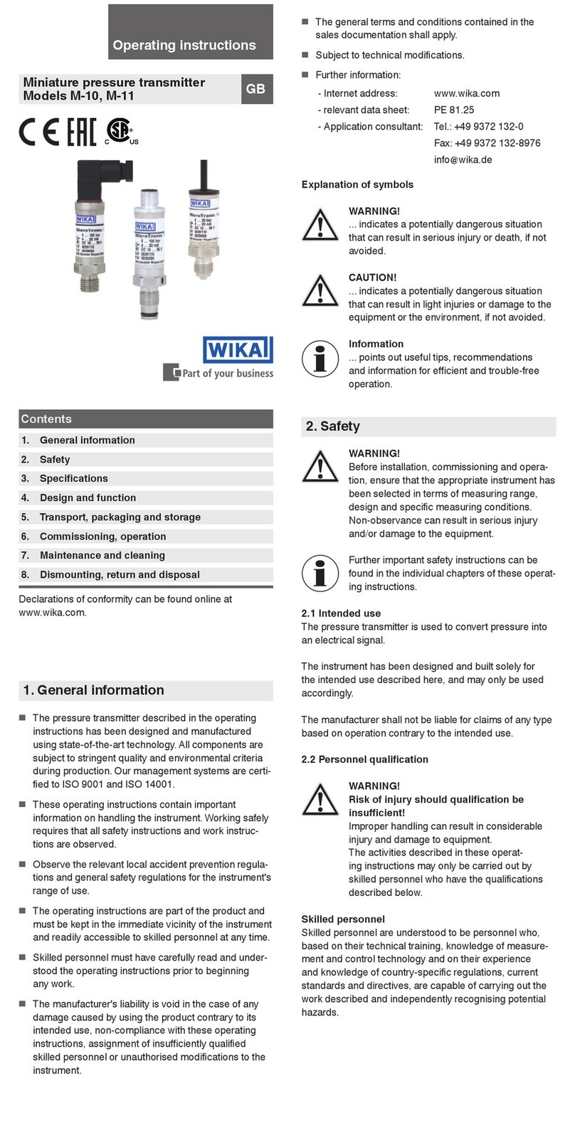
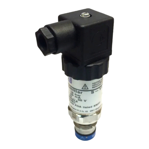
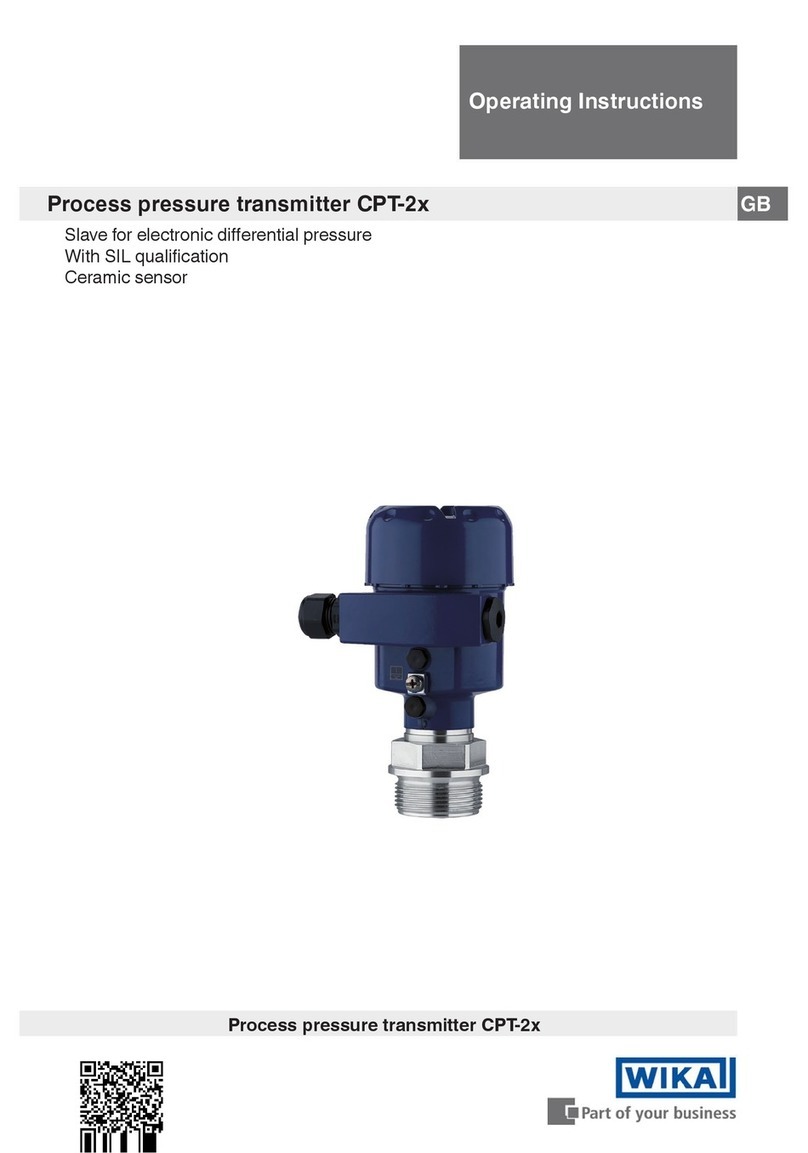
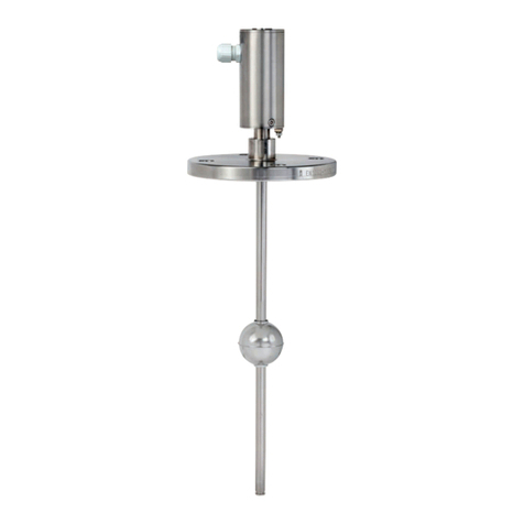
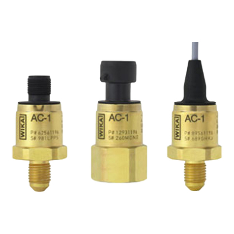
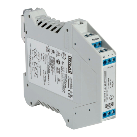
WIKA ls-10 User manual

Level probe /
Pegelsonde /
Sonde de niveau
Operating instructions
Betriebsanleitung
Mode demploi
LS-10, LH-10
IKA Alexander iegand GmbH & Co. KG
Alexander-Wiegand-Straße 30
63911 Klingenberg/Germany
Phone ( 49) 93 72/132-295
Fax ( 49) 93 72/132-706
E-Mail [email protected]
www.wika.de
2121468.06 GB/D/F 01/2006
LH-10LS-10

2121468.06 GB/D/F 01/2006
3WIKA Operating instructions / Betriebsanleitung / Mode d'emploi LS-10, LH-10
2121468.06 GB/D/F 01/2006
2WIKA Operating instructions / Betriebsanleitung / Mode d'emploi LS-10, LH-10
1. Important details for your information / 2. A quick overview GB
Use of the product in accordance with the intended use LS-10, LH-10
Use the level probe for hydrostatic pressure measurement.
1. Important details for your information
Read these operating instructions before installing and starting the pressure transmitter. Keep
the operating instructions in a place that is accessible to all users at any time.
The following installation and operating instructions have been compiled by us with great care
but it is not feasible to take all possible applications into consideration. These installation and
operation instructions should meet the needs of most pressure measurement applications. If
questions remain regarding a specific application, you can obtain further information (data
sheets, instructions, etc.) via our Internet address (www.wika.de / www.wika.com ) or contact
WIKA for additional technical support (see section7 Starting, Operation/Further information).
With special model number e.g. LS-10000 or LH-11000 please note specifications in the
delivery note. The product data sheet is designated as PE 81.09
WIKA pressure transmitters are carefully designed and manufactured using state-of-the-art
technology. Every component undergoes strict quality inspection before assembly and each
instrument is fully tested prior to shipment.
Knowledge required: Install and start the pressure transmitter only if you are familiar with the
relevant regulations and directives of your country and if you have the qualification required.
You have to be acquainted with the rules and regulations on measurement and control
technology and electric circuits, since this pressure transmitter is electrical equipment as
defined by EN 50178. Depending on the operating conditions of your application you have to
have the corresponding knowledge, e.g. of aggressive media.
2. A quick overview for you
If you want to get a quick overview, read Chapters 3, 5, 7 and 10. There you will get some
short safety instructions and important information on your product and its starting. Read
these chapters in any case. Get some more detailed information on this product in Chapters
4 Function and accessories and 6 Packaging. Read Chapter 8 for Maintenance. In the
case of failures please refer to Chapter 9.
1. Important details for your information
2. A quick overview for you
3. Abbreviations, signs and symbols
4. Function and accessories
5. For your safety
6. Packaging
7. Starting, operation
8. Maintenance, spare parts
9. Trouble shooting
10. Storage, disposal
Contents Page 3-13
Inhalt Seite 13-23
1. Informations inportantes
2. Aperçu rapide
3. Explication des symboles,abréviations
4. Fonction et accessoires
5. Pour votre sécurité
6. Emballage
7. Mise en service, exploitation
8. Entretien, Pièces de rechange
9. Elimination de perturbations
10. Stockage, mise au rebus
Contenu Page 24-35
1. ichtiges zu Ihrer Information
2. Der schnelle Überblick für Sie
3. Zeichenerklärungen, Abkürzungen
4. Funktion und Zubehör
5. Zu Ihrer Sicherheit
6. Verpackung
7. Inbetriebnahme, Betrieb
8. artung, Ersatzteile
9. Störbeseitigung
10. Lagerung, Entsorgung
Contents/Inhalt/Contenu
IKA Global Page / Seite / Page 36
F
DGB
Contents / Inhalt / Contenu FDGB
Current terms and conditions apply.
Details are available on ...
Es gelten unsere aktuellen Verkaufs- und
Lieferbedingungen siehe unter ...
Toute commande est assujettie à nos
conditions de ventes et de fournitures dans
leur dernière version en vigueur, voir sous ...
... www.wika.de
F
GB
D

2121468.06 GB/D/F 01/2006
5WIKA Operating instructions / Betriebsanleitung / Mode d'emploi LS-10, LH-10
2121468.06 GB/D/F 01/2006
4WIKA Operating instructions / Betriebsanleitung / Mode d'emploi LS-10, LH-10
Order-No.
71 93 131 The optional filter element for self-mounting avoids the ingress of
pollution and water into the venting tube for the pressure
compensation to the atmosphere.
24 59 686 The optional cable box with weather protection IP 67 with
venting element (NEMA 4) is suitable for mounting outside
of the shafts and tanks or directly in dry control boxes.
For mechanical assembly of the level probe a cable straining
20 74 257 clamp is optionally available.
In order to increase the weight of the level probe an additional
15 24 399 weight (approx. 500 g = 1.1 lb.) can be screwed on.
4. Function and accessories GB
3. Abbreviations, signs and symbols / 4. Function and accessories GB
Power supply Load (e.g. display)
4. Function and accessories
LS-10: Submersible pressure transmitter for level measurement, standard version.
LH-10: Submersible pressure transmitter for level measurement, High Performance.
2-wire Two connection lines are intended for the voltage supply.
The supply current is the measurement signal.
3-wire Two connection lines are intended for the voltage supply.
One connection line is intended for the measurement signal.
4-wire Two connection line are intended for the voltage supply.
Two connection line are intended for the measurement signal.
UB /Sig Positive supply / measurement connection
OV/Sig- Negative supply / measurement connection
The product complies with the
applicable European directives.
Function: With the level probe you measure the hydrostatic pressure of your application,
which is trans-formed into an electric signal. This electric signal changes in proportion to the
hydrostatic pressure and can be evaluated correspondingly.
The product was tested and
certified by CSA International.
It complies with the applicable
Canadien standards on safety.
Accessories: For details about the accessories, please refer to WIKAs price list, WIKAs
product catalog on CD or WIKAs web site www.wika.de.
arning
Potential danger of life or of
severe injuries.
3. Abbreviations, signs and symbols
!
Notice, important information,
malfunction.

2121468.06 GB/D/F 01/2006
7WIKA Operating instructions / Betriebsanleitung / Mode d'emploi LS-10, LH-10
2121468.06 GB/D/F 01/2006
6WIKA Operating instructions / Betriebsanleitung / Mode d'emploi LS-10, LH-10
7. Starting, operation GB
Diaphragm test for your safety
It is necessary that before starting the pressure transmitter you test the diaphragm, as this is
a safety-relevant component.
nPay attention to any liquid leaking out, for this points to a diaphragm damage.
nCheck the diaphragm visually for any damage.
nUse the pressure transmitter only if the diaphragm is undamaged.
nUse the pressure transmitter only if it is in a faultless condition as far as the
safety-relevant features are concerned.
arning
!
Product label (example)
Coded manufacture date
S #
: Signal
: Power Supply
: Serial No.
: Product No.
P #
PIN assignment
→
(A)
←
(B)
InstallationnAn additional strain relief is not necessary because the cable has a max.
tensile strength of 1000 N (500 N with FEP).
nThe protection cap (A) protects the secluded diaphragm (B) from damaging
the level probe duringtransport and immersion. Remove the protection cap if
used with viscous or contaminated media.
nThere must be no differences in potential between medium/tank and the
grounding of the junction box and the control cabinet when the shield of the
cable is applied.
nSelect the appropriate pressure transmitter with regard to scale range,
performance and specific measurement conditions prior to installing and
starting the instrument.
nObserve the relevant national regulations (e.g.: EN 50178) and observe the
applicable standards and directives for special applications.
If you do not observe the appropriate regulations, serious injuries and/or
damage can occur!
nPlease make sure that the pressure transmitter is only used within the overload
threshold limit all the time!
nObserve the ambient and working conditions outlined in section 7 Technical data.
nEnsure that the pressure transmitter is only operated in accordance with the provisions
i.e. as described in the following instructions.
nDo not interfere with or change the pressure transmitter in any other way than
described in these operating instructions.
nRemove the pressure transmitter from service and mark it to prevent it from being used
again accidentally, if it becomes damaged or unsafe for operation.
nTake precautions with regard to remaining media in removed pressure
transmitter. Remaining media in the pressure port may be hazardous or toxic!
nHave repairs performed by the manufacturer only.
5. For your safety
arning
!
Information about material consistency against corrosion and diffusion can be found in our
WIKA-Handbook, 'Pressure and Temperature Measurement'.
6. Packaging
7. Starting, operation
Has everything been supplied?
5. For your safety / 6. Packaging / 7. Starting, operation GB
nInspect the pressure transmitter for possible damage during transportation.
Should there be any obvious damage, inform the transport company and WIKA
without delay.
nKeep the packaging, as it offers optimal protection during transportation
(e.g. changing installation location, shipment for repair).
n Completely assembled level probe

2121468.06 GB/D/F 01/2006
9WIKA Operating instructions / Betriebsanleitung / Mode d'emploi LS-10, LH-10
2121468.06 GB/D/F 01/2006
8WIKA Operating instructions / Betriebsanleitung / Mode d'emploi LS-10, LH-10
7. Starting, operation GB
Specifications Model LS-10, LH-10
Pressure ranges Ø
model LS-10 / bar 1) 0.25 0.4 0.6 1 1.6 2.5 4 6 10
Ø{LH-10 with FEP cable}
Over pressure safety bar 1) 2 2 4 5 10 10 10 10 10
Burst pressure bar 1) 2.4 2.4 4.8 6 12 12 12 12 12
Pressure ranges Ø model LH-10 bar 1) 0.1 0.16 0.25 0.4 0.6 1 1.6 2.5 4 6 10 16 25
with PUR cable
Over pressure safety bar 1) 1 1.5 2 2 4 5 10 10 17 35 35 35 35
Burst pressure bar 1) 2 2 2.4 2.4 4.8 6 12 12 20.5 42 42 42 42
1) 1 bar = 10.2 mH2O
Model LS-10 Model LH-10
Materials
nWetted parts Stainless steel Stainless steel {Hastelloy}
nPressure connection/diaphragm Stainless steel Stainless steel {Hastelloy}
nProtection cap PA PA {stainless steel} {Hastelloy}
nCable PUR PUR {FEP}
Power supply UBUBin DC V 10 < UB≤30 10 < UB≤30
(14 ... 30 with signal output
0 ... 10 V)
(5 ... 30 with battery operation,
signal output 0.5 ... 4.5 V)
Signal output 4 ... 20 mA, 2-wire 4 ... 20 mA, 2-wire
0 ... 20 mA, 3-wire
{0 ... 5 V, 3-wire}
{0 ... 10 V, 3-wire}
{0.5 ... 4.5 V, 3-wire, with
battery operation} 2)
{Pt 100, 4-wire; IEC 60751}
2) For pressure ranges > 0 ... 0.25 bar.
Pt 100 Øonly model LH-10
nI max mA 3
nI meas mA 1
iring
Ingress protection IP 68 per IEC 60529.
Please make sure that the ends of cables with flying leads do not allow any ingress of
moisture.
2-wire
brown
green
blue
screen
brown
blue
screen
green
white
3-wire
Vented PUR-cable tensile
strength 1000 N
(500 N with FEP-cable)
Pt 100-element
grey
red
black
yellow
4-wire

2121468.06 GB/D/F 01/2006
11WIKA Operating instructions / Betriebsanleitung / Mode d'emploi LS-10, LH-10
2121468.06 GB/D/F 01/2006
10 WIKA Operating instructions / Betriebsanleitung / Mode d'emploi LS-10, LH-10
7. Starting, operation / 8. Maintenance, spare parts / 9. Trouble shooting GB
The output signal must be proportional to the pressure. If not, this might point to
a damage of the diaphragm. In that case refer to chapter 9 Troubleshooting.
8. Maintenance, spare parts
Do not insert any pointed or hard objects into the pressure port for cleaning to
prevent damage to the diaphragm of the pressure connection.
nTake precautions with regard to remaining media in removed pressure
transmitters. Remaining media in the pressure port may be hazardous or toxic!
nRemove the pressure transmitter from service and mark it to prevent it from
being used again accidentally, if it becomes damaged or unsafe for operation.
nHave repairs performed by the manufacturer only.
arning
!
WIKA pressure transmitters require no maintenance!
Spare parts: For spare part details refer to our current stock price list, the CD catalog or
contact our sales department.
7. Starting, operation GB
9. Trouble shooting
nObserve the ambient and working conditions outlined in section 7 Technical
data.
nObserve the overpressure safety of the respective pressure range!
arning
!
Problem Possible cause Remedy
No output Power supply failure Check power supply
Open wiring Check continuit
y
Specifications Model LS-10, LH-10
Max. load RARAin Ohm
nCurrent signal output UBin DC V RA< (UB- 10 V) / 0.02 A –(0.14 Ohm x cable length in m)
nVoltage signal output - RA> 100 kOhm
Dielectric strength DC V 500
3) 500
3)
3) NEC Class 02 power supply (low voltage and low current max. 100 VA
even under fault conditions)
Accuracy % of span ≤0.25 (BFSL) ≤0.125 (BFSL)
% of span
≤0.5 4) ≤0.25 4)
4) Including non-linearity, hysteresis, non-repeatability, zero point and full scale error
(corresponds to error of measurement per IEC 61298-2).
Adjusted in vertical mounting position with lower pressure connection.
Non-linearity % of span
≤0.2 (BFSL) according to IEC 61298-2
1-year stability % of span ≤0.2 (at reference conditions) ≤0.2 (at reference conditions)
Permissible temperature of
nMedium 5) -10 ... +50 °C +14 ... +122 °F -10 ... +50 °C +14 ... +122°F
{-10 ...+85°C option FEP-cable}
{+14 ...+185°F option FEP-cable
}
nStorage 5) -30 ... +80 °C - 22 ... +176 °F -30 ... +80 °C - 22 ... +176 °F
5) Also complies with EN 50178, Tab.7, Operation (C)4K4H, Storage (D)1K4, Transport(E) 2K3
Compensated temp. range 0 ... +50 °C +32 ... +122 °F 0 ... +50 °C +32 ... +122 °F
Temperature coefficients within
compensated temp range
nMean TC of zero % of span ≤0.2 / 10 K (< 0.4 for pressure ranges 0 ... 0.1 and 0 ... 0.16 bar)
nMean TC of range % of span ≤0.2 / 10 K ≤0.2 / 10 K
a- conformity 89/336/EWG interference emission and immunity see EN 61 326
interference emission limit class A and B
Wiring protection Protected against reverse polarity, overvoltage and short circuiting
on the instrument side
{Lightning protection
EN 61000-4-5; 1,2J}
Specifications Model LS-10, LH-10
Mass
nLevel probe kg Approx. 0.18 Approx. 0.20
nCable kg/m Approx. 0.08 Approx. 0.08
nAdditional weight kg Approx. 0.50 Approx. 0.50
{ } Items in curved brackets are optional extras for additional price.
When designing your plant, take into account that the stated values (e.g. burst pressure, over
pressure safety) apply depending on the material used.
Functional test

2121468.06 GB/D/F 01/2006
13WIKA Operating instructions / Betriebsanleitung / Mode d'emploi LS-10, LH-10
2121468.06 GB/D/F 01/2006
12 WIKA Operating instructions / Betriebsanleitung / Mode d'emploi LS-10, LH-10
10. Storage, disposal // 1. Wichtiges zur Information
Dispose of instrument components and packaging materials in accordance
with the respective waste treatment and disposal regulations of the region or
country to which the instrument is supplied.
10. Storage, disposal
Storage
Disposal
When storing or disposing of the pressure transmitter, take precautions with
regard to remaining media in removed pressure transmitters. Remaining media in
the pressure port may be hazardous or toxic!
arning
!
WIKA reserves the right to alter these technical specifications.
Mount the protection cap when storing the pressure transmitter in order to
prevent any damage to the diaphragm.
Process material certificate (Contamination declaration for returned goods):
Purge / clean dismounted instruments before returning them.
Service of instruments can only take place safely when a contamination declaration has been
submitted and fully filled-in. This declaration contains information on all materials with which
the instrument has come into contact, either through installation, test purposes, or cleaning.
You can find a contamination declaration on our internet site (www.wika.de / www.wika.com).
9. Trouble shooting GB
If the problem persists, contact our sales department.
USA, Canada: If the problem continues, contact WIKA or an authorized agent for assistance.
If the pressure transmitter must be returned obtain an RMA (return material authorization)
number and shipping instructions from the place of purchase. Be sure to include detailed
information about the problem. Pressure transmitters received by WIKA without a valid RMA
number will not be accepted.
1. ichtiges zu Ihrer Information
Lesen Sie diese Betriebsanleitung vor Montage und Inbetriebnahme des Druckmessgerätes.
Bewahren Sie die Betriebsanleitung an einem für alle Benutzer jederzeit zugänglichen Ort auf.
Die nachfolgenden Einbau- und Betriebshinweise haben wir mit Sorgfalt zusammengestellt. Es
ist jedoch nicht möglich, alle erdenklichen Anwendungsfälle zu berücksichtigen. Sollten Sie
Hinweise für Ihre spezielle Aufgabenstellung vermissen, können Sie über unsere Internet-
Adresse (www.wika.de / www.wika.com) weitere Informationen (Datenblätter, Hinweise, etc.)
erhalten oder sich mit einem unserer Anwendungsberater in Verbindung setzen (siehe Punkt 7
Inbetriebnahme, Betrieb/ Rückfragen).
Bei Sondertypennummer, z.B. LS-10000 oder LH-10000, bitte Spezifikation gemäß Liefer-
schein beachten.
GB D
Das zugehörige Produkt-Datenblatt hat die Bezeichnung PE 81.09
Die in der Betriebsanleitung beschriebenen WIKA-Druckmessgeräte werden nach den neue-
sten Erkenntnissen konstruiert und gefertigt. Alle Komponenten unterliegen während der
Fertigung strengen Qualitätskriterien.
No output Wiring reversed Correct polarity
No pressure or port blocked Check pressure port
Level probe failure due to wrong
supply voltage or power surge Replace level probe
Output steady as pressure Pressure port blocked Check pressure port
changes Level probe over-pressurized Replace level probe
Level probe failure due to wrong
supply voltage or power surge Replace level probe
Full span output low Supply voltage too low Check supply voltage
Load impedance too high or too low Adjust load or supply voltage
Level probe over-pressurized Replace level probe *)
Zero signal too low or too high Level probe over-pressurized Replace level probe *)
Non-linear output Level probe over-pressurized Replace level probe
*) Adjusting the controller or display device can usually compensate for small changes or drifts in
the output signal. Test the system for proper operation after adjustments are made. An excessive change in the
output signal that cannot be corrected by calibration indicates possible transmitter damage. This may cause the
output to be non-linear, requirin
g
transmitter replacement.
Problem Possible cause Remedy

2121468.06 GB/D/F 01/2006
15WIKA Operating instructions / Betriebsanleitung / Mode d'emploi LS-10, LH-10
2121468.06 GB/D/F 01/2006
14 WIKA Operating instructions / Betriebsanleitung / Mode d'emploi LS-10, LH-10
4. Funktion und Zubehör D
4. Funktion und Zubehör
LS-10: Pegelsonde für allgemeine Füllstands- und Pegelmessungen, Standardaus-
führung.
LH-10: Pegelsonde für allgemeine Füllstands- und Pegelmessungen, High Performance
Funktion
Mit der Pegelsonde messen Sie den in Ihrer Anwendung anstehenden hydrostatischen Druck,
der in ein elektrisches Signal umgewandelt wird. Dieses elektrische Signal verändert sich
proportional zum hydrostatischen Druck bzw. Füllstand und kann entsprechend ausgewertet
werden.
1.Wichiges zur Information/2.Schneller Überblick/3.Zeichenerklärungen, Abk. D
Ihre erforderlichen Kenntnisse
Montieren und nehmen Sie das Druckmessgerät nur in Betrieb, wenn Sie mit den zutreffenden
landesspezifischen Richtlinien vertraut sind und die entsprechende Qualifikation besitzen. Sie
müssen mit den Kenntnissen von Mess- und Regeltechnik sowie elektrischen Stromkreisen
vertraut sein, da das Druckmessgerät ein elektrisches Betriebsmittel nach EN 50178 ist. Je
nach Einsatzbedingung müssen Sie über entsprechendes Wissen verfügen, z. B. über
agressive Medien.
2. Der schnelle Überblick für Sie
Wollen Sie sich einen schnellen Überblick verschaffen, lesen Sie Kapitel 3, 5, 7 und 10. Dort
erhalten Sie kurz Hinweise zu Ihrer Sicherheit und wichtige Informationen über Ihr Produkt
und zur Inbetriebnahme. Lesen Sie diese unbedingt. Informieren Sie sich detaillierter über
dieses Produkt in Kapitel 4 Funktion und Zubehör und 6 Verpackung. Lesen Sie Kapitel 8
zum Thema Wartung. Bei Auftreten von Störungen lesen Sie bitte im Kapitel 9 weiter.
arnung
Mögliche Gefahr für Ihr Leben
oder schwerer Verletzungen.
Hinweis, wichtige Information,
Funktionsstörung.
Das Produkt stimmt mit den
zutreffenden europäischen
Richtlinien überein.
3. Zeichenerklärungen, Abkürzungen
!
Spannungsversorgung Verbraucher
Das Produkt wurde durch
CSA International geprüft und
zertifiziert. Es stimmt überein mit
den anwendbaren kanadischen
Normen zur Sicherheit. Zubehör
Hinweise zu Zubehör entnehmen Sie bitte der WIKA-Preisliste, dem WIKA Product Catalog
auf CD-Rom oder unserer Internet-Seite unter www.wika.de.
2-Leiter Zwei Anschlussleitungen dienen zur Spannungsversorgung.
Der Speisestrom ist das Mess-Signal.
3-Leiter Zwei Anschlussleitungen dienen zur Spannungsversorgung.
Eine Anschlussleitung dient für das Mess-Signal.
4-Leiter Zwei Anschlussleitungen dienen zur Spannungsversorgung.
Zwei Anschlussleitungen dienen für das Mess-Signal.
UB /Sig Positiver Versorgungs- / Messanschluss
OV/Sig- Negativer Versorgungs- / Messanschluss
Bestimmungsgemässe Produktverwendung LS-10, LH-10
Verwenden Sie die Pegelsonde zum Messen von hydrostatischen Druck.

2121468.06 GB/D/F 01/2006
17WIKA Operating instructions / Betriebsanleitung / Mode d'emploi LS-10, LH-10
2121468.06 GB/D/F 01/2006
16 WIKA Operating instructions / Betriebsanleitung / Mode d'emploi LS-10, LH-10
Bestell-Nr.
71 93 131 Um Verschmutzung und Wassereintritt in das Kapillarröhrchen
für den Druckausgleich zu verhindern bietet WIKA optional ein
Filterelement zur Selbstmontage an.
24 59 686 Die optionale Kabeldose, Schutzart IP 67 mit Belüftungselement
wird außerhalb von Schächten und Behältern oder direkt
im Schaltschrank in trockener Umgebung montiert.
Zur mechanischen Befestigung der Sonde bieten wir optional
20 74 257 eine Kabelabspannklemme an.
Zur Erhöhung des Eigengewichtes der Pegelsonde kann ein
15 24 399 Zusatzgewicht (ca. 500 g) angeschraubt werden.
nWählen Sie das richtige Druckmessgerät hinsichtlich Messbereich, Ausführung
und spezifischen Messbedingungen vor Montage oder Inbetriebnahme.
nHalten Sie die entsprechenden landesspezifischen Vorschriften ein
(z. B.: EN 50178) und beachten Sie bei speziellen Anwendungen die geltenden
Normen und Richtlinien.
enn Sie die entsprechenden Vorschriften nicht beachten, können
schwere Körperverletzungen und Sachschäden entstehen!
nBetreiben Sie das Druckmessgeräte immer innerhalb des Überlastgrenzbereiches!
nBeachten Sie die Betriebsparameter gemäß Punkt 7 Technische Daten.
nStellen Sie sicher, dass das Druckmessgerät nur bestimmungsgemäß -also wie in
der folgenden Anleitung beschrieben- betrieben wird.
nUnterlassen Sie unzulässige Eingriffe und Änderungen am Druckmessgerät, welche
nicht in dieser Betriebsanleitung beschrieben sind.
nSetzen Sie das Druckmessgerät außer Betrieb und schützen Sie es gegen versehent-
liche Inbetriebnahme, wenn Sie Störungen nicht beseitigen können.
nErgreifen Sie Vorsichtsmaßnahmen für Messstoffreste in ausgebauten Druck-
messgeräten. Messstoffreste können zur Gefährdung von Menschen, Umwelt
und Einrichtung führen!
nLassen Sie Reparaturen nur vom Hersteller durchführen.
5. Zu Ihrer Sicherheit
arnung
!
6. Verpackung
Angaben zu Korrosions- bzw. Diffusionsbeständigkeit der Gerätewerkstoffe entnehmen Sie
bitte unserem WIKA-Handbuch zur Druck- und Temperaturmesstechnik.
5. Zu Ihrer Sicherheit / 6. Verpackung D
nUntersuchen Sie das Druckmessgerät auf eventuell entstandene Transport
schäden.
Sind offensichtlich Schäden vorhanden, teilen Sie dies dem Transportunter-
nehmen und WIKA unverzüglich mit.
nBewahren Sie die Verpackung auf, denn diese bietet bei einem Transport einen
optimalen Schutz (z. B. wechselnder Einbauort, Reparatursendung).
4. Funktion und Zubehör D

2121468.06 GB/D/F 01/2006
19WIKA Operating instructions / Betriebsanleitung / Mode d'emploi LS-10, LH-10
2121468.06 GB/D/F 01/2006
18 WIKA Operating instructions / Betriebsanleitung / Mode d'emploi LS-10, LH-10
7. Inbetriebnahme, Betrieb D
Typenschild (Beispiel)
Codiertes Herstelldatum
S #
: Signal
: Spannungsversorgung
: Fabrik-Nr.
: Erzeugnis-Nr.
P # Anschlussbelegung
→
(A)
←
(B)
7. Inbetriebnahme, Betrieb
urde alles geliefert?
Überprüfen Sie den Lieferumfang: Komplett montierte Pegelsonde
Montage
nAchten Sie auf auslaufende Flüssigkeit, denn sie ist ein Hinweis auf eine
Membranbeschädigung.
nPrüfen Sie die Membran optisch auf Beschädigung.
nSetzen Sie das Druckmessgerät nur ein, wenn die Membran unbeschädigt ist.
nSetzen Sie das Druckmessgerät nur in sicherheitstechnisch einwandfreiem
Zustand ein.
Membran-Prüfung zu Ihrer Sicherheit: Es ist erforderlich, dass Sie vor Inbetriebnahme des
Druckmessgerätes die Membran prüfen, denn sie ist ein sicherheitsrelevantes Teil.
arnung
!
7. Inbetriebnahme, Betrieb D
nDas Anschlusskabel weist eine maximale Zugkraft von 1000 N (500 N bei FEP)
auf, so dass eine zusätzliche Zugentlastung entfällt!.
nDie Schutzkappe (A) schützt die innenliegende Membrane (B) vor Beschädi-
gung während des Transportes und beim Absenken der Sonde. Entfernen Sie
die Schutzkappe, wenn das Messmedium zähflüssig oder verschmutzt ist.
nEs dürfen keine Potentialunterschiede zwischen Medium/Behälter und der
Masseanbindung der Anschlussdose bzw. des Schaltschrankes herrschen,
wenn der Schirm des Kabels mit aufgelegt wird.
Schutzart IP 68 nach IEC 60 529
Stellen Sie bei Kabelausgängen sicher, dass am Ende des Kabels keine Feuchtigkeit eintritt.
Elektrischer Anschluss
2-Leiter
PUR-Kabel mit Kapillarrohr-
belüftung, Zugkraft 1000 N
(500 N bei FEP-Kabel)
braun
grün
blau
Schirm
braun
blau
Schirm
grün
Pt 100-Element
grau
rot
schwarz
gelb
weiß
3-Leiter
4-Leiter
Technische Daten Typ LS-10, LH-10
Messbereich ØTyp LS-10 / bar 1) 0,25 0,4 0,6 1 1,6 2,5 4 6 10
Ø{LH-10 mit FEP-Kabel}
Überlastgrenze bar 1) 2 2 4 5 10 10 10 10 10
Berstdruck bar 1) 2,4 2,4 4,8 6 12 12 12 12 12

2121468.06 GB/D/F 01/2006
21WIKA Operating instructions / Betriebsanleitung / Mode d'emploi LS-10, LH-10
2121468.06 GB/D/F 01/2006
20 WIKA Operating instructions / Betriebsanleitung / Mode d'emploi LS-10, LH-10
7. Inbetriebnahme, Betrieb D
Messbereich Ø
LH-10 mit PUR- Kabel bar 1) 0,1
0,16 0,25 0,4 0,6 1 1,6 2,5 4 6 10 16 25
Überlastgrenze bar 1) 1 1,5 2 2 4 5 10 10 17 35 35 35 35
Berstdruck bar
1) 2 2 2,4 2,4 4,8 6 12 12 20,5 42 42 42 42
1) 1 bar entspricht 10,2 mWS
Typ LS-10 Typ LH-10
Werkstoff
nMessstoffberührte Teile CrNi-Stahl CrNi-Stahl {Hastelloy}
nDruckanschluss / Membrane CrNi-Stahl CrNi-Stahl {Hastelloy}
nSchutzkappe PA PA {CrNi-Stahl} {Hastelloy}
nKabel PUR PUR {FEP}
Hilfsenergie UBDC V
10 < UB≤30 10 < UB≤30
(14 ... 30 bei Ausgang 0 ... 10 V)
(5 ... 30 bei Batteriebetrieb,
Ausgang 0,5 ... 4,5 V)
Ausgangssignal 4 ... 20 mA, 2-Leiter 4 ... 20 mA, 2-Leiter
0 ... 20 mA, 3-Leiter
{0 ... 5 V, 3-Leiter}
{0 ... 10 V, 3-Leiter}
{0,5 ... 4,5 V, 3-Leiter,
bei Batteriebetrieb} 2)
{Pt 100, 4-Leiter; IEC 60751}
2) Ab Messbereich 0 ... 0,25 bar
Pt 100 Ønur Typ LH-10
nI max mA 3
nI mess mA 1
Zulässige max. Bürde RARAin Ohm
nStromausgang UBin DC V RA< (UB- 10 V) / 0,02 A - (0,14 Ohm x Kabel in m)
nSpannungsausgang - RA> 100 kOhm
Spannungsfestigkeitsprüfung DC V 500
3) 500
3)
3) NEC Class 02 Spannungsversorgung (Niederspannung und Niederstrom max. 100 VA
auch im Fehlerzustand)
Genauigkeit % d. Spanne ≤0,25 (BFSL) ≤0,125 (BFSL)
(G k i ll )
% d. Spanne
≤0,5 4) ≤0,25 4)
4) Einschließlich Nichtlinearität, Hysterese, Nichtwiederholbarkeit, Nullpunkt- und Endwertab-
weichung (entspricht Messabweichung nach IEC 61298-2). Kalibriert bei senkrechter
Einbaulage Druckanschluss nach unten.
Nichtlinearität % d. Spanne
≤0,2 (Toleranzbandeinstellung, BFSL) nach IEC 61298-2
Stabilität pro Jahr % d. Spanne ≤0,2 (bei Referenzbedingungen) ≤0,2 (bei Referenzbedingungen)
Zulässige Temperaturbereiche
nMessstoff 5) °C -10 ... +50 -10 ... +50
°C {-10...+85 bei Option FEP-Kabel}
nLagerung 5) °C -30 ... +80 -30 ... +80
5) Erfüllt auch EN 50178, Tab. 7, Betrieb (C) 4K4H, Lagerung (D) 1K4, Transport (E) 2K3
Kompensierter Temperaturbereich °C 0 ... +50 0 ... +50
Temperaturkoeffizienten im
kompensierten Temperaturbereich
nMittlerer TK des Nullpunktes % d. Spanne ≤0,2 / 10 K (< 0,4 für Messbereiche 0 ... 0,1 und 0 ... 0,16 bar)
nMittlerer TK der Spanne % d. Spanne ≤0,2 / 10 K ≤0,2 / 10 K
a- Kennzeichen 89/336/EWG Störemission und Störfestigkeit nach EN 61 326
Störemission Grenzwertklasse A und B
Elektrische Schutzarten Verpolungs-, Überspannungs- und Kurzschlussschutz geräteseitig
{Blitzschutz EN 61000-4-5; 1,2J}
Masse
nPegelsonde kg Ca. 0,18 Ca. 0,20
nKabel kg/m Ca. 0,08 Ca. 0,08
nZusatzgewicht kg Ca. 0,50 Ca. 0,50
{ } Angaben in geschweiften Klammern beschreiben gegen Mehrpreis lieferbare Sonderheiten.
Technische Daten Typ LS-10, LH-10
Beachten Sie bei der Auslegung Ihrer Anlage, dass die angegebenen Werte (z. B. Berstdruck,
Überlastgrenze) in Abhängigkeit vom verwendeten Material gelten.
Technische Daten Typ LS-10, LH-10

2121468.06 GB/D/F 01/2006
23WIKA Operating instructions / Betriebsanleitung / Mode d'emploi LS-10, LH-10
2121468.06 GB/D/F 01/2006
22 WIKA Operating instructions / Betriebsanleitung / Mode d'emploi LS-10, LH-10
9. Störbeseitigung
9. Störbeseitigung / 10. Lagerung, Entsorgung D
Wenn das Problem bestehen bleibt, setzen Sie sich mit unserem Vertriebsmitarbeiter in
Verbindung.
Prozess Material Zertifikat (Kontaminationserklärung im Servicefall)
Spülen bzw. säubern Sie ausgebaute Geräte vor der Rücksendung.
Eine Überprüfung ausgefallener Geräte kann nur sicher erfolgen, wenn die vollständig ausge-
füllte Kontaminationserklärung vorliegt. Eine solche Erklärung beinhaltet alle Materialien,
welche mit dem Gerät in Berührung kamen, auch solche, die zu Testzwecken, zum Betrieb
oder zur Reinigung eingesetzt wurden. Die Kontaminationserklärung ist über unsere Internet-
Adresse (www.wika.de / www.wika.com) verfügbar.
Ersatzteile: Entnehmen Sie bitte Ersatzteilangaben unserer aktuellen Lagerpreisliste, dem
CD-Katalog oder setzen Sie sich mit unserem Vertriebsmitarbeiter in Verbindung.
7. Inbetriebnahme, Betrieb / 8. Wartung, Ersatzteile / 9. Wartung, Ersatzteile D
Funktionsprüfung
Das Ausgangssignal muss sich dem anstehenden Druck proportional verhalten.
Wenn dies nicht so ist, kann das ein Hinweis auf eine Beschädigung der
Membran sein. Lesen Sie in diesem Fall in Kapitel 9 Störbeseitigung nach.
8. artung, Ersatzteile
Verwenden Sie keine spitzen bzw. harten Gegenstände zur Reinigung, denn die
Membran des Druckanschlusses darf nicht beschädigt werden.
nErgreifen Sie Vorsichtsmaßnahmen für Messstoffreste in ausgebauten Druck-
messgeräten. Messstoffreste können zur Gefährdung von Menschen, Umwelt
und Einrichtung führen!
nSetzen Sie das Druckmessgerät außer Betrieb und schützen Sie es gegen
versehentliche Inbetriebnahme, wenn Sie Störungen nicht beseitigen können.
nLassen Sie Reparaturen nur vom Hersteller durchführen.
arnung
!
10. Lagerung, Entsorgung
Lagerung
Ergreifen Sie bei Lagerung Entsorgung Vorsichtsmaßnahmen für Messstoffreste
in ausgebauten Druckmessgeräten. Messstoffreste können zur Gefährdung von
Menschen, Umwelt und Einrichtung führen!
arnung
!
Montieren Sie die Schutzkappe bei Lagerung des Druckmessgerätes, damit die
Membran nicht beschädigt wird.
Entsorgen Sie Gerätekomponenten und Verpackungsmaterialien entsprechend
den einschlägigen landesspezifischen Abfallbehandlungs- und Entsorgungsvor-
schriften des Anliefergebietes.
Entsorgung
Technische Änderungen vorbehalten.
nBeachten Sie die Betriebsparameter gemäß Punkt 7Technische Daten.
nHalten Sie die Überlastgrenze des entsprechenden Messbereiches ein!
arnung
!Signalspannung zu klein Versorgungsspannung zu niedrig Versorgungsspannung überprüfen
Bürde zu hoch oder zu niedrig Bürde bzw. Versorgungsspannung
korrigieren
Mechanische Überbelastung Pegelsonde austauschen *)
Nullpunktsignal zu niedrig oder zu hoch Mechanische Überbelastung Pegelsonde austauschen *)
Signalkennlinie unlinear Mechanische Überbelastung Pegelsonde austauschen
*) Versuchen Sie durch eine Justage des Reglers oder des Anzeigegeräts kleine Änderungen oder Verschiebungen des
Ausgangssignals auszugleichen. Überprüfen Sie nach dem Justieren die korrekte Arbeitsweise des Systems. Eine
extreme Änderung des Ausgangssignals, die durch eine Kalibrierung nicht korrigiert werden kann, deutet auf eine
mögliche Beschädigung des Messumformers hin. Diese könnte die Ursache für ein unlineares Ausgangssignal sein
und den Austausch der Pegelsonde erforderlich machen.
Störung Mögliche Ursache Maßnahme
Kein Ausgangssignal Keine Versorgungsspannung Spannungsversorgung überprüfen
Leitungsbruch Durchgang überprüfen
Leitungsverpolung Polung korrigieren
Kein Druck oder Druckkanal blockiert Druckkanal überprüfen
Pegelsonde defekt wegen falscher
Versorgungsspannung oder StromstoßPegelsonde austauschen
Gleichbleibendes Ausgangssignal Druckkanal blockiert Druckkanal überprüfen
bei Druckänderung Mechanische Überbelastung Pegelsonde austauschen
Pegelsonde defekt wegen falscher
Versorgungsspannung oder StromstoßPegelsonde austauschen
Störung Mögliche Ursache Maßnahme

2121468.06 GB/D/F 01/2006
25WIKA Operating instructions / Betriebsanleitung / Mode d'emploi LS-10, LH-10
2121468.06 GB/D/F 01/2006
24 WIKA Operating instructions / Betriebsanleitung / Mode d'emploi LS-10, LH-10
2. Aperçu rapide
Si vous voulez vous procurer un résumé rapide, veuillez lire les chapitres 3, 5, 7 et 10. Là
vous trouverez des indications concernant votre sécurité et des informations importantes sur
votre produit et sa mise en service. Veuillez absolument en prendre connaissance.
1. Informations inportantes
Veuillez lire ce mode demploi avant le montage et la mise en service de transmetteur de pres-
sion. Conservez ce mode demploi dans un endroit accessible en tout temps pour tous les
utilisateurs.
Les instructions de montage et de service présentées ci-après ont été établi avec grand soin.
Il reste toutefois impossible denvisager tous les cas dapplications possibles. Dans le cas où
vous constateriez des lacunes dans ces instructions pour les tâches spéciales quil vous faut
exécuter, vous avez la possibilité de recevoir des compléments dinformations (fiches de
caractéristiques, remarques etc.) sous notre adresse internet (www.wika.de / www.wika.com)
ou par contact direct avec notre conseiller applications(voir chapitre 7 Mise en service,
exploitation/ En cas de problèmes).
Pour les modèles avec numéros spéciaux comme par exemple LS-10000 ou LH-10000,
veuillez prendre en considération les spécifications selon le bordereau de livraison.
La fiche technique de ce produit a la désignation PE 81.09
La conception et la fabrication des transmetteurs de mesure WIKA, tels que décrits dans les
instructions de service, satisfont aux toutes dernières règles de lart. Tous les composants
sont soumis en cours de fabrication à un contrôle stricte des critères de qualité.
Définition conforme dutilisation du produit LS-10, LH-10
Utilisez le sonde de niveau pour la mesure de pression.
2. Aperçu rapide / 3. Explication des symboles, abréviations F
Vos connaissances nécessaires
Ninstallez et ne mettez en service le transmetteur de pression que si vous avez les
connaissances exactes des directives spécifiques nationales et si vous êtes en possession de
la qualification en rapport. Vous devez posséder des connaissances des prescriptions pour la
technique de mesure et régulation et des circuits électriques étant donné que le transmetteur
de pression est un équipement électrique selon EN 50178. Suivant les conditions dutilisation
vous devez disposer de connaissances parti-culières, par exemple sur les fluides agressifs.
1. Informations inportantes D
Risque de danger de mort ou de
blessures graves.
3. Explication des symboles, abréviations
!
Avertissement
Remarques, informations impor-
tantes, dérangement de fonction.
Ce produit est conforme aux
directives européennes
correspondantes.
Alimentation
Recépteur
2-fils Deux conducteurs servent à lalimentation.
Le courant de lalimentation est le signal de mesure.
3-fils Deux conducteurs servent à lalimentation.
Un conducteur servent au signal de mesure.
4-fils Deux conducteurs servent à l'alimentation.
Deux conducteurs servent au signal de mesure.
UB /Sig Alimentation positive / raccord mesure
OV/Sig- Alimentation négative / raccord mesure
Informez-vous en détail sur ce produit dans le chapitre 4 fonctions et accessoires et 6
emballage. Lisez le chapitre 8 à propos de lentretien. A lapparition de dérangements
veuillez lire le chapitre 9.
Ce produit a été contrôlé et certifié
par CSA International. Il est en
accord avec les normes utilisables
au Canada sur la sécurité.

2121468.06 GB/D/F 01/2006
27WIKA Operating instructions / Betriebsanleitung / Mode d'emploi LS-10, LH-10
2121468.06 GB/D/F 01/2006
26 WIKA Operating instructions / Betriebsanleitung / Mode d'emploi LS-10, LH-10
24 59 686 Le Boîtier terninal optionnel IP 67 avec element de ventilation
devra être montédans l'armoire technique ou dans tout
autre zone sèche.
Pour la fixation méchanique de la sonde, nous vous
20 74 257 recommandons: La pince de fixation.
Pour augmenter le poids de la sonde (environ 500 g), il suffit de
15 24 399 visser un lest supplémentaire sur l'extrémitéde la sonde.
Numéro de commande
71 93 131 Pour des utilisations dans des zones sales ou d'entrées d'eau,
WIKA recommande de monter un Filtre sur l'extrémitédu
cathéter àtravers un tuyau de serrage.
4. Fonction and Accessoires F
4. Fonction et accessoires F
Fonction
Cet sondes de niveau sert à mesurer la pression présente dans votre application, celle-ci est
transformée en un signal électrique. Ce signal électrique varie proportionnellement par
rapport à la pression et peut être exploité en rapport.
4. Fonction et accessoires
LS-10: Sonde de niveau, version standard
LH-10: Sonde de niveau, Haute performance
Accessoires
Les renseignements concernant les accessoires figurent dans le tarif WIKA, le Product
Catalog en CD-Rom ou sur notre site internet sous www.wika.de
Numéro de commande

2121468.06 GB/D/F 01/2006
29WIKA Operating instructions / Betriebsanleitung / Mode d'emploi LS-10, LH-10
2121468.06 GB/D/F 01/2006
28 WIKA Operating instructions / Betriebsanleitung / Mode d'emploi LS-10, LH-10
7. Mise en service, exploitation F
7. Mise en service, exploitation
Est-ce que la livraison est complète?
Contrôlez le volume de la livraison: Transmetteurs de pression complets
nSurveillez les fuites de liquide, celles-ci pouvant indiquer une membrane
endommagée.
nContrôlez visuellement si la membrane est endommagée.
nNutilisez le transmetteur de pression que si la membrane est intacte.
nUtilisez le transmetteur de pression uniquement sil est dans un état parfait
quant à la sécurité technique.
!
Avertissement
Pour votre sécurité contrôler la membrane
Il est nécessaire que, avant la mise en service de transmetteur de pression, vous contrôlez la
membrane, car celle-ci est une pièce élémentaire de sécurité.
Montage
Date de fabrication (Code)
S #
: Signal de sortie
: Alimentation
: No. Série
: Code Article
P #
Position des connections
Plaque de fabrication (example)
6. Emballage
nChoisissez le transmetteur de pression adéquat, avant le montage et la mise en
service, en rapport à létendue de mesure, lexécution et les conditions de
mesure spécifiques.
nRespectez les prescriptions de sécurité nationales (comme par exemple:
EN 50178) et observez lors dapplications spéciales les normes et règlements
en rigueur.
Si vous ne respectez pas les prescriptions correspondantes, de graves
lésions corporelles et dégâts matériels peuvent en résulter!
nN'utilisez le transmetteur de pression qu'à l'intérieur de la zone limite!
nPrenez en considération les paramètres de service selon le chapitre 7 Caractéris-
tiques techniques.
nAssurez-vous que le transmetteur de pression ne soit utilisé quen accord avec le
règlement, cest-à-dire comme décrit dans la directive suivante.
nAbstenez-vous deffectuer des empiétements et changements inadmissibles sur le
transmetteur de pression nétant pas décrits dans le mode demploi.
nSi vous ne pouvez pas éliminer des dérangements sur le transmetteur de pression,
mettez celui-ci hors service et protégez le contre une remise en service par
inadvertance.
nPrenez des mesures de sécurité pour les restes de fluides se trouvant dans les
transmetteurs de pression démontés. Ces restes de fluides peuvent mettrent en
danger les personnes, lenvironnement ainsi que linstallation!
nNe faites effectuer les réparations que par le fabricant.
5. Pour votre sécurité
!
Avertissement
5. Pour votre sécurité / 6. Emballage F
Les données relatives à la résistance à la corrosion et diffusion des instruments se trouvent
dans le manuel WIKA sur la mesure des pressions et des températures.
nAucun autre dispositif ne sera nécessaire sachant que la force de rupture du
câble se situe autour de 1000N (500 N avec FEP).
nLe bouchon de protection (A) est vissé à l'extrémité de la sonde afin d'en
protéger la membrane (B) lors du transport et l'immersion. Il est
recommendé de l'enlever dans les liquides visqueux ou contaminés.
nSi le blindage du câble est utilisé, il ne doit pas exister une différence de
potentiel entre le fluide/récipient et la liaison à la terre de la fiche de
branchement ou de larmoire électrique.
nExaminez le transmetteur de pression en vue de dommages éventuels
résultant du transport. Si des dommages sont évidents, veuillez en informer
immédiatement lentreprise de transport et WIKA.
nConservez lemballage, celui-ci offre lors dun transport une protection optima
le (par exemple changement du lieu dutilisation, renvoi pour réparation).
→
(A)
←
(B)

2121468.06 GB/D/F 01/2006
31WIKA Operating instructions / Betriebsanleitung / Mode d'emploi LS-10, LH-10
2121468.06 GB/D/F 01/2006
30 WIKA Operating instructions / Betriebsanleitung / Mode d'emploi LS-10, LH-10
7. Mise en service, exploitation FF
7. Mise en service, exploitation
Données techniques Type LS-10, LH-10
Etendue de mesure ØType LS-10 /
bar 1) 0,25 0,4 0,6 1 1,6 2,5 4 6 10
Ø{LH-10 avec câble FEP}
Limites de surcharge bar 1) 2 2 4 5 10 10 10 10 10
Pression de destruction bar 1) 2,4 2,4 4,8 6 12 12 12 12 12
Etendue de mesure Ø
Type LH-10 bar 1) 0,1
0,16 0,25 0,4 0,6 1 1,6 2,5 4 6 10 16 25
avec câble PUR
Limites de surcharge bar 1) 1 1,5 2 2 4 5 10 10 17 35 35 35 35
Pression de destruction bar 1) 2 2 2,4 2,4 4,8 6 12 12 20,5 42 42 42 42
1) 1 bar = 10,2 mWS
Type LS-10 Type LH-10
Matériaux
nParties en contact avec le fluide Acier inox Acier inox {Hastelloy}
nRaccord de pression / Membrane Acier inox Acier inox {Hastelloy}
nCapuchon PA PA {Acier inox} {Hastelloy}
nCâble PUR PUR {FEP}
Alimentation UBUBen DC V 10 < UB≤30 10 < UB≤30
(14 ... 30 avec sortie 0 ... 10 V)
(5 ... 30 sur batterie,
sortie 0,5 ... 4,5 V)
Signal de sortie 4 ... 20 mA, 2 fils 4 ... 20 mA, 2 fils
0 ... 20 mA, 3 fils
{0 ... 5 V, 3 fils}
{0 ... 10 V, 3 fils}
{0,5 ... 4,5 V, 3 fils,
avec batterie}
2)
{Pt 100, 4 fils; IEC 60751}
2) Pour l’étendue de mesure > 0 ... 0,25 bar
Pt 100 Øuniquement Type LH-10
nI maxi mA 3
nI mesure mA 1
Résistance charge max autorisée RAR
Aen Ohm
Branchement électrique
Protection IP 68 selon IEC 60 529.
En cas dutilisation de sorties par câble, veuillez vous assurer quaucune humidité ne puisse
entrer à la sortie du câble.
2-fils
brun
vert
bleu
blindage
bleu
blindage
3-fils
brun
vert
blanc
Câble PUR avec
ventilation intérieur,
traction 1000 N (500 N
avec câble FEP)
gris
rouge
noir
jaune
4-fils
Pt 100-système

2121468.06 GB/D/F 01/2006
33WIKA Operating instructions / Betriebsanleitung / Mode d'emploi LS-10, LH-10
2121468.06 GB/D/F 01/2006
32 WIKA Operating instructions / Betriebsanleitung / Mode d'emploi LS-10, LH-10
7. Mise en service, exploitation / 8. Entretien, Pièces de rechange F
Vérification du fonctionnement
nNouvrez les raccords que hors pression!
nPrenez en considération les paramètres de service selon le chapitre 7
Caractéristiques techniques.
nRespectez la limite de surcharge de létendue de mesure correspondante!
Avertissement
Le signal de sortie doit se comporter proportionnellement à la pression
présente. Si ce nest pas le cas, ceci peut être une indication que la membrane
est endommagée. Dans ce cas veuillez lire élimination de perturbations dans
le chapitre 9.
7. Mise en service, exploitation F
!
8. Entretien, Pièces de rechange
Les transmetteurs WIKA ne demandent aucune maintenance!
nPrenez des mesures de sécurité pour les restes de fluides se trouvant dans les
transmetteurs de pression démontés. Ces restes de fluides peuvent mettrent en
danger les personnes, lenvironnement ainsi que linstallation!
nSi vous ne pouvez pas éliminer des dérangements sur le transmetteur de
pression, mettez celui-ci hors service et protégez le contre une remise en
service par inadvertance.
nNe faites effectuer les réparations que par le fabricant.
!
Avertissement
Données techniques Type LS-10, LH-10
nCourant sortie maxi. UBenVolt RA< (UB- 10 V) / 0,02 A - (0,14 Ohm x longueur du câble en m)
nTension sortie maxi. - RA> 100 kOhm
Rigiditédiélectrique DC V 500
3) 500
3)
3) Tension d’alimentation selon NEC Class 02 (basse tension et courant maxi 100 VA
également en situation d’erreur)
Précision 4) % du gain ≤0,25 (BFSL) ≤0,125 (BFSL)
% du gain
≤0,5 4) ≤0,25 4)
4) Inclusif non-linéarité, hystérésis, non-répétabilité, zéro et déviation de l’étendue de mesure
(correspond àl’erreur de mesure selon IEC 61298-2).
Calibréen position verticale, raccord de pression vers le bas.
Non-linéaritédu gain ≤0,2 (Réglage de la plage de tolérance, BFSL)selon IEC 61298-2
Stabilitésur un an du gain ≤0,2 ≤0,2
(pour les conditions de référence) (pour les conditions de référence)
Température autorisée
nDu fluide 5) °C -10 ... +50 -10 ... +50
°C {-10 ... +85 câble FEP en option}
nDe stockage 5) °C -30 ... +80 -30 ... +80
5) Accomplit également EN 50178, tableau 7, utilisation (C) 4K4H, stockage (D) 1K4,
transport (E) 2K3
Plage compensée °C 0 ... +50 0 ... +50
Coefficient de température sur
plage compensée
nCoef. de temp. moy. du point 0 du gain /10K ≤0,2 (< 0,4 pour étendue de mesure 0 ... 0,1 et 0 ... 0,16 bar)
nCoef. de temp. moy. du gain /10K ≤0,2 ≤0,2
Conformité-a89/336/EWG Emission de perturbations et résistance aux
perturbations selon EN 61 326
Classe de valeur pour limite d’émission d’interférences A et B
Protection électrique La protection court-circuits, fausse polaritéet surtensions se
trouve dans l’appareil
{Protection anti-foudre
EN 61000-4-5; 1,2J}
Données techniques Type LS-10, LH-10
Poids nSonde kg Environ 0,18 Environ 0,20
nCâble kg/m Environ 0,08 Environ 0,08
nLest kg Environ 0,50 Environ 0,50
{ } Les données entre accolades précisent les options disponibles contre supplément de prix.
Veuillez prendre en considération lors de la conception de votre installation, que les valeurs
indiquées (par exemple pression déclatement, limite de surcharge) dépendent de la matière
utilisée.

2121468.06 GB/D/F 01/2006
35WIKA Operating instructions / Betriebsanleitung / Mode d'emploi LS-10, LH-10
2121468.06 GB/D/F 01/2006
34 WIKA Operating instructions / Betriebsanleitung / Mode d'emploi LS-10, LH-10
9. Elimination de perturbations / 10. Stockage, mise au rebus F
Si un problème reste présent, veuillez prendre contact avec notre département commercial.
Certificat de matière de processus (déclaration de contamination en cas de réparation)
Veuillez laver ou nettoyer les appareils démontés avant de les renvoyer.
Un contrôle des appareils en panne ne peut être effectué de façon sure que si la déclaration
de contamination est complète. Cette déclaration comporte toutes les matières ayant été en
contact avec lappareil, également celles ayant été utilisées lors dessais, en service ou lors du
nettoyage. La déclaration de contamination peut être déchargée de notre adresse Internet
(www.wika.de / www.wika.com)
10. Stockage, mise au rebus
Stockage
Mise au rebus
Veuillez prendre les précautions de sécurité pour la mise au rebus ou pour le
stockage de fluides se trouvant dans les transmetteurs de pression démontés.
Ces restes de fluides peuvent mettrent en danger les personnes,
environnement ainsi que linstallation!
!
Avertissement
Remontez le capuchon de protection lors du stockage de lappareil afin déviter
que la membrane ne soit endommagée.
Mettez les composants des appareils et les emballages au rebus en respectant
les prescriptions nationales pour le traitement et la mise au rebus des régions
de livraison.
WIKA se réserve le droit de modifier les présentes spécifications.
9. Elimination de perturbations
Pièces de rechange
Les indications pour les pièces de rechange se trouvent dans le tarif de stock actuel, le
catalogue CD ou veuillez prendre contact avec notre département commercial.
Nutilisez aucun objet pointu ou dur pour le nettoyage, car la membrane du
raccord pression ne doit en aucun cas être endommagée.
8. Entretien, Pièces de rechange / 9. Elimination de perturbations F
Perturbation Cause possible Remède
Pas de signal de sortie Pas d’alimentation Contrôler la tension de l’alimentation
Rupture de conducteur Contrôler la conduction
Conducteurs inversés Corriger la polarisation
Pas de pression ou canal pression Contrôler le canal pression
Sonde de niveau endommagépar
alimentation ou impulsion de courant Remplacer la sonde de niveau
Signal de sortie constant Canal pression bouchéContrôler le canal pression
malgrévariations de pression Surcharge mécanique Remplacer la sonde de niveau
Transmetteur endommagépar fausse
alimentation ou impulsion de courant Remplacer la sonde de niveau
Signal de sortie trop faible Tension d’alimentation trop basse Contrôler la tension d’alimentation
Charge trop élevée ou trop basse Corriger la charge ou la d’alimentation
Surcharge mécanique Remplacer la sonde de niveau *)
Zéro du signal trop faible ou trop élevéSurcharge mécanique Remplacer la sonde de niveau *)
Courbe du signal non-linéaire Surcharge mécanique Remplacer la sonde de niveau
*) Après les réglages veuillez contrôler le fonctionnement correct du système.
Un changement extrême du signal de sortie qui ne peut pas être corrigépar une recalibration, indique une détérioration
possible du transducteur de mesure. Ceci peut être la cause d’un signal de sortie non-linéaire et nécessiter le
remplacement du transducteur de mesure.
.

www.wika.dewww.wika.de
IKA Global
Argentina WIKA Argentina S.A.
Tel.: ( 54) 11/47 30 18 00
E-Mail: [email protected]
Australia WIKA Australia Pty. Ltd.
Tel.: ( 61) 2-88 45 52 22
E-Mail: [email protected]
Austria WIKA-Messgerätevertrieb
Ursula Wiegand GmbH & Co. KG
Tel.: ( 43) 1/8 69 16 31
E-Mail: [email protected]
Benelux WIKA Benelux
Netherlands Tel.: ( 31) 4 75/53 55 00
E-Mail: [email protected]
Brazil WIKA do Brasil Industria e Comercio Ltda
Tel.: ( 55) 15-32 66 16 55
E-Mail: [email protected]
Canada WIKA Instruments Ltd.
Tel: ( 1) 780/463-7035
E-Mail: [email protected]
China WIKA Alexander Wiegand GmbH Co. KG
Shanghai Representative Office
Tel.: ( 86) 21 53 85 25 72
E-Mail: [email protected]
Finland WIKA Finland Oy
Tel.: ( 358) 9/6 82 49 20
E-Mail: [email protected]
France WIKA Instruments s.a.r.l.
Tel.: ( 33) 1/34 30 84 84
E-Mail: [email protected]
Germany WIKA Alexander Wiegand GmbH Co. KG
Tel.: ( 49) 93 72/13 20
E-Mail: [email protected]
India WIKA Instruments India Pvt. Ltd.
Tel.: ( 91) 20/ 27 05 29 01
E-Mail: [email protected]
Italy WIKA Italiana S.r.l.
Tel.: ( 39) 02/9 39 70 01
E-Mail: [email protected]
Japan WIKA JAPAN K. K.
Tel.: ( 81) 3/54 39-66 73
E-Mail: [email protected]
Kazakhstan TOO WIKA Kazakhstan
Tel.: ( 7) 32 72/33 08 48
E-Mail: [email protected]
Korea WIKA Korea Ltd.
Tel.: ( 82) 2/8 69 05 05
E-Mail: [email protected]
Malaysia WIKA Instrumentation (M) Sdn. Bhd.
Tel. ( 603) 56 36/88 58
E-Mail: [email protected]
Poland Kujawska Fabryka Manometrow KFM S.A.
Tel.: ( 48) 54 23 13 84 1
E-Mail: gawel@manometry.com.pl
Russia ZAO WIKA MERA
Tel.: ( 7) 095 - 786 21 25
E-Mail: [email protected]
Serbia and WIKA Merna Tehnika d.o.o.
Montenegro Tel.: ( 381) 11 2763 722
E-Mail: [email protected]
Singapore WIKA Instrumentation PTE. LTD.
Tel.: ( 65) 68 44 55 06
South Africa WIKA Instruments (Pty.) Ltd.
Tel.: ( 27) 11/6 21 00 00
E-Mail: [email protected]
Spain Instrumentos WIKA S.A.
Tel.: ( 34) 902 902 577
E-Mail: [email protected]
Switzerland Manometer AG
Tel.: ( 41) 41/9 19 72 72
E-Mail: info@manometer.ch
Taiwan WIKA Instrumentation Taiwan Ltd.
Tel.: ( 886) 34 20 60 52
E-Mail: [email protected]
Ukraine WIKA Pribor GmbH
Tel./Fax.: 38 (0622) 63-14-52
e-mail: [email protected]
United Arab WIKA Middle East FZE
Emirates Tel.: ( 971) 4/883 90 90
E-Mail: [email protected]
United Kingdom WIKA Instruments Limited
Tel.: ( 44) 1737 644 008
E-Mail: [email protected]
U.S.A. WIKA Instrument Corporation
Tel.: ( 1) 770 / 5 13 82 00
E-Mail: [email protected]
Other manuals for ls-10
2
This manual suits for next models
1
Table of contents
Languages:
Other WIKA Transmitter manuals
Popular Transmitter manuals by other brands

Listen
Listen lt-800 Design Guide & Manual

Endress+Hauser
Endress+Hauser TMT122 operating instructions

Pro-Tronik
Pro-Tronik PTR-6A user manual

ABB
ABB Endura ACA592-TC operating instructions

TellSystem Communication
TellSystem Communication EasyCon GSM installation manual

YOODA
YOODA CAMELEO_1RwT General information