FEAS SSE10 User manual

Betriebsanleitung
Bitte sorgfältig beachten!
Operating
instructions
Please observe carefully!
SSE10
SSE2410, SSE4810, SSE6010
Für die Modelle:
Stand: 05.02.2024 Seite / Page: 1 of 4
- konform
to apply for:
®
- konform GmbH
Postfach 1521
D - 22905 AHRENSBURG
Telefon: 04102 - 42082
Telefax: 04102 - 40930
www.feas.de
©2017
Technische Daten Technical Data
Eingangsspannung
Input voltage
Typ
23,5V ....32,0V
DC DC
(U =1,0V+U )
IN MIN buffer
SSE2410
1,0A / 3,0 A
( )
DC
22,5V
max. 15,0A (Boost 0A)2
Ladestrom (normal / schnell)
Charging current (normal / fast)
Ausgangsstrom (I )
Nenn
Output current (I )
nominal
Maße
dimensions
Gewicht / weight
Pufferzeit (U )
NENN
Hold-up-time (U )
NOMINAL
Wirkungsgrad / Efficiency
BxHxT
WxHxD
ca. 2,95kg
57,0V ....62,0V
DC DC
IN MIN buffer
(U =2,0V+U )
47,0V ....55,0V
DC DC
IN MIN buffer
(U =2,0V+U )
SSE6010SSE4810
129mm x 100mm x 120mm
0,5A / 1,5 A0,5A / 1,5 A
( )
DC
60,0V
( )
DC
45,0V
max. 6,0A (Boost 10A)max. 7,5A (Boost 15A)
typ. 5,0A 30s
97%
typ. 2,0A 35styp. 2,5A 30s
98 %98 %
Ausgangsgrößen
Regelgrößen
Betriebsdaten
Schutzeinrichtungen
Sicherheitsdaten
Eingangsgrößen
Min. Eingangsspannung siehe Tabelle unten
Max. Eingangsspannung siehe Tabelle unten
Ladestrom (normal / schnell) siehe Tabelle unten
Ladezeit (normal / schnell) max. 300Sek. / 120Sek.
Pufferspannung UPuffer
Ausgangsstrom INenn
Strombegrenzung
Restwelligkeit (20MHz)
einstellbar, siehe Tabelle unten
siehe Tabelle unten
siehe Tabelle unten
< 50 mVSS
Regelabweichung Last
Regelzeit
< 100 mV bei Laständerung 10.....90%
< 10 ms bei Laständerung 10.....90%
Einschaltdauer (ED)
Arbeits-/Gerätetemperatur
Leistungsabweichung bei Temp.
Lagertemperaturbereich
100%
-40°C bis +65°C
ab 50°C
-40°C bis +80°C
Kühlung natürliche Konvektion
empfohlener Freiraum je 15 mm
Vorsicherung
Ausgangssicherung
Überlastschutz
MTBF
nicht erforderlich
erforderlich
im Gerät integriert
>380.000 h
Funkentstörgrad
Schutzklasse
gemäß VDE 0871B, EN 55022/B
Schutzklasse II
Schutzkleinspannung
Umgebungsfeuchte
PELV (EN60204), SELV (EN 62368)
95% relative Feuchte im Jahresdurchschnitt
Betauung möglich - tropentauglich
IP 68
IP 20 (BGV A3)
Schutzart Gehäuse
Schutzart Klemmen
Angewandte Bauvorschriften
Mechanik
>30g bei 33Hz in X,Y und Z, gemäß IEC
60068-2-27
Rüttelfestigkeit
gemäß VDE
IEC
EN
CSA / UL
Befestigung Hutschienenbefestigung nach DIN46277
oder Wandmontage mit Schrauben
Abmessungen B x H x T 129mm x 100mm x 120mm
Gewicht siehe Tabelle unten
VDE 0100,0110,0113,0551,806 VDE 0100,0110,0113,0551,806
IEC 62368-1,IEC61000-6-1-2-3-4, IEC 62368-1,IEC61000-6-1-2-3-4,
IEC60068-2-11-52,IEC60529 IEC60068-2-11-52,IEC60529
EN62368-1,EN61000-6-1,EN61000-6-2, EN62368-1,EN61000-6-1,EN61000-6-2,
EN61000-6-3,EN61000-6-4,ENV61140 EN61000-6-3,EN61000-6-4,ENV61140
EN61000-4-2,EN60068 EN61000-4-2,EN60068
EN61010-1 EN61010-1
CSA-C 22.2 / UL62368, UL508, UL1950 CSA-C 22.2 / UL62368, UL508, UL1950
Output data
Control data
Operating data
Safety devices
Safety data
Input data
Min. Input voltage see table below
Max. Input voltage see table below
see table below
max. 300sec. / 120sec.
Buffered voltage Ubuffer
Output current Inominal
Current limiting
Residual ripple (20MHz)
see table below
see table below
see table below
< 50 mVPP
Control deviation load
Control time
< 100 mV with load variation 10.....90%
< 10 ms with load variation 10.....90%
Duty circle
Operating / device temperature
Derating
Storage temperature range
100%
-40°C to +65°C
from 50°C
-40°C to +80°C
Cooling selfcooling recommended respective
distance 15 mm each
Input fuse
Output fuse
Overload protection
MTBF
not necessary
necessary
integrated into device
>380.000 h
Degree of EMI suppression
Protection class
according to VDE 0871B, EN 55022/B
Class II
Extra low safety potential
Ambient humidity
PELV (EN60204), SELV (EN 62368)
95% relative humidity, yearly average dewing
allowed for use in tropical atmosphere
IP 68
IP 20 (BGV A3)
Protection class enclosure
Protection class terminals
Applied design specifications
Mechanical data
>30g at 33Hz in X,Y and Z, acc. to IEC
60068-2-27
Vibration proof
according to VDE
IEC
EN
CSA / UL
Mounting On rails according to DIN 46277 or
wallmounting with screws
Dimensions W x H x D 129mm x 100mm x 120mm
Wheigth see table below
Charging current (normal / fast)
Charging time (normal / fast)
Pufferzeit einstellbar . - max.5Sek Buffer time adjustable - max.5sec.
siehe Tabelle unten und Diagramm see table below and diagram
Ausgangsspannung UNenn siehe Tabelle unten Output voltage Unominal see table below
FEAS Art.-Nr. 622410 626010624810
Pufferspannung (U )
Puffer
buffer voltage (U )
buffer
einstellbar / adjustable
22,0 - 30,0VDC
einstellbar / adjustable
55,0 - 60,0VDC
einstellbar / adjustable
45,0 - 53,0VDC
0,95Wh / 3,42kJ at 10A
gespeicherte Energie
stored energy 0,95Wh / 3,42kJ at 2,5A 0,95Wh / 3,42kJ at 2,5A
(U / U )
Nenn nominal
Strombegrenzung( / Current limiting) Nenn
(1,3 x I ) (2,0 x I )
Nenn (1,7 x I )
Nenn
120
129
100

1. Allgemeine Sicherheitsvorschriften
Beim Umgang mit Produkten, die mit elektrischen Spannungen in Berührung
kommen, müssen die gültigen VDE / IEC / EN Vorschriften beachtet werden.
Besonders sei auf folgende Vorschriften hingewiesen: VDE 0100, VDE 0550
/ 0551, VDE 0711, VDE 0860, IEC 664, IEC 742, IEC 570, IEC 65
Bei Nichtbeachtung der Bedienungsanleitung oder der Anschlussvorschrift,
z.B. bei Vertauschen der Anschlußklemmen, kann das Gerät oder die
Anlage beschädigt werden und der Betreiber verliert seinen möglichen
Haftungsanspruch.
Werkzeuge dürfen an Geräten, Bauteilen oder Baugruppen nur benutzt
werden, wenn sichergestellt ist, dass die Geräte von der Versorgungs-
spannung getrennt sind und interne elektrische Bauteile entladen sind.
Vor dem Öffnen des Gerätes den Netzstecker ziehen und sicherstellen, dass
das Gerät spannungslos ist und bleibt. Bauteile, Baugruppen oder Geräte
dürfen nur in Betrieb genommen werden, wenn sie vorher in ein
berührungssicheres Gehäuse eingebaut wurden. Während des Einbaus
müssen sie stromlos sein.
Spannungsführende Kabel oder Leitungen mit denen das Gerät, das Bauteil
oder die Baugruppe verbunden sind müssen stets auf Isolationsfehler oder
Bruchstellen untersucht werden. Bei Feststellen eines Fehlers in der
Zuleitung muß das Gerät unverzüglich aus dem Verkehr genommen werden,
bis die defekte Leitungen ausgewechselt worden sind.
Der Anwender hat dafür Sorge zu tragen, dass die angegebenen
Gerätedaten nicht überschritten werden.
Wenn aus den vorgelegten Beschreibungen für den Anwender oder
Erwerber nicht eindeutig hervorgeht, welche Kennwerte für ein Gerät oder
Bauteil gelten, so muss stets ein Fachmann um Auskunft ersucht werden.
Im übrigen unterliegt die Einhaltung von Bau- und Sicherheitsvorschriften aller
Art ( VDE, TÜV, Berufsgenossenschaften ) dem Anwender / Käufer.
1.General safety rules
When working with products which are in contact to dangerous electrical
voltages, attention must be payed to the relevant valid VDE / IEC / EN
regulations. Especialy with refrence to the following rules:
VDE 0100, VDE 0550 / 0551, VDE 0711, VDE 0860, IEC 664, IEC 742, IEC
570, IEC 65
In case of non-observance of this instructions the unit or other equipment
might be damaged and no warranty or liability could be accepted.
When it is necessary to use tools on the device components parts or
subassemblies make sure that the power is disconnected from the device
and all capacities are discharged.
Before opening the equipment disconnect the power cord and make sure
that the contacts are not energized. It is only allowed to take components
parts, subassemblies or device into operation if they are mounted in an
insulated housing. During the installation all devices have to be
disconnected from power sources.
Power cords and leads which are connected to the device, components or
subassemblies have to be inspected for damaged insulation. If a failure is
detected the device or the subassembly has to be put out of service at
once. It is not allowed to take the device or the subassembly into operation
before replacing the damaged power cord.
It is up to the user’s responsibility that the specification limits of the device
are not exeeded.
If the user is not fully able to relate the technical guidelines, a technical
adviser has to be asked for information.
The observance of construction requirements and safety rules (VDE, IEC,
employers liability insurenance i.e.) is subject to the user/customer.
Verbraucher (z.B. Schütze, Motoren, Magnetventile, etc.)
die nicht ordnungsgemäß nach den relevanten
Richtlinien entstört sind (z.B. Varistoren, RC-Glieder,
etc), können durch Selbstinduktionsereignisse zur
Störung bzw. Zerstörung des Puffermoduls führen.
Daher ist die Beachtung der max. Spannung wichtig.
Consumers (e.g. contactors, motors, solenoid valves,
etc.) that are not properly suppressed according to the
relevant guidelines (e.g. varistors, RC elements, etc.)
can lead to malfunctions or destruction of the buffer
module due to self-induction events. It is therefore
important to observe the maximum voltage.
Der Einsatz von geeigneten Gleichspannungs-
filtern bietet hier einen wirksamen Schutz.
The use of suitable DC voltage filters offers
effective protection here.
2. Funktionsweise
Das SSE10 ist ein Puffermodul zur Überbrückung von
Netzausfällen im DC-Versorgungsnetz. Die Kühlung erfolgt
über Luftkonvektion am Gehäuse-Kühlprofil. Bitte die “Derating-
Kurve” beachten.
2. Mode of operation
The SSE10 is a buffer module for bridging power failures in the
DC supply network. Cooling takes place via air convection on
the housing cooling profile. Please note the "derating curve".
3. Montage
Das SSE kann direkt an DIN-Hutschiene montiert werden, oder
an die Wand geschraubt werden. Beachten Sie dazu die
Hinweise. ACHTUNG! Zur besseren Wärmeabfuhr sollte das
Gerät einen Freiraum von 15mm haben.
3. Installation
The SSE can be mounted on rail, or at the wall. Take notice of
the mounting alternatives attached.
CAUTION! For improved heat dissipation, the device
should have a minimum free space of 15 mm.
Anschlussschema nur mit gepufferten Verbrauchern
Connections for buffered load only
Bei Kurzschluss wird der Ausgang
dauerhaft getrennt. Ein Reset ist
durch Zuschalten der Versorgungs-
spannung möglich.
+
+
-
-
DC
DC
+
-
gepufferter
Verbraucher
buffered
load
+
-
+
-
Power
Supply
AC
DC
DC
Sicherung - Fuse
Sicherung - Fuse !
Der Ausgang des SSE10
sollte maximal in Höhe des
Pufferstromes abgesichert
werden!
The output of the SSE10
should be fused at the
level of the max. buffer
current!
In the event of a short circuit, the
output is permanently separated.
A reset is possible by switching on
the supply voltage.
In order to reduce, due to line-related,
voltage drop-losses the connection
lines of the output side of the buffer
module should be kept as short as
possible!
Um Verluste durch leitungsbedingten
Spannungsabfall zu vermindern,
sollten die Anschlussleitungen der
Ausgangsseite des Puffermoduls
möglichst kurz gehalten sein!
1. 2. 3.
Geeignet für M6
Schrauben
Suitable for
M6 screws
6,1 mm
Hutschiene
rail
5. Elektrischer Anschluss
Das Gerät laut Anschluss-Schema unten anschließen. Hierbei
unbedingt die allgemeinen Sicherheitsvorschriften beachten.
Unsachgemäßer Anschluss kann zu einem Defekt des Gerätes
führen.
5. Electrical connection
Connect the appliance according to the connection diagram
below. Always observe the general safety regulations. Incorrect
connection can lead to a defect in the device.
Anschlussschema - Wiring diagram
Anschlussschema mit gepufferten und nicht gepufferten Verbrauchern
Connections for buffered and unbuffered load
Durch die integrierte Diode zwischen
Ein- und Ausgang kommt es hier zu
einerAusgangsspannungsreduktion
von ca.0,8Volt.
Due to the built-in diode between
Input and output a voltage reduction
on the output of 0,8Volts will happen.
+
-
ungepufferter
Verbraucher
unbuffered
load
+
-
gepufferter
Verbraucher
buffered
load
+
-
Power
Supply
AC
DC
4. Inbetriebnahme
1. Montage auf Hutschiene oder Wand
2. Elektrischer Anschluss (noch ohne Verbraucher)
3. SSE10 voll laden
4. Einstellung der Pufferspannung (Auslieferung mit UNenn)
5. Einstellung der Pufferzeit (Auslieferung mit max. Wert)
6. Verbraucher anschließen
Weitere Einzelheiten finden Sie dazu in nachfolgenden
Abschnitten!
4. Initial Operation
1. mounting on top-hat rail or wall
2. electrical connection (still without consumer)
3. fully charge the SSE10
4. setting the buffer voltage (supplied with Unominal)
5. setting the buffer time (supplied with max. value)
6. connect load
For more details, please see the following sections!
Diese Schaltung ist so nicht zulässig!
This circuit is not permitted in this way!
+
-
Power
Supply DCAC gepufferter
Verbraucher
buffered
load
DC
+
-
X
Seite / Page: 2 of 4
Befestigungsalternativen - Mounting alternatives

1 2 34567
interne Verdrahtung - internal wiring
DC Input O.K.
Cut-off warning
Carging
completed
Overload
output off
Common Ground
Control Input (CI)
10. Meldekontakte und Kontaktbelegung
Das Überwachungsmanagement des SSE erlaubt
Einstellmöglichkeiten am Gerät und kann über vier integrierte
Relais-Kontakte fernüberwacht werden.
10. Signal contacts and pin assignment
The monitoring management of the SSE allows a variety of
settings on the device. It can be remotely monitored via four
built-in relay contacts.
Relaisbelegungen (Öffner):
Die Relais sind im Betriebsmodus (DC-anliegend, Pufferkondensatoren
voll, Ausgang zugeschaltet, Temperatur OK) angezogen (NC).
1-2 : DC-Eingang OK
Bei Anliegen einer Eingangsspannung(U ) die
IN
1V (SSE2410) / 2V (SSE4810) / 2V (SSE6010) oberhalb
der Pufferspannung liegt, ist das Relais angezogen (NC).
Bei Abfall der Eingangsspannung unter diesen Wert
(U <U ) fällt das Relais ab, und die Meldung “DC-
IN PUFFER
Eingang fehlt” kann entnommen werden.
6 : Relais-Fußkontakt
6-3 : Abschaltwarnung bei geringer Ladung oder
Übertemperatur
Bei einem Ladezustand der Pufferkondensatoren von
>33% und einer Gerätetemperatur von <50°C ist das
Relais angezogen (NC).
Bei unterschreiten des Ladezustandes auf <33% oder
erreichen einer Gerätetemperatur von >50°C fällt das
Relais ab, und die Meldung “Abschaltwarnung” kann
entnommen werden. Beachten Sie, dass sich das Gerät
bei weiterer Belastung abschaltet.
6-4 : Ladevorgang abgeschlossen
Bei einem Ladezustand der Pufferkondensatoren von
>95% ist das Relais angezogen (NC) und die Meldung
“Ladevorgang abgeschlossen” kann entnommen
werden. Das SSE ist nun voll einsatzbereit.
Bei einem Ladezustand von <95% fällt das Relais ab.
6-5 : Ausgang an / aus durch Überlast/-temperatur
Das Relais ist angezogen, solange der Ausgang
zugeschaltet ist.
Bei Überlast, Kurzschluss oder Übertemperatur (>65°C)
fällt das Relais ab und die Meldung “Gerät abgeschaltet”
kann entnommen werden.
7 : CI - Steuereingang für Schnellladefunktion an/aus
und Geräte-Standby (Abschalten des Ausgangs)
Schnelladefunktion, Normallladefunktion und Standby-
Modus des Geräts können durch die in der Tabelle
genannten Klemmenverbindungen ausgeführt werden:
Signal contacts(Opener):
If the device is ready for use (DC-Input-OK, buffer-capacitors full, output is
enabled, temperature is in specified range) all relays are closed (NC).
1-2 : DC-Input-OK
The relay is closed while U is 1V(SSE2410) /
IN
2V (SSE4810) / 2V (SSE6010) higher than U .
buffer
In the case, that U <U the relay drops out and the
IN buffer
message “DC-Input-failed” occurs.
6 : Common relay contact
6-3 : Cut-off warning (low charge or overtemperature)
The relay is closed while the charge level of buffer-
capacitors is >33% and the device temperature is <50°C.
If the charge level sinks below 33% or the device
temperature exceeds 50°C the relay drops out and the
message “Cut-off warning” occurs.
Please note that the device will switch off if stressed
furthermore.
6-4 : Charging completed
The relay is closed while the charge level of buffer-
capacitors is higher 95% and the message “charging
completed” occurs. The SSE is now ready for buffer.
If the charge level sinks below 95% the relay drops out.
6-5 : Output disabled
The relay is closed while the output is enabled.
In case of overload, short cirucuit or overtemperature
the relay drops out and the message “Device switched
off” occurs.
7 : CI - control input for fast charging on/off
and device standby (output off)
The fast charging function, the normal charging function
and the standby mode of the device can be realised via
the terminal connections listed in the table:
Control Input Pufferbetrieb Netzbetrieb
Verbinden mit
Klemme
+ output
offen
-
Standby-Funktion:
Ausgang ist abgeschaltet.
LED-Overload leuchtet rot und
Kontakt 6-5 öffnet.
Ausgang ist zugeschaltet
Aktivierung der
Schnellladefunktion
-
Aktivierung der
Normalladefunktion
Buffer-mode Grid-mode
connect with
terminal
+ output
open
-
Standby-function:
Output is switched off
LED-Overload is on and
contact 6-5 drops out.
Output is switched on
activation of
fast charging
-
activation of
normal charging
Kontaktbelastung der Relais:
- max. Schaltstrom 500mAmp.
- max. Schaltspannung 24VDC
Contact-load of the relays:
- max. switched current 500mAmp.
- max. switched voltage 24VDC
!
Control Input
Verbinden mit
Klemme
- output
connect with
terminal
- output
9. LED Anzeigen 9. LED Display
Line OK off
Charging off
red red
yellow yellow
red red
green green
Overload
Overtemperature
Cut off warning
Output off
Buffering, DC OK
Low charge
Cut off warning
green
off
yellow
yellow
DC Eingang OK
DC Input OK
Überlast/-temperatur, Ausgang aus
Overload/-temperature, Output off
Überlast/ Übertemperatur (>65°C), Ausgang aus
Overload/ over-temperature (>65°C), Output off
Überlast (I >I ),Temperaturwarnung
OUT Nenn
Overload (I >I ), Temperature alert
OUT nominal
Überlast (I >I ),Temperaturwarnung (>50°C)
OUT NENN
Overload (I >I ), Temperature alert (>50°C)
OUT Nom
Ladung der Kondensatoren <33%
Charge of capacitors <33%
Ladung der Kondensatoren <33%
Charge of capacitors <33%
Ladung der Kondensatoren >33%
Charge of capacitors >33%
Ladung der Kondensatoren >33%
Charge of capacitors >33%
Kondensatoren voll geladen
Capacitors full charged
Eingangsspannung ist kleiner als die
eingestellte Pufferspannung
Input voltage is lower as the buffer voltage
Normalladevorgang
Normal-Charging
Schnellladevorgang
Fast-Charging
im Pufferbetrieb / at buffer mode im Netzbetrieb / at grid mode
= LED an / on = LED aus / off = LED blinkt / flashing
LED
6. Einstellung der Pufferspannung
1. SSE10 muss geladen sein
2. SSE10 vom Netz trennen
3. Voltmeter anschließen (+/- Ausgang)
4. Pufferspannung mit Poti Uadj einstellen
Achtung: Die Pufferspannung muss niedriger als die
Eingangsspannung sein (siehe Tabelle der technischen Daten)
6. Setting the buffer voltage
1. the SSE10 must be charged
2. disconnect the SSE10 from mains
3. connect voltmeter (+/- output)
4. set the buffer voltage with potentiometer Uadj
Attention: The buffer voltage must be lower than the input
voltage (see table of technical data)
7. Einstellung der Pufferzeit
1. SSE10 muss voll geladen sein
2. Tadj auf kleinstmöglichen Wert einstellen (Linksdrehung)
3. Pufferzeit mit Tadj auf gewünschte Zeit einstellen
(5Sek. bis max., siehe Diagramm auf letzter Seite)
4. SSE10 vom Netz trennen
5. Pufferzeit nachmessen und bei Bedarf nachregeln
7. Setting the buffer time
1. the SSE10 must be fully charged
2. set Tadj to the smallest possible value (turn anti-clockwise)
3. set the buffer time with Tadj to the desired time
(5 sec. to max., see diagram on last page)
4. disconnect SSE10 from the mains
5. measure the buffer time and readjust if necessary
8. Geräte-Standby / Neustart
1. Ausgang abschalten
2. „Control Input (CI)“ mit Ausgangs-Klemme „-“ verbinden
3. LED „Overload“ leuchtet rot und Relais-Kontakt 6-5 öffnet
Zum Neustart des SSE10 die Versorgungsspannung wieder
zuschalten.
8. Device Standby / Restart
1. switch off the output
2. connect control input (CI) with the output terminal "-"
3. "Overload" LED lights up red and relay contact 6-5 opens
To restart the SSE10, switch the supply voltage on again.
Derating e.g. SSE2410
Gerätetemperatur / Device temperature
020100 30 50 7040 60 80
1,0
T / C°
Ausgangsstrom / Output current
Iout
Inenn
Dauerbetrieb
Continunous Mode
Boostbetrieb
Boost Mode
Powerboost
Tadj: Einstellung der Pufferzeit (5Sek. - max.)
(siehe auch Diagramm auf Seite 4)
Tadj: Adjustment of buffer time (5sec. - max.)
(see also diagram on page 4)
1,3
Uadj: Einstellung der Pufferspannung
Uadj: Adjustment of the buffer voltage
Montage auf Hutschiene
Mounting on rail
Seite / Page: 3 of 4
off Normallast (I <I ) und Temperatur OK
OUT Nenn
normal Load (I <I ) and temperature OK
OUT Nenn
off Normallast (I <I ) und Temperatur OK
OUT Nenn
normal Load (I <I ) and temperature OK
OUT Nenn

DC Filter
SFK12
DC Filter
SFK38
DC Filter
SFK70
®
- konform GmbH
Postfach 1521
D - 22905 AHRENSBURG
Telefon: 04102 - 42082
Telefax: 04102 - 40930
www.feas.de
©2017
2,0
4,0
6,0
8,0
0
10,0
12,0
14,0
18,0
20,0
22,0
16,0
2,0Amp./35s
2,5Amp./30s
5Amp.148s
10Amp./23s
15Amp./8s
SSE2410
SSE4810
SSE6010
Anzahl der Poti-Umdrehungen - Number of Poti-turns
Einstellung der Pufferzeiten SSE10
Setteing Buffering times SSE10
Pufferzeit SSE10 - Buffering time SSE10
0 5 8 10 15 20 30 40 60 90 120 150 180 210
11,310.59,78,88,07,16,15,34,64,03,53,02.52,01,51,00,660,50,330,250,170,130,85
Minuten - minutes
240 280 320 370 430 480 530 580 630 680
9
10
8
7
6
5
4
3
2
1
0
11
12
13
14
15
16
0 5 8 10 15 20 30 40 60 90 120 150 180 210 240 280 320 370 430 480 530 580 630 680
Pufferstrom (Amp.) - Buffering current
Pufferzeiten SSE10 bei Nennspannung
Buffering times SSE10 at nominal voltage
Pufferzeit (s) - Buffering times
Sekunden - Seconds
LDR30MH24
Mini DC-USV für die Hutschiene Netzteil gesiebt/geglättet
PSU9024
Seite / Page: 4 of 4
This manual suits for next models
6
Popular Control Unit manuals by other brands

Siemens
Siemens SINUMERIK 840D sl Programming manual
Ebyte
Ebyte E72-2G4M20S1C user manual
CLA-VAL
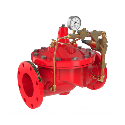
CLA-VAL 50B-4KG1 Installation, operation and maintanance manual

KEUCO
KEUCO 59948 000070 Installation and operating instructions
Vision
Vision TECHCONNECT CONTROL owner's manual

Price Pfister
Price Pfister 0X8 series installation instructions
