manuals.online logo
Brands
  1. Home
  2. •
  3. Brands
  4. •
  5. System Sensor
  6. •
  7. Control Unit
  8. •
  9. System Sensor M500SAP User manual

System Sensor M500SAP User manual

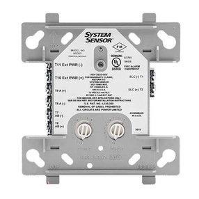
M500SAP Supervised Control Module
INSTALLATION AND MAINTENANCE INSTRUCTIONS
3825 Ohio Avenue, Illinois 60174
1-800-SENSOR2, FAX: 630-377-6495
www.systemsensor.com
BEFORE INSTALLING
This information is included as a quick reference installation guide. Refer to
the control panel installation manual for detailed system information. If the
modules will be installed in an existing operational system, inform the opera-
tor and local authority that the system will be temporarily out of service. Dis-
connect power to the control panel before installing the modules.
NOTICE: This manual should be left with the owner/user of this equipment.
GENERAL DESCRIPTION
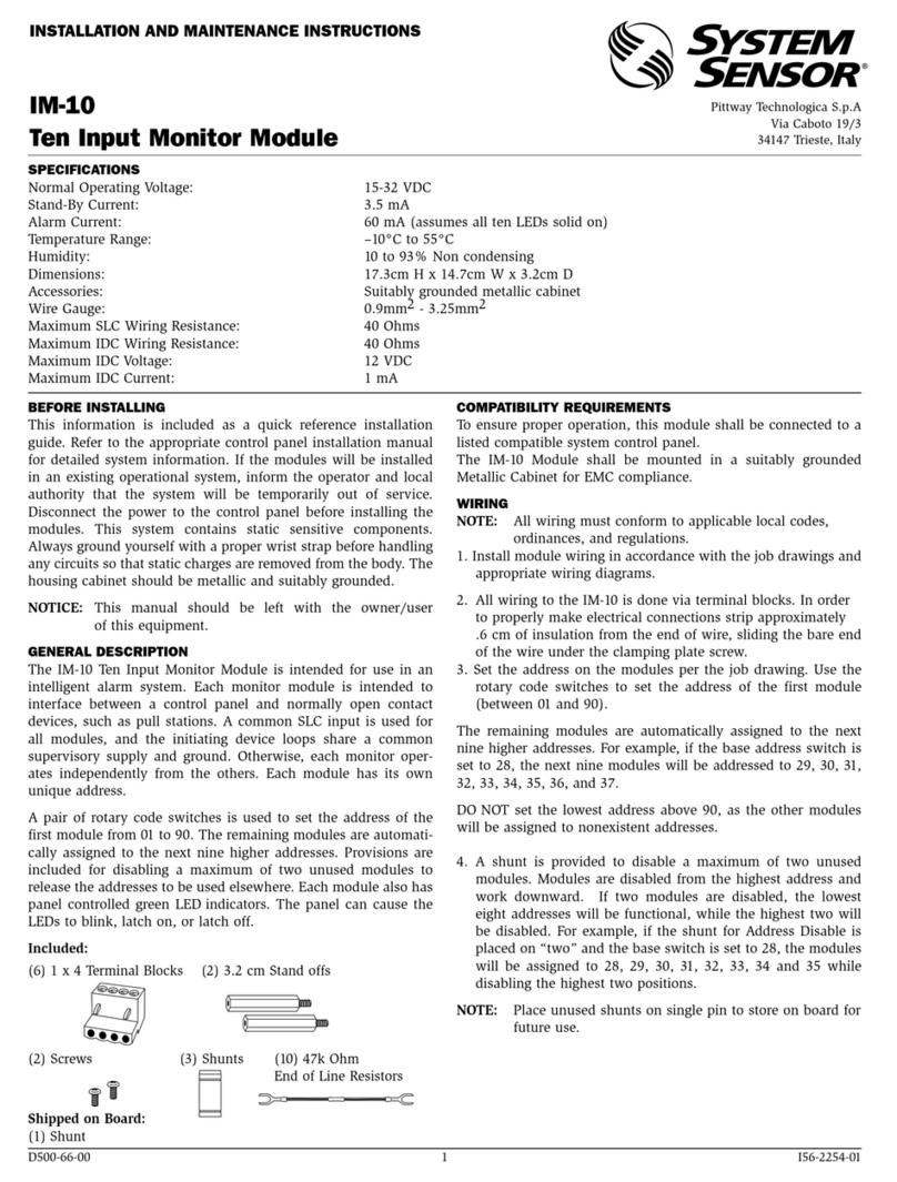
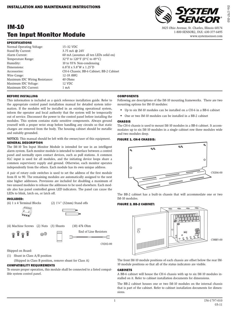
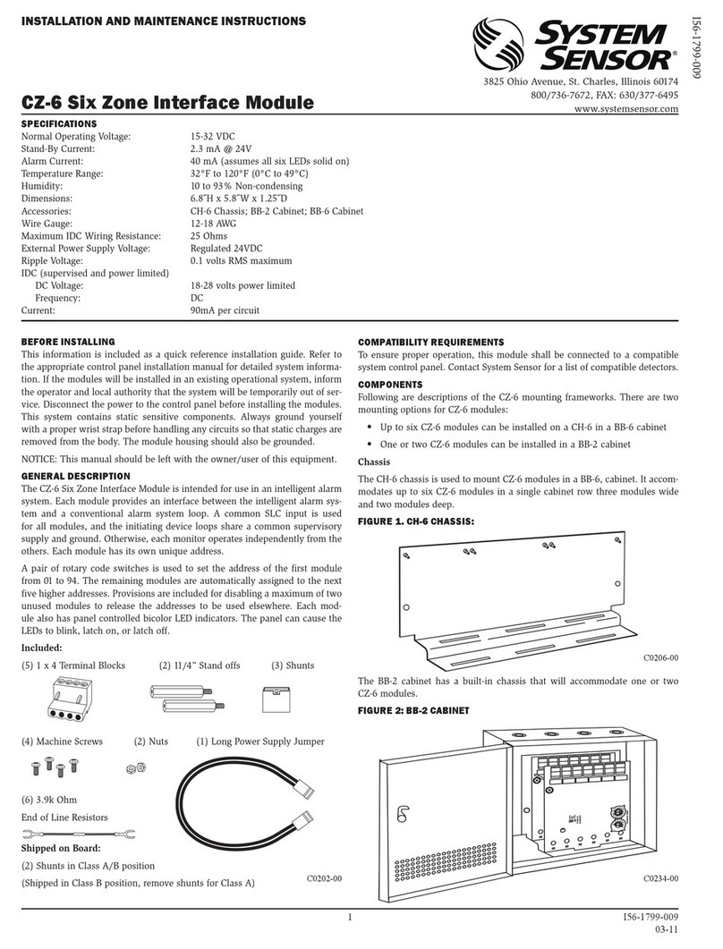
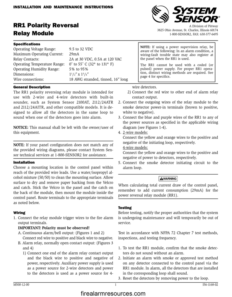
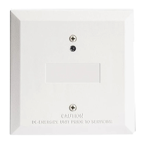
M500SAP Supervised Control Modules are intended for use in intelligent, two-
wire systems, where the individual address of each module is selected using
the built-in rotary decade switches. This module is used to switch an external
power supply, which can be a DC power supply or an audio amplifier (up
to 80 VRMS), to notification appliances. It also supervises the wiring to the
connected loads and reports their status to the panel as NORMAL, OPEN, or
SHORT CIRCUIT. The M500SAP has two pairs of output termination points
available for fault-tolerant wiring and a panel-controlled LED indicator.
COMPATIBILITY REQUIREMENTS
To ensure proper operation, these modules shall be connected to listed com-
patible system control panels only.
MOUNTING
The M500SAP mounts directly to 4-inch square electrical boxes (see Figure 2A).
The box must have a minimum depth of 21/8inches. Surface mounted electri-
cal boxes (SMB500-WH) are available from System Sensor.
SPECIFICATIONS
Normal Operating Voltage: 15 to 32 VDC
Maximum Alarm Current: 6.5mA (LED On)
Average Operating Current: 400 µA max., 1 communication every 5 seconds 47k EOL resistor, 485 uA max.(Communicating, NAC shorted).
Maximum NAC Line Loss: 4 VDC
External Supply Voltage (between Terminals T3 and T4)
Maximum (NAC): Regulated 24VDC
Maximum (Speakers): 70.07 V RMS, 50 W
Max. NAC Current Ratings: For class B wiring system, the current rating is 3A; For class A wiring system, the current rating is 2A
Temperature Range: 32˚F to 120˚F (0˚C to 49˚C)
Humidity: 10% to 93% Non-condensing
Dimensions: 4.67˝ H x 4.26˝ W x 1.40˝ D (118.62 mm H x 108.20 mm W x 35.56 mm D)
Mounts to a 4˝ square (10.16 cm) by 21/8˝(5.4 cm) deep box.
Accessories: SMB500-WH Electrical Box; CB500 Module Barrier
I56-6790-000
FIGURE 1A. CONTROLS AND FIGURE 1B. JUMPER LOCATION
INDICATORS
J1
C1059-00 C0910-00
WIRING
NOTE: All wiring must conform to applicable local codes, ordinances, and reg-
ulations. When using control modules in nonpower limited applications, the
System Sensor CB500 Module Barrier must be used to meet UL requirements
for the separation of power-limited and nonpower-limited terminals and wir-
ing. The barrier must be inserted into a 4˝×4˝×21/8˝ junction box, and the
control module must be placed into the barrier and attached to the junction
box (Figure 2A). The power-limited wiring must be placed into the isolated
quadrant of the module barrier (Figure 2B).
1. Install module wiring in accordance with the job drawings and appropri-
ate wiring diagrams.
UL864 listed
RELAY CONTACT RATINGS
CURRENT RATING MAXIMUM VOLTAGE LOAD DESCRIPTION APPLICATION
2 A 25 VAC PF = 0.35 Non-coded
3 A 30 VDC Resistive Non-coded
2 A 30 VDC Resistive Coded
0.46 A 30 VDC (L/R = 20ms) Non-coded
0.7 A 70.7 VAC PF = 0.35 Non-coded
0.9 A 125 VDC Resistive Non-coded
0.5 A 125 VAC PF = 0.75 Non-coded
0.3 A 125 VAC PF = 0.35 Non-coded
WARNING
All relay switch contacts are shipped in the standby (open) state, but may have transferred to the activated (closed) state during shipping. To ensure that the
switch contacts are in their correct state, modules must be made to communicate with the panel before connecting circuits controlled by the module.
1 I56-6790-000
8/19/2020
2. Set the address on the module per job drawings.
3. Secure module to electrical box (supplied by installer), as shown in
Figure 2A.
IMPORTANT: When using the M500SAP for fire fighter telephone applica-
tions, remove Jumper (J1) and discard. The Jumper is located on the back as
shown in figure 1B. The module does not provide ring back when used as a
fire fighter telephone circuit.
FIGURE 2A. MODULE MOUNTING FIGURE 2B.
WITH BARRIER
ISOLATED
QUADRANT
C1050-00
FIGURE 3. TYPICAL NOTIFICATION APPLIANCE CIRCUIT CONFIGURATION, NFPA CLASS B
(+)
(+)
(+)
(+)
(+)
(+)
47K EOL
RESISTOR
ELR-47K
UL
LISTED EOL RELAY
SHOWN ENERGIZED
24 VDC COIL
EOLR-1
24 VDC CIRCUIT
DO NOT LOOP WIRE ON TERMINALS 10 & 11. BREAK WIRE
RUN TO PROVIDE SUPERVISION OF CONNECTIONS.
TO NEXT CONTROL MODULE OR END-OF-LINE
RELAY. ONE RELAY REQUIRED FOR EACH
CIRCUIT. SOME CONTROL PANELS HAVE RELAY
BUILT IN AND DO NOT REQUIRE EXTERNAL
WIRING. REFER TO PANEL MANUAL.
24 VDC POWER SUPPLY
ISOLATED, REGULATED,
POWER LIMITED PER NFPA 70.
LISTED FOR FIRE PROTECTION
WITH BATTERY BACKUP.
MODULE POLARITIES ARE
SHOWN IN ALARM
CONNECT MODULES TO
LISTED COMPATIBLE
CONTROL PANELS ONLY
SIGNAL LINE CIRCUIT (SLC)
32 VDC MAX.
TWISTED PAIR
IS RECOMMENDED
ALL WIRING SHOWN IS SUPERVISED
AND POWER LIMITED
CONTROL
MODULE
FROM
PANEL OR
PREVIOUS
DEVICE
TO NEXT
DEVICE
*NOTE: ANY FAULT IN THE POWER SUPPLY IS
LIMITED TO THAT ZONE AND DOES NOT
RESULT IN A FAULT IN A SEPARATE ZONE.
(−)
(−)
(−)
(−)(−)
(−)
C0913-07
2 I56-6790-000
8/19/2020
FIGURE 4. TYPICAL FAULT TOLERANT NOTIFICATION APPLIANCE CIRCUIT CONFIGURATION, NFPA CLASS A
(+)
(–)
(+)
(–)
(+)
(–)
(–)
(+)
(–)
(+)
(+)
(–)
ALL WIRING SHOWN IS SUPERVISED
AND POWER LIMITED
MODULE POLARITIES ARE
SHOWN IN ALARM
EOL RESISTOR
IS INTERNAL AT
TERMINALS
8 & 9
UL LISTED EOL
RELAY SHOWN
ENERGIZED
24 VDC COIL
EOLR-1
TO NEXT CONTROL MODULE OR
END-OF-LINE RELAY. ONE RELAY
REQUIRED FOR EACH CIRCUIT.
SOME CONTROL PANELS HAVE
RELAY BUILT IN AND DO NOT
REQUIRE EXTERNAL WIRING.
REFER TO PANEL MANUAL.
CONTROL
MODULE
TO
NEXT
DEVICE
SIGNAL LINE CIRCUIT (SLC)
32 VDC MAX. TWISTED PAIR
IS RECOMMENDED
CONNECT MODULES TO LISTED
COMPATIBLE CONTROL PANELS ONLY
FROM
PANEL OR
PREVIOUS
DEVICE
24 VDC CIRCUIT
DO NOT LOOP WIRE ON TERMINALS 10 & 11.
BREAK WIRE RUN TO PROVIDE SUPERVISION
OF CONNECTIONS.
24 VDC POWER SUPPLY
ISOLATED, REGULATED, POWER
LIMITED PER NFPA 70. LISTED
FOR FIRE PROTECTION WITH
BATTERY BACKUP.
*NOTE: ANY FAULT IN THE POWER SUPPLY
IS LIMITED TO THAT ZONE AND DOES NOT
RESULT IN A FAULT IN A SEPARATE ZONE.
C0914-07
FIGURE 5. TYPICAL WIRING FOR SPEAKER SUPERVISION AND SWITCHING, NFPA CLASS B:
(+)
(–)
(+)
(–)
(+)
(–)
(–)
(+)
(–)
(+)
(+)
(–)
AUDIO CIRCUIT
DO NOT LOOP WIRE AROUND TERMINALS
10 & 11. BREAK WIRE TO ENSURE
SUPERVISION OF CONNECTIONS.
SIGNAL LINE CIRCUIT (SLC)
32 VDC MAX.
TWISTED PAIR
IS RECOMMENDED
WIRES MUST BE
SUPERVISED PER NFPA
CONNECT MODULES TO LISTED COMPATIBLE
CONTROL PANELS ONLY
FROM PANEL OR
PREVIOUS DEVICE
CONTROL
MODULE
47K EOL
RESISTOR
ELR-47K
SPEAKERS MUST BE LISTED FOR FIRE
PROTECTION. REFER TO THE RELAY CONTACT
RATING TABLE FOR MAXIMUM LOAD.
TO NEXT
DEVICE
MODULE POLARITIES ARE
SHOWN IN ALARM
TO NEXT CONTROL MODULE
LAST MODULE MUST RETURN
WIRES FOR SUPERVISION
SUPERVISION
AUDIO CIRCUIT WIRING MUST BE TWISTED PAIR AS A MINIMUM. SEE PANEL INSTALLATION MANUAL FOR DETAILED INFORMATION.
AUDIO AMPLIFIER, 70.7 Vrms MAX.
AMPLIFIER MUST PROVIDE WIRING
SUPERVISION PER NFPA.
*NOTE: ANY FAULT IN THE POWER SUPPLY IS LIMITED TO THAT ZONE AND DOES NOT RESULT IN A FAULT IN A SEPARATE ZONE.
C0915-04
3 I56-6790-000
8/19/2020
System Sensor®is a registered trademark of Honeywell International, Inc.
System Sensor warrants its enclosed product to be free from defects in materials and
workmanship under normal use and service for a period of three years from date of
manufacture. System Sensor makes no other express warranty for the enclosed product.
No agent, representative, dealer, or employee of the Company has the authority to in-
crease or alter the obligations or limitations of this Warranty. The Company’s obligation
of this Warranty shall be limited to the replacement of any part of the product which is
found to be defective in materials or workmanship under normal use and service during
the three year period commencing with the date of manufacture. After phoning System
Sensor’s toll free number 800-SENSOR2 (736-7672) for a Return Authorization number,
send defective units postage prepaid to: Honeywell, 12220 Rojas Drive, Suite 700, El Paso
THREE-YEAR LIMITED WARRANTY
TX 79936 USA. Please include a note describing the malfunction and suspected cause of
failure. The Company shall not be obligated to replace units which are found to be defec-
tive because of damage, unreasonable use, modifications, or alterations occurring after
the date of manufacture. In no case shall the Company be liable for any consequential
or incidental damages for breach of this or any other Warranty, expressed or implied
whatsoever, even if the loss or damage is caused by the Company’s negligence or fault.
Some states do not allow the exclusion or limitation of incidental or consequential dam-
ages, so the above limitation or exclusion may not apply to you. This Warranty gives you
specific legal rights, and you may also have other rights which vary from state to state.
FCC STATEMENT
This device complies with part 15 of the FCC Rules. Operation is subject to the following two conditions: (1) This device may not cause harmful interference,
and (2) this device must accept any interference received, including interference that may cause undesired operation.
NOTE: This equipment has been tested and found to comply with the limits for a Class B digital device, pursuant to Part 15 of the FCC Rules. These limits
are designed to provide reasonable protection against harmful interference in a residential installation. This equipment generates, uses and can radiate radio
frequency energy and, if not installed and used in accordance with the instructions, may cause harmful interference to radio communications. However, there
is no guarantee that interference will not occur in a particular installation. If this equipment does cause harmful interference to radio or television reception,
which can be determined by turning the equipment off and on, the user is encouraged to try to correct the interference by one or more of the following
measures:
– Reorient or relocate the receiving antenna.
– Increase the separation between the equipment and receiver.
– Connect the equipment into an outlet on a circuit different from that to which the receiver is connected.
– Consult the dealer or an experienced radio/TV technician for help.
DEVICE AND SYSTEM SECURITY
Before installing this product ensure that the
tamper seal on the packaging is present and
unbroken and the product has not been tampered
with since leaving the factory. Do not install this
product if there are any indications of tampering.
If there are any signs of tampering the product
should be returned to the point of purchase.
It is the responsibility of the system owner to
ensure that all system components, i.e. devices,
panels, wiring etc., are adequately protected to
avoid tampering of the system that could result
in information disclosure, spoofing, and integrity
violation.
FIGURE 6. TYPICAL FAULT TOLERANT WIRING FOR SPEAKER SUPERVISION AND SWITCHING, NFPA CLASS A
(+)
(–)
(+)
(–)
(+)
(–) (+)
(–)
(–)
(+)
(–)
(+)
ALL WIRING SHOWN IS SUPERVISED
AND POWER LIMITED
TO NEXT
DEVICE
SIGNAL LINE CIRCUIT (SLC)
32 VDC MAX.
TWISTED PAIR
IS RECOMMENDED
WIRES MUST BE
SUPERVISED PER NFPA
CONNECT MODULES TO LISTED COMPATIBLE CONTROL PANELS ONLY
FROM
PANEL OR
PREVIOUS
DEVICE
CONTROL
MODULE
SPEAKERS MUST BE LISTED FOR
FIRE PROTECTION. REFER TO THE
RELAY CONTACT RATING TABLE
FOR MAXIMUM LOAD.
47K EOL RESISTOR
IS INTERNAL AT
TERMINALS 8 & 9
MODULE POLARITIES ARE
SHOWN IN ALARM
TO NEXT CONTROL MODULE
LAST MODULE MUST RETURN
WIRES FOR SUPERVISION
SUPERVISION
AUDIO CIRCUIT WIRING MUST BE TWISTED PAIR AS A MINIMUM. SEE PANEL INSTALLATION MANUAL FOR DETAILED INFORMATION.
AUDIO AMPLIFIER, 70.7 Vrms MAX.
AMPLIFIER MUST PROVIDE WIRING
SUPERVISION PER NFPA.
AUDIO CIRCUIT
DO NOT LOOP WIRE AROUND TERMINALS
10 & 11. BREAK WIRE TO ENSURE
SUPERVISION OF CONNECTIONS.
BYPASS CAPACITORS: 100µ
A2143-20 NONPOLARIZED
<10µA LEAKAGE
*NOTE: ANY FAULT IN THE POWER SUPPLY IS LIMITED TO THAT ZONE AND DOES NOT RESULT IN A FAULT IN A SEPARATE ZONE.
C0916-04
4 I56-6790-000
©2020 System Sensor. 8/19/2020
This manual suits for next models

1

Other System Sensor Control Unit manuals

System Sensor SC-6 User manual

System Sensor

System Sensor SC-6 User manual

System Sensor M500M User manual

System Sensor

System Sensor M500M User manual

System Sensor 500 Series User manual

System Sensor

System Sensor 500 Series User manual

System Sensor CR-6 Instruction Manual

System Sensor

System Sensor CR-6 Instruction Manual

System Sensor M902M User manual

System Sensor

System Sensor M902M User manual

System Sensor MOD400R User manual

System Sensor

System Sensor MOD400R User manual

System Sensor M502M User manual

System Sensor

System Sensor M502M User manual

System Sensor MDL3W User manual

System Sensor

System Sensor MDL3W User manual

System Sensor 500 Series User manual

System Sensor

System Sensor 500 Series User manual

System Sensor EM-1SRI User manual

System Sensor

System Sensor EM-1SRI User manual

System Sensor M500M User manual

System Sensor

System Sensor M500M User manual

System Sensor MDL3 Series User manual

System Sensor

System Sensor MDL3 Series User manual

System Sensor RR2 User manual

System Sensor

System Sensor RR2 User manual

System Sensor IM-10 User manual

System Sensor

System Sensor IM-10 User manual

System Sensor CZ-6 User manual

System Sensor

System Sensor CZ-6 User manual

System Sensor i3 Series User manual

System Sensor

System Sensor i3 Series User manual

System Sensor M500DMR User manual

System Sensor

System Sensor M500DMR User manual

System Sensor M502M User manual

System Sensor

System Sensor M502M User manual

System Sensor M502MA User manual

System Sensor

System Sensor M502MA User manual

System Sensor RR1 User manual

System Sensor

System Sensor RR1 User manual

System Sensor M500M User manual

System Sensor

System Sensor M500M User manual

System Sensor M500FP User manual

System Sensor

System Sensor M500FP User manual

System Sensor MDl Series User manual

System Sensor

System Sensor MDl Series User manual

System Sensor M210EA-CZR User manual

System Sensor

System Sensor M210EA-CZR User manual

Popular Control Unit manuals by other brands

NXP Semiconductors TWR-MCF5441X Quick reference guide

NXP Semiconductors

NXP Semiconductors TWR-MCF5441X Quick reference guide

Bodine 1865 Instructions for installation and operation

Bodine

Bodine 1865 Instructions for installation and operation

Pickering PXI 40-510 user manual

Pickering

Pickering PXI 40-510 user manual

EBARA SERVOPRESS LP Original operating instructions

EBARA

EBARA SERVOPRESS LP Original operating instructions

Definox VDCI-MC-FC Maintenance notice

Definox

Definox VDCI-MC-FC Maintenance notice

iRZ 400 Operation manual

iRZ

iRZ 400 Operation manual

ZURN AQUA-GARD ZW1070/15 Installation & maintenance

ZURN

ZURN AQUA-GARD ZW1070/15 Installation & maintenance

Hiltron PCM2 quick start guide

Hiltron

Hiltron PCM2 quick start guide

AWINIC AW21018 manual

AWINIC

AWINIC AW21018 manual

Eaton i-on30R installation instructions

Eaton

Eaton i-on30R installation instructions

Demex Easy GSM Firmware update instructions

Demex

Demex Easy GSM Firmware update instructions

Viessmann 5214 Operating	 instruction

Viessmann

Viessmann 5214 Operating instruction

PEP Modular Computers V1553B user manual

PEP Modular Computers

PEP Modular Computers V1553B user manual

Korg EX-8000 owner's manual

Korg

Korg EX-8000 owner's manual

Margi Presenter-to-Go Springboard user guide

Margi

Margi Presenter-to-Go Springboard user guide

schmersal PSCBR-C-10 Series installation manual

schmersal

schmersal PSCBR-C-10 Series installation manual

Parker Autoclave Engineers 10V Series Operation and maintenance manual

Parker

Parker Autoclave Engineers 10V Series Operation and maintenance manual

SPX APV DELTA M4 operating manual

SPX

SPX APV DELTA M4 operating manual

manuals.online logo
manuals.online logoBrands
  • About & Mission
  • Contact us
  • Privacy Policy
  • Terms and Conditions

Copyright 2025 Manuals.Online. All Rights Reserved.