manuals.online logo
Brands
  1. Home
  2. •
  3. Brands
  4. •
  5. FEAS
  6. •
  7. UPS
  8. •
  9. FEAS SSE30 Series User manual

FEAS SSE30 Series User manual

Betriebsanleitung
Bitte sorgfältig beachten!
Operating
instructions
Please observe carefully!
SSE30
SSE2430 / SSE4830
Für die Modelle:
- konform
Technische Daten Technical Data
Ausgangsgrößen
Regelgrößen
Betriebsdaten
Schutzeinrichtungen
Sicherheitsdaten
Eingangsgrößen
Min. Eingangsspannung siehe Tabelle oben
Max. Eingangsspannung siehe Tabelle oben
Ladestrom siehe Tabelle oben
Ladezeit ca. 400 Sek. (24V) - 240 Sek. (48V)
Ausgangsspannung UNenn
Ausgangsstrom IMax
Strombegrenzung
Restwelligkeit (20MHz)
24 V / 48 V
DC DC
siehe Tabelle oben
2,0 x INENN
< 50 mVSS
Regelabweichung Last
Regelzeit
< 200 mV bei Laständerung 10.....90%
< 10 ms bei Laständerung 10.....90%
Einschaltdauer (ED)
Arbeitstemperatur
Leistungsabweichung bei
Lagertemperaturbereich
100%
-30°C bis +55°C
ab 50°C
-40°C bis +80°C
Kühlung natürliche Konvektion
empfohlener Freiraum je 15 mm
Vorsicherung
Ausgangssicherung
Überlastschutz
MTBF
nicht erforderlich
nicht erforderlich da kurzschlussfest
im Gerät integriert
>380.000 h
Funkentstörgrad
Schutzklasse
gemäß VDE 0871B, EN 55022/B
Schutzklasse II
Schutzkleinspannung
Umgebungsfeuchte
PELV (EN60204), SELV (EN 62368)
95% relative Feuchte im Jahresdurchschnitt
Betauung möglich - tropentauglich
IP 68
IP 20 (BGV A3)
Schutzart Gehäuse
Schutzart Klemmen
Angewandte Bauvorschriften
Mechanik
>30g bei 33Hz in X,Y und Z, gemäß IEC
Rüttelfestigkeit
gemäß VDE
IEC
EN
CSA / UL
Befestigung Hutschienenbefestigung nach DIN46277
oder Wandmontage mit Schrauben
Abmessungen B x H x T 110mm x 132mm x 138mm
Gewicht siehe Tabelle oben
VDE 0100,0110,0113,0551,806 VDE 0100,0110,0113,0551,806
IEC 62368-1,IEC61000-6-1-2-3-4, IEC 62368-1,IEC61000-6-1-2-3-4,
IEC60068-2-11-52,IEC60529 IEC60068-2-11-52,IEC60529
EN62368-1,EN61000-6-1,EN61000-6-2, EN62368-1,EN61000-6-1,EN61000-6-2,
EN61000-6-3,EN61000-6-4,ENV61140 EN61000-6-3,EN61000-6-4,ENV61140
EN61000-4-2,EN60068 EN61000-4-2,EN60068
EN61010-1 EN61010-1
CSA-C 22.2 / UL62368, UL508, UL1950 CSA-C 22.2 / UL62368, UL508, UL1950
Output data
Control data
Operating data
Safety devices
Safety data
Input data
Min. Input voltage see table above
Max. Input voltage see table above
see table above
ca. 400 sec. (24V) - 240 sec. (48V)
Output voltage Unominal
Output current IMax
Current limiting
Residual ripple (20MHz)
24 V / 48 V
DC DC
see table above
2.0 x Inominal
< 50 mVPP
Control deviation load
Control time
< 200 mV with load variation 10.....90%
< 10 ms with load variation 10.....90%
Duty circle
Operating temperature range
Derating
Storage temperature range
100%
-30°C to +55°C
from 50°C
-40°C to +80°C
Cooling selfcooling
recommended respective distance 15 mm
Input fuse
Output fuse
Overload protection
MTBF
not necessary
not necessary, short circuit proof
integrated into device
>380.000 h
Degree of EMI suppression
Protection class
according to VDE 0871B, EN 55022/B
Class II
Extra low safety potential
Ambient humidity
PELV (EN60204), SELV (EN 62368)
95% relative humidity, yearly average dewing
allowed for use in tropical atmosphere
IP 68
IP 20 (BGV A3)
Protection class enclosure
Protection class terminals
Applied design specifications
Mechanical data
>30g at 33Hz in X,Y and Z, acc. to IEC
Vibration proof
according to VDE
IEC
EN
CSA / UL
Mounting On rails according to DIN 46277 or
wallmounting with screws
Dimensions W x H x D 110mm x 132mm x 138mm
Wheigth see table above
Charging current
Charging time
to apply for:
®
- konform GmbH
Postfach 1521
D - 22905 AHRENSBURG
Telefon: 04102 - 42082
Telefax: 04102 - 40930
www.feas.de
©2017
Stand: 06.11.2023
Seite / Page: 1 of 4
Gewicht
weight ca. 3,50kg
Maße
dimensions
BxHxT
WxHxD 110mm x 132mm x 138mm
Wirkungsgrad
Efficiency 97% 98 %
Pufferzeit (U )
NENN
Hold-up-time (U )
NOMINAL
typ. 10,0A - 200 Sek. typ. 5,0A - 200 sec.
10,0A (Boost max. 15A)
Ausgangsstrom
Output current 5.0A (Boost max. 7.5A)
Einstellbereich der
Pufferzeit (T )
dj.
Range of adjustment
Bufferertime (T )
adj.
5 Sek. ..... max. 5 sec. ..... max.
Ladestrom
Charging current 5,0 Amp. 5,0 Amp.
Eingangsspannung
Input voltage
23,5V ....31,0V
DC DC
(U =2,0V+U )
IN MIN buffer
47,0V ....62,0V
DC DC
(U =2,0V+U )
IN MIN buffer
Typ SSE2430 SSE4830
132
110
138
Pufferspannung UPUFF 22,5 V / 46,5 V
DC DC Buffered voltage Ubuffer 22.5 V / 46.5 V
DC DC
gespeicherte Energie siehe Tabelle oben Stored energy see table above
Gepeicherte Energie
stored energy 10,65 Wh / 38,31 kJ
Pufferzeit siehe Tabelle oben Buffer time see table above
Funktionsweise
Das SSE30 ist ein Puffermodul zur Überbrückung von
Netzausfällen im DC-Versorgungsnetz. Die Kühlung erfolgt
über Luftkonvektion am Gehäuse-Kühlprofil. Bitte die “Derating-
Kurve” beachten.
Mode of operation
The SSE30 is a buffer modul to buffer the DC-circuit in case of
power blackouts. The cooling of the device takes place via air
convection at the case heatsink. Please observe the derating
diagram.
Montage
Das SSE kann direkt an DIN-Hutschiene montiert werden, oder
an die Wand geschraubt werden. Beachten Sie dazu die
Hinweise. ACHTUNG! Zur besseren Wärmeabfuhr sollte das
Gerät einen Freiraum von 15mm haben.
Installation
The SSE can be mounted on rail, or at the wall. Take notice of
the mounting alternatives attached.
CAUTION! For improved heat dissipation, the device
should have a minimum free space of 15 mm.
Elektrischer Anschluss
Das Gerät laut Anschluss-Schema unten anschließen. Hierbei
unbedingt die allgemeinen Sicherheitsvorschriften beachten.
Unsachgemäßer Anschluss kann zu einem Defekt des Gerätes
führen.
Electrical connection
Take care of a correct electrical connection. Take the wiring
diagram at the bottom of this side for help. Inappropriate
connection can cause a defect of the device.
Meldekontakte und Kontaktbelegung
Das Überwachungsmanagement des SSE erlaubt
Einstellmöglichkeiten am Gerät und kann über vier integrierte
Relais-Kontakte fernüberwacht werden.
Signal contacts and pin assignment
The monitoring management of the SSE allows a variety of
settings on the device. It can be remotely monitored via four
built-in relay contacts.
Relaisbelegungen(Öffner):
Die Relais sind im Betriebsmodus (DC-anliegend, Pufferkondensatoren
voll, Ausgang zugeschaltet, Temperatur OK) angezogen (NC).
1-7 : DC-Eingang OK
Bei Anliegen einer Eingangsspannung(U ) die
IN
2,0V oberhalb der eingestellten Pufferspannung liegt,
ist das Relais angezogen (NC).
Bei Abfall der Eingangsspannung unter diesen Wert
(U <U ) fällt das Relais ab, und die Meldung “DC-
IN PUFFER
Eingang fehlt” kann entnommen werden.
7 : Relais-Fußkontakt
4-7 : Abschaltwarnung
Bei einem Ladezustand der Pufferkondensatoren von
>33% und einer Betriebstemperatur von <50°C ist das
Relais angezogen (NC).
Bei unterschreiten des Ladezustandes auf <33% oder
erreichen einer Betriebstemperatur von >50°C fällt das
Relais ab, und die Meldung “Abschaltwarnung” kann
entnommen werden. Beachten Sie, dass sich das Gerät
bei weiterer Belastung abschaltet (Ladezustand=leer,
Temperatur zu hoch).
2-7 : Ladevorgang
Bei einem Laden der Pufferkondensatoren von <95%
ist das Relais angezogen (NC) und die Meldung
Ladevorgang abgeschlossen” kann entnommen
werden. Das SSE ist nun voll Einsatzbereit.
Bei einem Ladezustand von >95% fällt das Relais ab.
5-7 : Überlast / Ausgang an
Das Relais ist angezogen, solange der Ausgang zu-
geschaltet ist.
Bei Überlast/-temperatur oder bei manueller Abschaltung
im Pufferbetrieb fällt das Relais ab und die Meldung “Gerät
abgeschaltet” kann entnommen werden.
3-7 : Pufferung - DC O.K.
Das Relais ist angezogen, wenn die Last im Pufferbetrieb
freigegeben ist.
6-7 : Übertemperatur
Der Kontakt ist bei normalen Betrieb geschlossen und bei
Übertemperatur wird der Kontakt geöffnet.
Signal contacts(Opener):
If the device is ready for use (DC-Input-OK, buffer-capacitors full, output is
enabled, temperature is in specified range) all relays are closed (NC).
1-7 : DC-Input-OK
The relay is closed while U is 2,0V(SSE1210) /
IN
higher than U .
buffer
In the case, that U <U the relay drops out and the
IN buffer
message “DC-Input-failed” occurs.
7 : Common relay contact
4-7 : Cut-of warning
The relay is closed while the charge level of buffer-
capacitors is >33% and the device temperature is <50°C.
If the charge level sinks below 33% or the device
temperature exceeds 50°C the relay drops out and the
message “Cut-of warning” occurs.
Please note that the device will switch off if stressed
furthermore (charge level 0%, temperature >50°C).
2-7 : Charging
The relay is closed while the charge level of buffer-
capacitors is higher 95% and the message “charging
completed” occurs. The SSE is now ready for buffer.
If the charge level sinks below 95% the relay drops out.
5-7 : Overload / Output disabled
The relay is closed while the output is enabled.
In case of overload / over-temperature or manual
deactivation of the output the relay drops out and the
message “Device switched off” occurs.
3-7 : Buffering - DC O.K.
The relaycontact is closed if the load for buffering
operation is released and opened if the load is
disconnected.
6-7 : Overtemperature.
The relaycontact is during normal operation closed and
opened with overtemperature.
Anschlußschema / Wiring diagram
Derating
Umgebungstemperatur / Ambient temperature
020100 30 50 70 90 10040 60 80
1,0
2,0
T / C°
Ausgangsstrom / Output current
Iout
Inenn
Dauerbetrieb
Continunous Mode
Boostbetrieb
Boost Mode
Powerboost
Montage auf Hutschiene / Mounting on rail
LED Anzeigen LED Display
Line OK off
Charging
Buffering O.K.
off
red red
red red
off off
Overload
Abschaltwarnung
Cut of warning
green
green
off
yellow
DC Eingang OK
DC Input OK
Überlast/-temperatur, Ausgang aus
Overload/-temperature, Output off
Überlast/-temperatur, Ausgang aus
Overload/-temperature, Output off
Ladung der Kondensatoren <33%
Charge of capacitors <33% Abschaltwarnung
Ladung der Kondensatoren >33%
Charge of capacitors >33% Cut off warning
Kondensatoren voll geladen
Capacitors full charged
Eingangsspannung ist zu klein.
Input voltage is lower as the buffer voltage
Normalladevorgang
Normal-Charging
Pufferbereit
Ready for Buffering
im Pufferbetrieb
at buffer mode
im Netzbetrieb
at line mode
= LED an / on - wenn Last freigegeben = LED aus / off
+
-
ungepufferter
Verbraucher
unbuffered
load
DC
Anschlußschema mit gepufferten und nicht gepufferten Verbrauchern.
Connections for buffered and unbuffered load.
+
-
Power
Supply
AC
+
-
gepufferter
Verbraucher
buffered
load
!
Beim Einschalten eines
komplett entladenen
Gerätes, kann es zu einer
Stromspitze im Eingang
kommen.
When switching on a completely
discharged device, a current spike
can occur in the input.
Adjustment of
buffer time
(5sec. - max.)
Einstellung der
Pufferzeit
(5Sek. - max.)
Anschlußschema nur mit gepufferten Verbrauchern.
Connections for buffered load only.
DC
+
-
Power
Supply
AC
+
-
gepufferter
Verbraucher
buffered
load
Kontaktbelastung der Relais:
- max. Schaltstrom 500mAmp.
- max. Schaltspannung 30V
Contact-load of the relays:
- max. switched current 500mAmp.
- max. switched voltage 30V
!
1 2 34567
interne Verdrahtung - internal wiring
Line O.K.
Charging
Buffering O.K.
Cut of warning
Overload
Overtemperatur
Common Ground
Seite / Page: 2 of 4
1. Allgemeine Sicherheitsvorschriften
Beim Umgang mit Produkten, die mit elektrischen Spannungen in Berührung
kommen, müssen die gültigen VDE / IEC / EN Vorschriften beachtet werden.
Besonders sei auf folgende Vorschriften hingewiesen: VDE 0100, VDE 0550
/ 0551, VDE 0711, VDE 0860, IEC 664, IEC 742, IEC 570, IEC 65
Bei Nichtbeachtung der Bedienungsanleitung oder der Anschlußvorschrift,
z.B. bei Vertauschen der Anschlußklemmen, kann das Gerät oder die
Anlage beschädigt werden und der Betreiber verliert seinen möglichen
Haftungsanspruch.
Werkzeuge dürfen an Geräten, Bauteilen oder Baugruppen nur benutzt
werden, wenn sichergestellt ist, dass die Geräte von der Versorgungs-
spannung getrennt sind und interne elektrische Bauteile entladen sind.
Vor dem Öffnen des Gerätes den Netzstecker ziehen und sicherstellen, dass
das Gerät spannungslos ist und bleibt. Bauteile, Baugruppen oder Geräte
dürfen nur in Betrieb genommen werden, wenn sie vorher in ein
berührungssicheres Gehäuse eingebaut wurden. Während des Einbaus
müssen sie stromlos sein.
Spannungsführende Kabel oder Leitungen mit denen das Gerät, das Bauteil
oder die Baugruppe verbunden sind müssen stets auf Isolationsfehler oder
Bruchstellen untersucht werden. Bei Feststellen eines Fehlers in der
Zuleitung muß das Gerät unverzüglich aus dem Verkehr genommen werden,
bis die defekte Leitungen ausgewechselt worden sind.
Der Anwender hat dafür Sorge zu tragen, dass die angegebenen
Gerätedaten nicht überschritten werden.
Wenn aus den vorgelegten Beschreibungen für den Anwender oder
Erwerber nicht eindeutig hervorgeht, welche Kennwerte für ein Gerät oder
Bauteil gelten, so muss stets ein Fachmann um Auskunft ersucht werden.
Im übrigen unterliegt die Einhaltung von Bau- und Sicherheitsvorschriften aller
Art ( VDE, TÜV, Berufsgenossenschaften ) dem Anwender / Käufer.
1.General safety rules
When working with products which are in contact to dangerous electrical
voltages, attention must be payed to the relevant valid VDE / IEC / EN
regulations. Especialy with refrence to the following rules:
VDE 0100, VDE 0550 / 0551, VDE 0711, VDE 0860, IEC 664, IEC 742, IEC
570, IEC 65
In case of non-observance of this instructions the unit or other equipment
might be damaged and no warranty or liability could be accepted.
When it is necessary to use tools on the device components parts or
subassemblies make sure that the power is disconnected from the device
and all capacities are discharged.
Before opening the equipment disconnect the power cord and make sure
that the contacts are not energized. It is only allowed to take components
parts, subassemblies or device into operation if they are mounted in an
insulated housing. During the installation all devices have to be
disconnected from power sources.
Power cords and leads which are connected to the device, components or
subassemblies have to be inspected for damaged insulation. If a failure is
detected the device or the subassembly has to be put out of service at
once. It is not allowed to take the device or the subassembly into operation
before replacing the damaged power cord.
It is up to the user’s responsibility that the specification limits of the device
are not exeeded.
If the user is not fully able to relate the technical guidelines, a technical
adviser has to be asked for information.
The observance of construction requirements and safety rules (VDE, IEC,
employers liability insurenance i.e.) is subject to the user/customer.
LDR30MH24
Mini DC-USV für die Hutschiene
RZM122-80M
Redundanzmodul
PSU9024
Netzteil gesiebt/geglättet
Verbraucher (z.B. Schütze, Motoren, Magnetventile,
etc.) die nicht ordnungsgemäß nach den relevanten
Richtlinien entstört sind (z.B. Varistoren, RC-Glieder,
etc), können zur Störung bzw. Zerstörung des
Netzgerätes führen.
Der Einsatz von geeigneten Gleichspannungs-
filtern bietet hier einen wirksamen Schutz.
Consumers (e.g. contactors, motors, solenoid valves
etc.) which have not been correctly interference-
suppressed in accordance to the relevant guidelines
(e.g. varistors, RC elements, etc.) may cause power
supply regulation to malfunction.
The use of suitable DC voltage filtering
offers effective protection here.
DC Filter
SFK12
DC Filter
SFK38
DC Filter
SFK70
Befestigung Alternativen.
Mounting alternatives
1.
2.
3.
Geeignet für M6
Schrauben
Suitable for
M6 screws
6,1 mm
Hutschiene
rail
Mutter M5
Nut M5
Schraube M5
Screw M5
Mutter M5
Nut M5
Schraube M5x10
Screw M5x10
Diese Schaltung ist so nicht zulässig!
This circuit is not permitted in this way!
+
-
Power
Supply DC
AC gepufferter
Verbraucher
buffered
load
DC
+
-
Seite / Page: 3 of 4
®
- konform GmbH
Postfach 1521
D - 22905 AHRENSBURG
Telefon: 04102 - 42082
Telefax: 04102 - 40930
www.feas.de
©2017
Seite / Page: 4 of 4
Pufferstrom (Amp.) - Buffering current (Amp.)
10s 20s 30s 40s
200s 300s 1000s 2000s
1min 3min 15min
500s
5min 30min
0
Pufferzeit (s) / Buffering time (s)
SSE2430
Pufferzeit - Buffering time
10Amp. / 200s
15Amp. / 48s
5Amp. / 17min
1,0
2,0
3,0
4,0
5,0
6,0
7,0
8,0
9,0
10,0
11,0
12,0
13,0
14,0
15,0
16,0

This manual suits for next models

2

Other FEAS UPS manuals

FEAS LDR8024-RS Wiring diagram

FEAS

FEAS LDR8024-RS Wiring diagram

Popular UPS manuals by other brands

Sanyo Denki SANUPS E11A Series User Settings Guide

Sanyo Denki

Sanyo Denki SANUPS E11A Series User Settings Guide

Huawei SUN2000 Series quick guide

Huawei

Huawei SUN2000 Series quick guide

INFOSEC UPS SYSTEM M5T Series user guide

INFOSEC UPS SYSTEM

INFOSEC UPS SYSTEM M5T Series user guide

Paradyne 90 installation instructions

Paradyne

Paradyne 90 installation instructions

Njoy Echo Pro Series user manual

Njoy

Njoy Echo Pro Series user manual

Tripp Lite Internet Office INTERNET750U Specifications

Tripp Lite

Tripp Lite Internet Office INTERNET750U Specifications

Tripp Lite SmartPro UPS System SMART550USB owner's manual

Tripp Lite

Tripp Lite SmartPro UPS System SMART550USB owner's manual

Rocket Fish RF-825VA quick start guide

Rocket Fish

Rocket Fish RF-825VA quick start guide

Tripp Lite AGPS5542 owner's manual

Tripp Lite

Tripp Lite AGPS5542 owner's manual

Delta VX Series Installation & Operation Quick Guide

Delta

Delta VX Series Installation & Operation Quick Guide

Delta 600VA Installation and operation guide

Delta

Delta 600VA Installation and operation guide

Delta Ultron HPH series user manual

Delta

Delta Ultron HPH series user manual

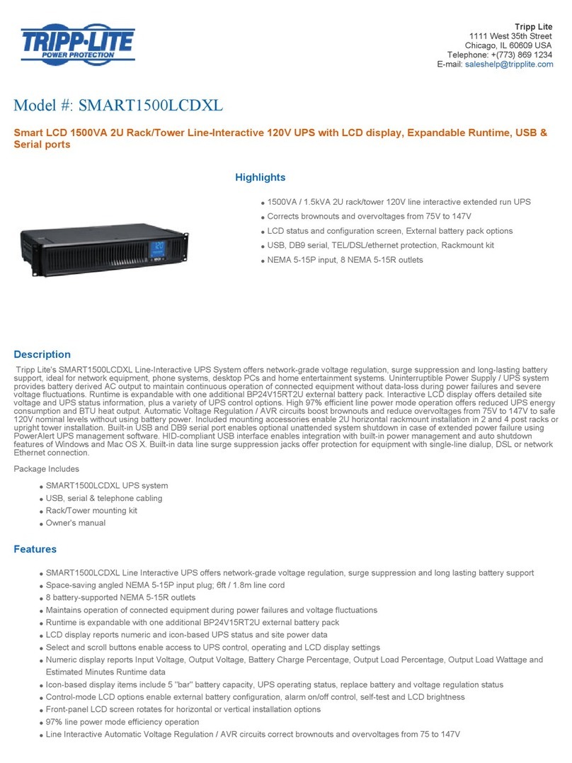
Tripp Lite SMART1500LCDXL specification

Tripp Lite

Tripp Lite SMART1500LCDXL specification

Tripp Lite SmartPro INT 450-1500VA owner's manual

Tripp Lite

Tripp Lite SmartPro INT 450-1500VA owner's manual

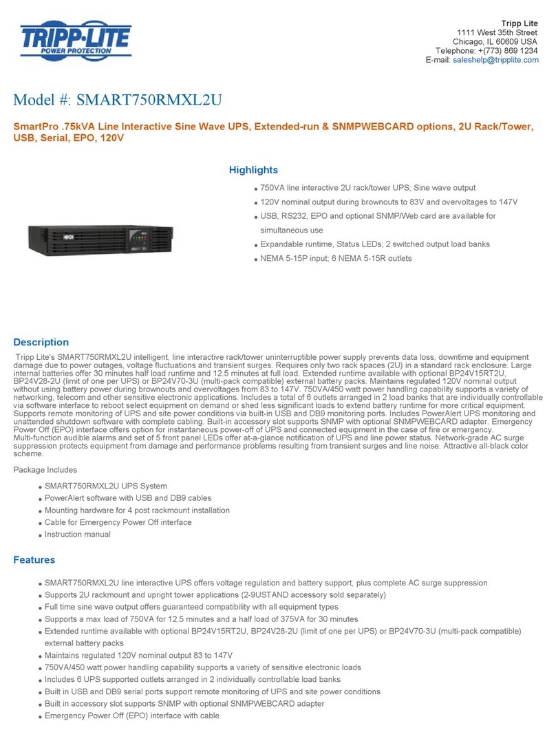
Tripp Lite SmartPro SMART750RMXL2U Specification sheet

Tripp Lite

Tripp Lite SmartPro SMART750RMXL2U Specification sheet

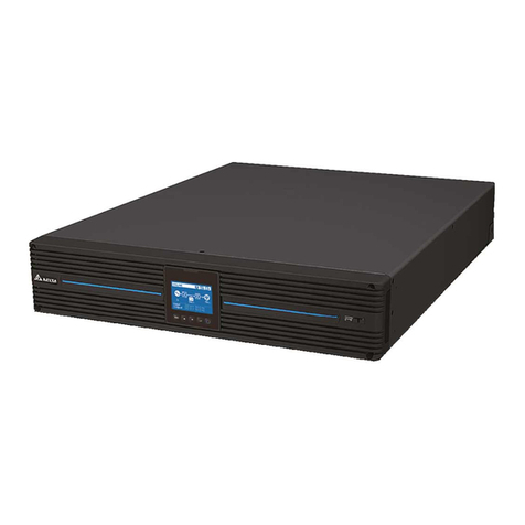
Delta Amplon RT Series user manual

Delta

Delta Amplon RT Series user manual

Tripp Lite BC350 owner's manual

Tripp Lite

Tripp Lite BC350 owner's manual

PowerWalker PowerMust 6054 user manual

PowerWalker

PowerWalker PowerMust 6054 user manual

manuals.online logo
manuals.online logoBrands
  • About & Mission
  • Contact us
  • Privacy Policy
  • Terms and Conditions

Copyright 2025 Manuals.Online. All Rights Reserved.