FEDERAL PACIFIC DST 5-75 Guide

Federal
Pacific
Type
DST
-
5
and
DST
-
15
Magnetic
Air
Circuit
Breakers
r
INSTALLATION
INSTRUCTION
MANUAL
TABLE
OF
CONTENTS
Description
3
Shipment
3
Inspection
upon
Receipt
of
Shipment
3
Storage
before
Installation
4
Basic
Accessories
4
Other
Available
Accessories
4
Present
Ratings
of
DST
Breakers
Uncrating
Setting
Up
the
Main
Circuit
Breaker
Assembly
.
.
.
Checking
for
Proper
Contact
Adjustments
Arc
-
Chute
Installation
Installation
of
Inter
-
Phase
Barriers
Electrical
Operation
Check
Safety
Precautions
Installing
Circuit
Breaker
in
Cell
5
5
5
6
6
7
7
7
8
/
General
Information
5
KV
and
15
KV
Magnetic
Air
Circuit
Breakers
DST
Instructions
and
Adjustments
(
with
sketches
)
8
13
18
Method
of
Operation
and
Schematic
Diagram
18
Sources
of
Control
21
Coil
Data
21
Test
Data
21
DST
Air
Circuit
Breaker
Maintenance
23
Replacement
of
Solenoid
and
Shunt
Trip
Coils
(
with
photo
)
Recommended
List
of
Spare
Parts
24
24
Renewal
Parts
List
5
KV
24
Renewal
Parts
List
ISKV
2
Courtesy of NationalSwitchgear.com
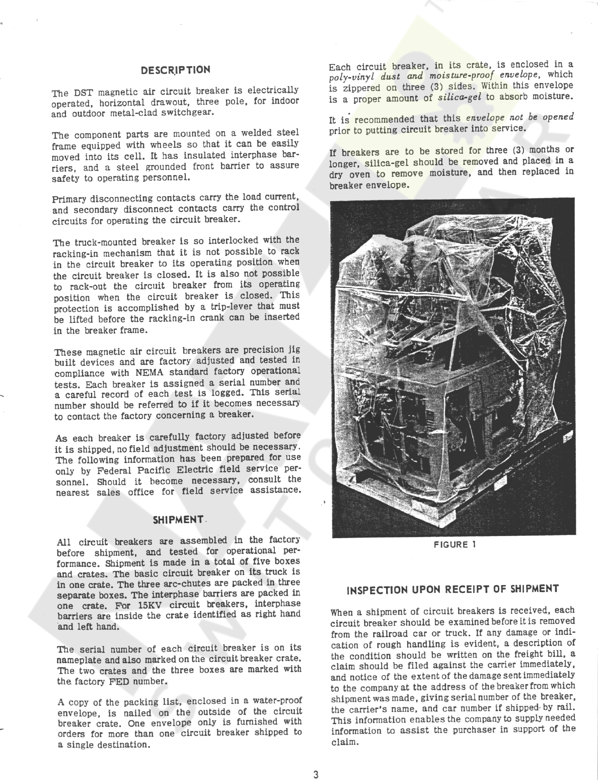
Each
circuit
breaker
,
in
its
crate
,
is
enclosed
in
a
poly
-
vinyl
dust
and
moisture
-
proof
envelope
,
which
is
zippered
on
three
(
3
)
sides
.
Within
this
envelope
is
a
proper
amount
of
silica
-
gel
to
absorb
moisture
.
It
is
recommended
that
this
envelope
not
be
opened
prior
to
putting
circuit
breaker
into
service
.
DESCRIPTION
The
DST
magnetic
air
circuit
breaker
is
electrically
operated
,
horizontal
drawout
,
three
pole
,
for
indoor
and
outdoor
metal
-
clad
switchgear
.
The
component
parts
are
mounted
on
a
welded
steel
frame
equipped
with
wheels
so
that
it
can
be
easily
moved
into
its
cell
.
It
has
insulated
interphase
bar
-
riers
,
and
a
steel
grounded
front
barrier
to
assure
safety
to
operating
personnel
.
If
breakers
are
to
be
stored
for
three
(
3
)
months
or
longer
,
silica
-
gel
should
be
removed
and
placed
in
a
dry
oven
to
remove
moisture
,
and
then
replaced
in
breaker
envelope
.
Primary
disconnecting
contacts
carry
the
load
current
,
and
secondary
disconnect
contacts
carry
the
control
circuits
for
operating
the
circuit
breaker
.
The
truck
-
mounted
breaker
is
so
interlocked
with
the
racking
-
in
mechanism
that
it
is
not
possible
to
rack
in
the
circuit
breaker
to
its
operating
position
when
the
circuit
breaker
is
closed
.
It
is
also
not
possible
to
rack
-
out
the
circuit
breaker
from
its
operating
position
when
the
circuit
breaker
is
closed
.
This
protection
is
accomplished
by
a
trip
-
lever
that
must
be
lifted
before
the
racking
-
in
crank
can
be
inserted
in
the
breaker
frame
.
These
magnetic
air
circuit
breakers
are
precision
jig
built
devices
and
are
factory
adjusted
and
tested
in
compliance
with
NEMA
standard
factory
operational
tests
.
Each
breaker
is
assigned
a
serial
number
and
a
careful
record
of
each
test
is
logged
.
This
serial
number
should
be
referred
to
if
it
becomes
necessary
to
contact
the
factory
concerning
a
breaker
.
As
each
breaker
is
carefully
factory
adjusted
before
it
is
shipped
,
no
field
adjustment
should
be
necessary
.
The
following
information
has
been
prepared
for
use
only
by
Federal
Pacific
Electric
field
service
per
-
sonnel
.
Should
it
become
necessary
,
consult
the
nearest
sales
office
for
field
service
assistance
.
SHIPMENT
All
circuit
breakers
are
assembled
in
the
factory
before
shipment
,
and
tested
for
operational
per
-
formance
.
Shipment
is
made
in
a
total
of
five
boxes
and
crates
.
The
basic
circuit
breaker
on
its
truck
is
in
one
crate
.
The
three
arc
-
chutes
are
packed
in
three
separate
boxes
.
The
interphase
barriers
are
packed
in
one
crate
.
For
15
KV
circuit
breakers
,
interphase
barriers
are
inside
the
crate
identified
as
right
hand
and
left
hand
.
FIGURE
1
INSPECTION
UPON
RECEIPT
OF
SHIPMENT
When
a
shipment
of
circuit
breakers
is
received
,
each
circuit
breaker
should
be
examined
before
it
is
removed
from
the
railroad
car
or
truck
.
If
any
damage
or
indi
-
cation
of
rough
handling
is
evident
,
a
description
of
the
condition
should
be
written
on
the
freight
bill
,
a
claim
should
be
filed
against
the
carrier
immediately
,
and
notice
of
the
extent
of
the
damage
sent
immediately
to
the
company
at
the
address
of
the
breaker
from
which
shipment
was
made
,
giving
serial
number
of
the
breaker
,
the
carrier
'
s
name
,
and
car
number
if
shipped
by
rail
.
This
information
enables
the
company
to
supply
needed
information
to
assist
the
purchaser
in
support
of
the
claim
.
The
serial
number
of
each
circuit
breaker
is
on
its
nameplate
and
also
marked
on
the
circuit
breaker
crate
.
The
two
crates
and
the
three
boxes
are
marked
with
the
factory
FED
number
.
A
copy
of
the
packing
list
,
enclosed
in
a
water
-
proof
envelope
,
is
nailed
on
the
outside
of
the
circuit
breaker
crate
.
One
envelope
only
is
furnished
with
orders
for
more
than
one
circuit
breaker
shipped
to
a
single
destination
.
3
Courtesy of NationalSwitchgear.com
GROUND
AND
TEST
DEVICES
STORAGE
BEFORE
INSTALLATION
r
5
KV
Circuit
breakers
arriving
at
the
job
in
advance
of
installation
should
be
stored
indoors
in
a
dry
place
.
In
cases
where
anytime
is
to
elapse
before
the
circuit
breaker
is
to
be
installed
,
the
insulating
parts
should
be
tested
for
proper
insulation
level
.
If
standard
insulation
level
is
not
found
,
the
insulating
parts
should
be
dried
and
retested
.
If
stored
near
new
con
-
struction
work
,
care
should
be
taken
to
protect
from
dust
or
other
materials
by
covering
with
a
tarpaulin
.
Current
Rating
Symbol
1551
-
0314
1552
-
0314
1200
-
Manual
2000
-
Manual
15
KV
1200
-
Manual
2000
*
Manual
Also
available
electrical
(
solenoid
operated
)
for
Specific
Applications
.
1551
-
0455
1552
-
0455
BASIC
ACCESSORIES
There
is
supplied
with
each
metal
-
clad
installation
one
of
the
following
:
1
.
Racking
-
in
crank
2
.
Manual
or
maintenance
closing
lever
3
.
Arc
-
chute
lifting
yoke
4
.
Test
jumper
(
optional
)
5
.
Breaker
handling
doily
(
not
illustrated
)
6
.
Breaker
transport
truck
(
not
illustrated
)
(
outdoor
installations
only
)
OTHER
AVAILABLE
BREAKER
ACCESSORIES
CLOSING
LOCKOUT
SWITCH
5
KV
toggle
switch
5
KV
momentary
switch
15
KV
toggle
switch
15
KV
momentary
switch
1551
-
0534
1551
-
0533
1551
-
0529
1551
-
0528
FIGURE
2
CINCINNATI
RECORDER
ATTACHMENT
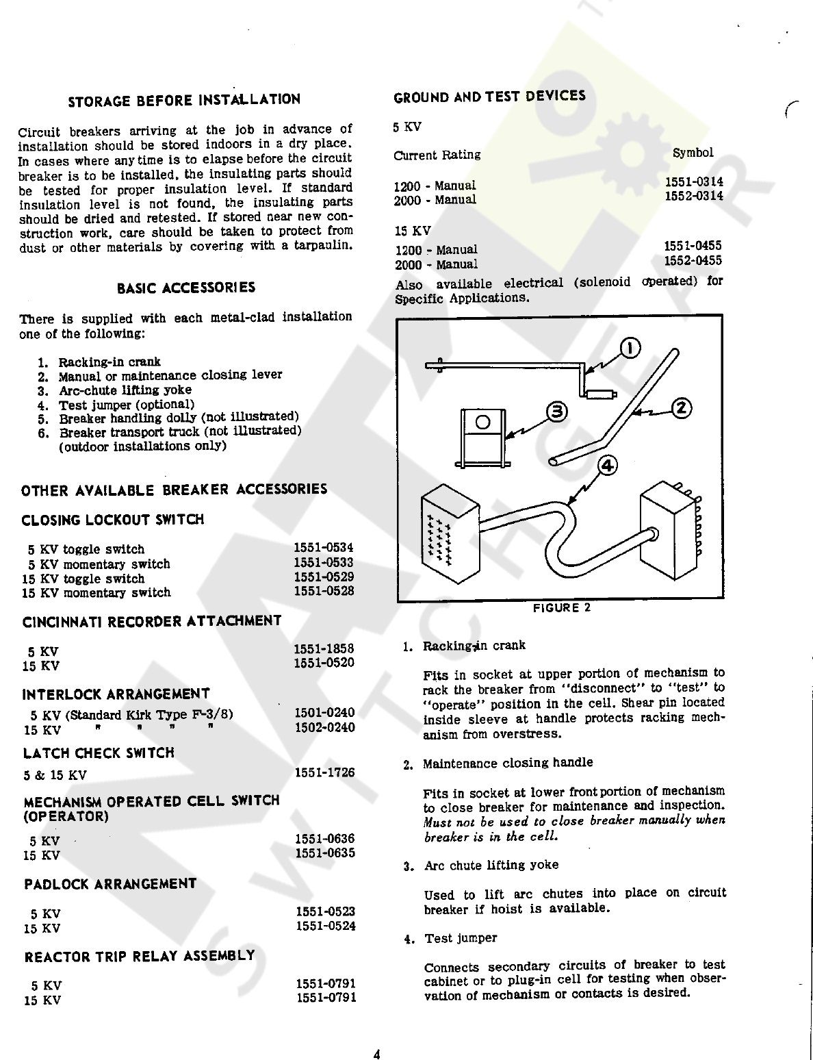
1
.
Racking
*
n
crank
1551
-
1858
1551
-
0520
5
KV
15
KV
Pits
in
socket
at
upper
portion
of
mechanism
to
rack
the
breaker
from
"
disconnect
"
to
"
test
"
to
"
operate
"
position
in
the
cell
.
Shear
pin
located
inside
sleeve
at
handle
protects
racking
mech
-
anism
from
overstress
.
INTERLOCK
ARRANGEMENT
5
KV
(
Standard
Kirk
Type
P
-
3
/
8
)
15
KV
"
LATCH
CHECK
SWITCH
5
&
15
KV
1501
-
0240
1502
-
0240
2
.
Maintenance
closing
handle
1551
-
1726
Fits
in
socket
at
lower
front
portion
of
mechanism
to
close
breaker
for
maintenance
and
inspection
.
Must
not
be
used
to
close
breaker
manually
when
breaker
is
in
the
cell
.
MECHANISM
OPERATED
CELL
SWITCH
(
OPERATOR
)
5
KV
15
KV
1551
-
0636
1551
-
0635
3
.
Arc
chute
lifting
yoke
PADLOCK
ARRANGEMENT
Used
to
lift
arc
chutes
into
place
on
circuit
breaker
if
hoist
is
available
.
5
KV
15
KV
1551
-
0523
1551
-
0524
4
.
Test
jumper
REACTOR
TRIP
RELAY
ASSEMBLY
Connects
secondary
circuits
of
breaker
to
test
cabinet
or
to
plug
-
in
cell
for
testing
when
obser
-
vation
of
mechanism
or
contacts
is
desired
.
5
KV
15
KV
1551
-
0791
1551
-
0791
4
Courtesy of NationalSwitchgear.com

UNCRATING
RATINGS
OF
DST
BREAKERS
If
the
breaker
has
to
be
moved
to
its
proper
location
,
lift
the
breaker
in
its
crate
if
possible
.
If
not
,
then
lift
the
breaker
without
its
arc
-
chutes
and
barrier
.
Always
remove
these
components
before
lifting
a
breaker
.
Fig
.
3
shows
proper
method
of
attaching
lifting
cable
.
Current
Rating
Type
Symbol
DST
5
-
75
DST
5
-
150
DST
5
-
150
DST
5
-
250
DST
5
-
250
1200
1553
-
1653
1555
-
1653
1554
-
1653
1551
-
1653
1552
-
1653
1200
Uncrate
the
breaker
.
Use
nail
-
puller
for
this
purpose
.
Note
that
the
breaker
was
shipped
with
contacts
open
,
and
blocked
open
with
a
shipping
strut
.
2000
1200
2000
SETTING
UP
THE
MAIN
CIRCUIT
BREAKER
ASSEMBLY
1200
Dummy
Dummy
1551
-
0838
1552
-
0838
2000
1
.
After
the
breaker
is
uncrated
,
inspect
for
damage
.
DST
15
-
150
DST
15
-
250
DST
15
-
250
DST
15
-
500
DST
15
-
500
1200
1552
-
1655
1551
-
1655
1551
-
0606
1551
-
1655
1551
-
0606
2
.
Clean
off
any
accumulated
dust
with
a
dry
cloth
.
1200
3
.
The
contacts
were
not
oiled
or
greased
at
the
factory
,
nevertheless
see
that
they
are
free
from
any
oil
or
grease
.
2000
1200
2000
4
.
Check
for
any
obvious
loose
hardware
.
1200
Dummy
Dummy
1551
-
1680
1552
-
1680
5
.
Do
not
install
arc
-
chutes
and
barriers
until
ready
to
push
the
breaker
into
its
cell
.
2000
6
.
First
,
operate
the
breaker
by
means
of
its
maintenance
operating
handle
.
This
is
to
be
inserted
into
its
socket
at
lower
center
of
mechanism
.
See
figure
8
.
Push
the
handle
downward
to
close
the
breaker
until
an
audible
click
is
heard
,
indicating
that
the
breaker
has
latched
into
the
closed
position
.
Check
for
any
binding
or
friction
.
7
.
Remove
the
manual
closing
handle
.
/
8
.
Trip
the
breaker
by
raising
the
lift
-
to
-
trip
lever
.
9
.
Repeat
6
and
8
several
times
to
insure
proper
operation
.
Raise
the
lift
-
to
-
trip
lever
and
insert
the
racking
-
in
handle
in
socket
that
is
uncovered
by
the
pro
-
jection
on
the
trip
bar
.
Note
that
in
order
to
insert
handle
,
the
circuit
breaker
must
be
tripped
open
.
10
.
11
.
Turn
handle
to
rotate
racking
-
in
lever
against
roller
-
lever
against
the
step
in
the
extended
position
(
protruding
outside
the
frame
)
.
12
.
With
handle
still
in
the
socket
,
place
the
manual
closing
lever
in
manual
closing
socket
and
attempt
to
close
the
breaker
.
It
should
trip
-
free
.
Note
how
trip
-
bar
operates
the
cam
to
depress
the
trip
armature
.
13
.
If
circuit
breaker
does
not
operate
properly
,
check
the
contact
adjustments
as
follows
:
FIGURE
3
5
Courtesy of NationalSwitchgear.com
Arcing
Cortact
Position
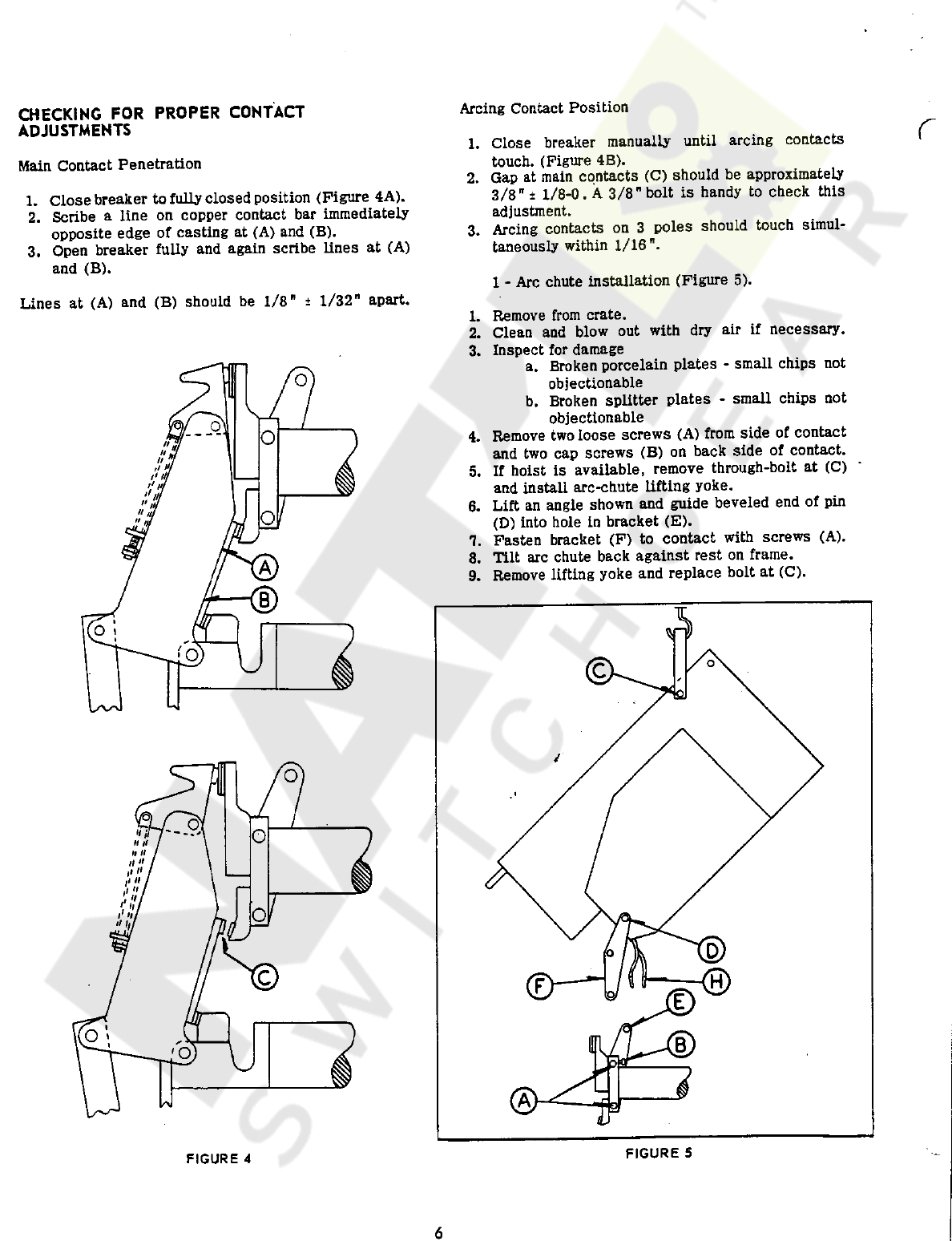
CHECKING
FOR
PROPER
CONTACT
ADJUSTMENTS
r
Close
breaker
manually
until
arcing
contacts
touch
.
(
Figure
4
B
)
.
Gap
at
main
contacts
(
C
)
should
be
approximately
3
/
8
"
±
1
/
8
-
0
.
A
3
/
8
"
bolt
is
handy
to
check
this
adjustment
.
Arcing
contacts
on
3
poles
should
touch
simul
-
taneously
within
1
/
16
1
.
Main
Contact
Penetration
2
.
1
.
Close
breaker
to
fully
closed
position
(
Figure
4
A
)
.
2
.
Scribe
a
line
on
copper
contact
bar
immediately
opposite
edge
of
casting
at
(
A
)
and
(
B
)
.
3
.
Open
breaker
fully
and
again
scribe
lines
at
(
A
)
and
(
B
)
.
3
.
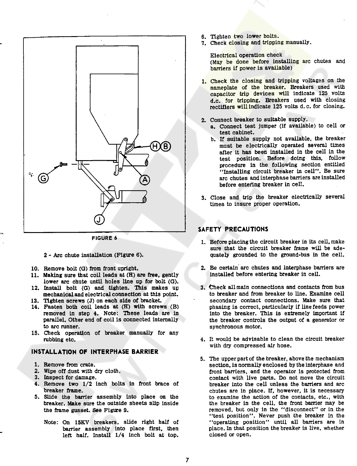
1
-
Arc
chute
installation
(
Figure
5
)
.
Lines
at
(
A
)
and
(
B
)
should
be
1
/
8
"
±
1
/
32
"
apart
.
Remove
from
crate
.
Clean
and
blow
out
with
dry
air
if
necessary
.
Inspect
for
damage
a
.
Broken
porcelain
plates
-
small
chips
not
objectionable
b
.
Broken
splitter
plates
-
small
chips
not
objectionable
Remove
two
loose
screws
(
A
)
from
side
of
contact
and
two
cap
screws
(
B
)
on
back
side
of
contact
.
If
hoist
is
available
,
remove
through
-
bolt
at
(
C
)
and
install
arc
-
chute
lifting
yoke
.
Lift
an
angle
shown
and
guide
beveled
end
of
pin
(
D
)
into
hole
in
bracket
(
E
)
.
Fasten
bracket
(
F
)
to
contact
with
screws
(
A
)
.
Tilt
arc
chute
back
against
rest
on
frame
.
Remove
lifting
yoke
and
replace
bolt
at
(
C
)
.
1
.
2
.
3
.
n
O
o
O
4
.
"
*
/
/
-
7
o
,
/
H
5
.
/
'
/
4
/
'
i f
6
.
"
/
/
>
o
7
.
8
.
A
9
.
B
O
i
;
'
o
o
oi
»
ii
o
;
n
it
a
it
it
"
*
t
'
«
/
a
,
ft
i
r
ii
1
o
o
FIGURE
5
FIGURE
4
6
Courtesy of NationalSwitchgear.com
6
*
Tighten
two
lower
bolts
*
7
.
Check
closing
and
tripping
manually
*
Electrical
operation
check
(
May
be
done
before
installing
arc
chutes
and
barriers
if
power
is
available
)
1
.
Check
the
closing
and
tripping
voltages
on
the
nameplate
of
the
breaker
.
Breakers
used
with
capacitor
trip
devices
will
indicate
125
volts
d
.
c
.
for
tripping
.
Breakers
used
with
closing
rectifiers
will
indicate
125
volts
d
.
c
.
for
closing
.
2
.
Connect
breaker
to
suitable
supply
.
a
.
Connect
test
jumper
(
if
available
)
to
cell
or
test
cabinet
.
b
.
If
suitable
supply
not
available
,
the
breaker
must
be
electrically
operated
several
times
after
it
has
been
installed
in
the
cell
in
the
test
position
.
Before
doing
this
,
follow
procedure
in
the
following
section
entitled
"
Installing
circuit
breaker
in
cell
"
.
Be
sure
arc
chutes
and
interphase
barriers
are
installed
before
entering
breaker
in
cell
.
3
.
Close
and
trip
the
breaker
electrically
several
times
to
insure
proper
operation
.
SAFETY
PRECAUTIONS
FIGURE
6
1
.
Before
placing
the
circuit
breaker
in
its
cell
,
make
sure
that
the
circuit
breaker
frame
will
be
ade
-
quately
grounded
to
the
ground
-
bus
in
the
cell
.
2
-
Arc
chute
installation
(
Figure
6
)
.
2
.
Be
certain
arc
chutes
and
interphase
barriers
are
installed
before
entering
breaker
in
cell
.
10
.
Remove
bolt
(
G
)
from
front
upright
.
11
.
Making
sure
that
coil
leads
at
(
H
)
are
free
,
gently
lower
arc
chute
until
holes
line
up
for
bolt
(
G
)
.
12
.
Install
bolt
(
G
)
and
tighten
.
This
makes
up
mechanical
and
electrical
connection
at
this
point
.
13
.
Tighten
screws
(
J
)
on
each
side
of
bracket
.
14
.
Fasten
both
coil
leads
at
(
H
)
with
screws
(
B
)
removed
in
step
4
.
Note
:
These
leads
are
in
parallel
.
Other
end
of
coil
is
connected
internally
to
arc
runner
.
15
.
Check
operation
of
breaker
manually
for
any
rubbing
etc
.
3
.
Check
all
main
connections
and
contacts
from
bus
to
breaker
and
from
breaker
to
line
.
Examine
cell
secondary
contact
connections
.
Make
sure
that
phasing
is
correct
,
particularly
if
line
feeds
power
into
the
breaker
.
This
is
extremely
important
if
the
breaker
controls
the
output
of
a
generator
or
synchronous
motor
.
4
.
It
would
be
advisable
to
clean
the
circuit
breaker
with
dry
compressed
air
hose
.
INSTALLATION
OF
INTERPHASE
BARRIER
5
.
The
upper
part
of
the
breaker
,
above
the
mechanism
section
,
is
normally
enclosed
by
the
interphase
and
front
barriers
,
and
the
operator
is
protected
from
contact
with
live
parts
.
Do
not
move
the
circuit
breaker
into
the
cell
unless
the
barriers
and
arc
chutes
are
in
place
.
If
,
however
,
it
is
necessary
to
examine
the
action
of
the
contacts
,
etc
.
,
with
the
breaker
in
the
cell
,
the
front
barrier
may
be
removed
,
but
only
in
the
"
disconnect
"
or
in
the
"
test
position
"
.
Never
push
the
breaker
in
the
operating
position
"
until
all
barriers
are
in
place
.
In
that
position
the
breaker
is
live
,
whether
closed
or
open
.
1
.
Remove
from
crate
.
2
.
Wipe
off
dust
with
dry
cloth
.
3
.
Inspect
for
damage
.
4
.
Remove
two
1
/
2
inch
bolts
in
front
brace
of
breaker
frame
.
5
.
Slide
the
barrier
assembly
Into
place
on
the
breaker
.
Make
sure
the
outside
sheets
slip
inside
tne
frame
gusset
.
See
Figure
9
.
Note
:
On
15
KV
breakers
,
slide
right
half
of
barrier
assembly
into
place
first
,
then
left
half
.
Install
1
/
4
inch
bolt
at
top
.
i
*
7
Courtesy of NationalSwitchgear.com
matically
pushed
toward
the
operator
and
locked
in
its
operate
position
.
The
breaker
is
now
in
the
operating
position
.
4
.
Remove
the
racking
-
in
handle
.
6
*
Do
not
attempt
to
close
the
circuit
breaker
by
hand
against
an
energized
circuit
.
The
maintenance
operating
handle
should
only
be
used
in
testing
the
mechanical
operation
of
the
circuit
breaker
when
not
in
the
cell
.
r
The
circuit
breaker
is
ready
for
service
,
and
should
be
closed
and
tripped
electrically
several
times
to
assure
that
all
control
circuit
connections
and
contacts
are
satisfactory
.
This
should
be
done
on
a
dead
bus
if
possible
.
If
the
test
must
be
made
on
a
live
bus
,
first
read
carefully
the
preceding
section
entitled
"
Safety
Precautions
"
.
7
.
In
order
that
sufficient
closing
force
and
acceleration
are
attained
,
the
circuit
breakers
should
be
closed
electrically
from
an
adequate
power
source
.
See
NEMA
Standard
SG
-
6
-
213
.
8
.
Remove
the
circuit
breaker
from
the
cell
when
it
is
to
be
examined
for
maintenance
or
repair
.
Close
and
fasten
the
cell
door
if
breaker
is
to
be
tested
on
live
bus
.
9
.
When
testing
the
circuit
breaker
,
make
sure
the
circuit
breaker
control
switch
has
a
"
do
not
operate
"
tag
on
it
.
5
.
When
it
is
desired
to
rack
the
breaker
into
the
Test
position
,
first
trip
the
breaker
electrically
by
operating
control
switch
,
then
insert
racking
-
in
handle
.
INSTALLING
CIRCUIT
BREAKER
IN
CELL
Before
placing
the
circuit
breaker
in
the
ceil
,
proceed
as
follows
:
a
.
Before
shipment
,
the
circuit
breaker
closing
relays
in
the
top
of
the
cells
are
"
blocked
"
.
Remove
these
blocks
,
thus
allowing
the
relays
to
operate
.
Rotate
the
racking
-
in
handle
counter
clock
-
wise
eleven
(
11
)
times
.
Shutter
will
close
,
and
secondary
contacts
will
be
disconnected
.
6
.
Remove
the
racking
-
in
handle
.
b
.
See
that
the
secondary
sliding
panel
,
with
its
.
plug
-
in
block
,
is
held
at
the
front
of
the
mechanism
housing
by
its
lock
-
pin
.
To
operate
in
Test
position
,
release
secondary
contact
lock
-
in
pin
and
push
sliding
panel
forward
until
its
contacts
engage
contacts
in
the
cell
.
The
breaker
can
now
be
operated
electrically
in
the
Test
position
.
c
.
Insert
racking
-
in
handle
.
Rotate
handle
counter
-
clockwise
until
lever
-
and
-
roller
assembly
is
against
its
stop
.
This
assembly
is
in
the
rear
of
the
breaker
on
top
of
the
mechanism
housing
.
Racking
-
in
lever
should
protrude
outside
the
frame
before
placing
breaker
in
frame
.
7
.
Insert
the
racking
-
in
handle
.
The
circuit
breaker
can
be
racked
to
the
disconnect
position
by
rotating
the
racking
-
in
handle
counter
clock
-
wi
^
e
six
(
6
)
times
.
The
secondary
contact
sliding
panel
should
be
pulled
forward
to
its
operating
position
and
locked
there
by
its
lockpin
,
otherwise
there
will
be
voltage
on
the
control
wiring
of
the
circuit
breaker
.
Place
breaker
in
its
cell
,
and
push
until
lever
-
and
-
roller
assembly
hits
against
horizontal
racking
-
in
hook
which
is
mounting
on
rear
of
cell
.
1
.
Rotate
racking
-
in
handle
clockwise
six
(
6
)
turns
.
Circuit
breaker
will
at
first
back
out
a
little
and
then
go
forward
to
Test
position
as
shown
by
the
indicators
on
the
right
-
hand
side
-
sheet
.
Note
:
As
stated
previously
,
under
"
Description
"
,
the
circuit
breaker
has
to
be
open
before
the
operator
can
insert
the
racking
-
in
handle
into
its
socket
.
Therefore
,
it
is
impossible
to
rack
a
closed
circuit
breaker
from
Test
to
operating
position
,
or
from
operating
to
test
position
.
2
.
Remove
racking
-
in
handle
.
To
operate
breaker
in
Test
position
,
release
secondary
contact
lock
-
pin
and
push
sliding
panel
forward
until
its
contacts
engage
similar
contacts
in
the
cell
plug
in
block
.
The
breaker
can
now
be
closed
and
tripped
electrically
several
times
to
test
the
control
circuits
.
GENERAL
INFORMATION
5
KY
AND
15
KV
MAGNETIC
AIR
CIRCUIT
BREAKERS
3
.
Insert
the
racking
-
in
handle
.
BREAKER
-
Deod
Front
-
Figure
7
The
breaker
is
now
open
.
Rotate
racking
-
in
handle
eleven
(
11
)
more
times
clockwise
.
The
shutter
will
be
driven
open
as
shown
by
its
indicator
.
The
secondary
contact
sliding
panel
will
be
auto
-
Note
breaker
has
front
steel
plate
that
closes
against
angle
irons
in
switchgear
cell
making
a
completely
"
dead
front
"
arrangement
!
8
Courtesy of NationalSwitchgear.com

FIGURE
7
BREAKER
FRAME
-
Figures
8
&
9
Breaker
frame
is
a
welded
fabricated
assembly
of
1
/
8
n
and
1
/
4
”
thick
steel
very
amply
braced
.
Four
inch
diameter
wheels
provide
ease
of
withdrawal
.
Breaker
14
position
-
indicator
'
'
mechanically
locked
with
“
breaker
operating
mechanism
”
provides
positive
visual
indication
of
contact
position
.
Veeder
counter
is
supplied
to
record
number
of
oper
-
ations
.
GROUNDING
-
Figure
10
(
Ml
)
Breaker
frame
substantially
grounded
in
both
“
operating
”
and
“
test
”
positions
.
1
/
4
"
x
2
"
copper
bar
solidly
bolted
to
breaker
frame
provides
wiping
action
against
stationary
coil
-
spring
loaded
contact
located
in
cell
and
formed
of
1
/
8
”
x
2
"
copper
.
FIGURE
9
9
Courtesy of NationalSwitchgear.com
1
'
I
J
mm
FIGURE
12
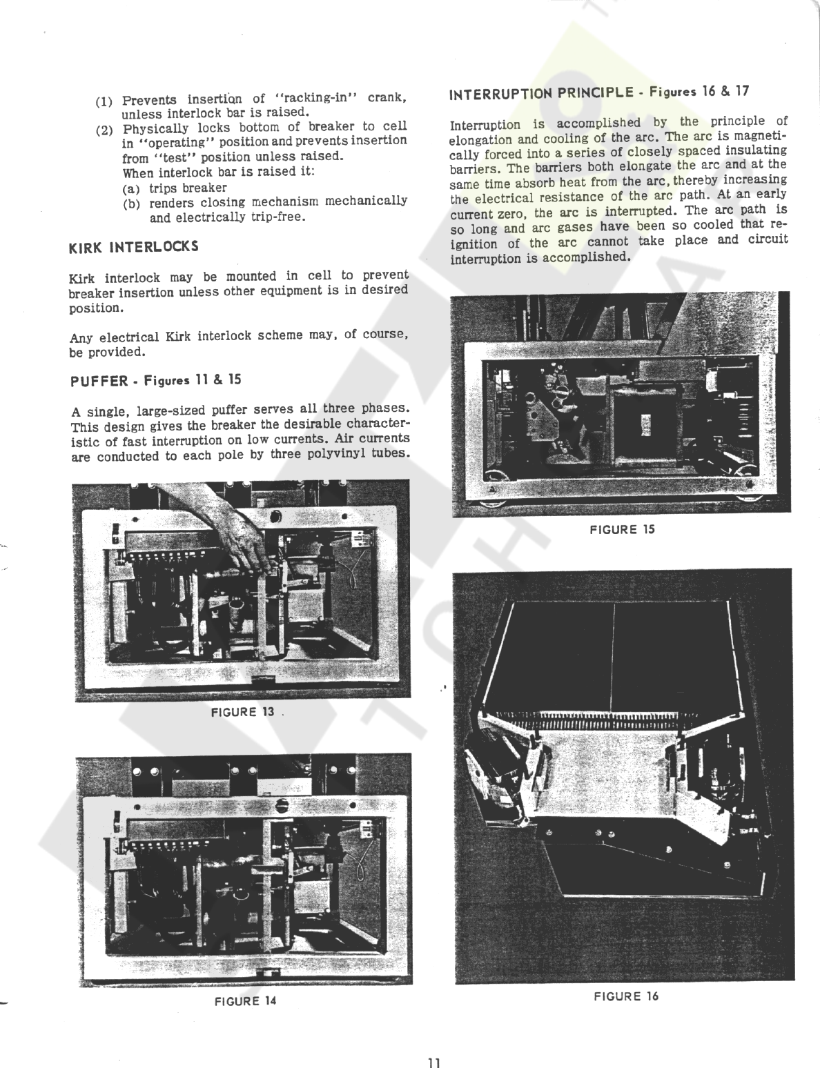
PRIMARY
DISCONNECTS
-
Figure
12
Primary
disconnects
are
self
-
aligning
and
consists
of
high
pressure
finger
segments
of
extruded
copper
,
heavily
silver
plated
.
Pressure
is
exerted
on
each
finger
by
an
individual
leaf
spring
.
A
single
brass
retaining
ring
encircles
the
cluster
of
fingers
.
The
disconnects
are
located
on
the
breaker
(
not
in
the
cell
)
for
convenient
inspection
and
maintenance
when
breaker
is
withdrawn
from
the
housing
.
SECONDARY
DISCONNECTS
-
Figures
11
&
14
Secondary
disconnect
contact
assembly
may
be
(
1
)
locked
in
place
with
pin
to
disconnect
simulta
-
neously
with
main
contacts
or
(
2
)
unlocked
to
remain
connected
with
breaker
in
“
test
"
position
.
FIGURE
10
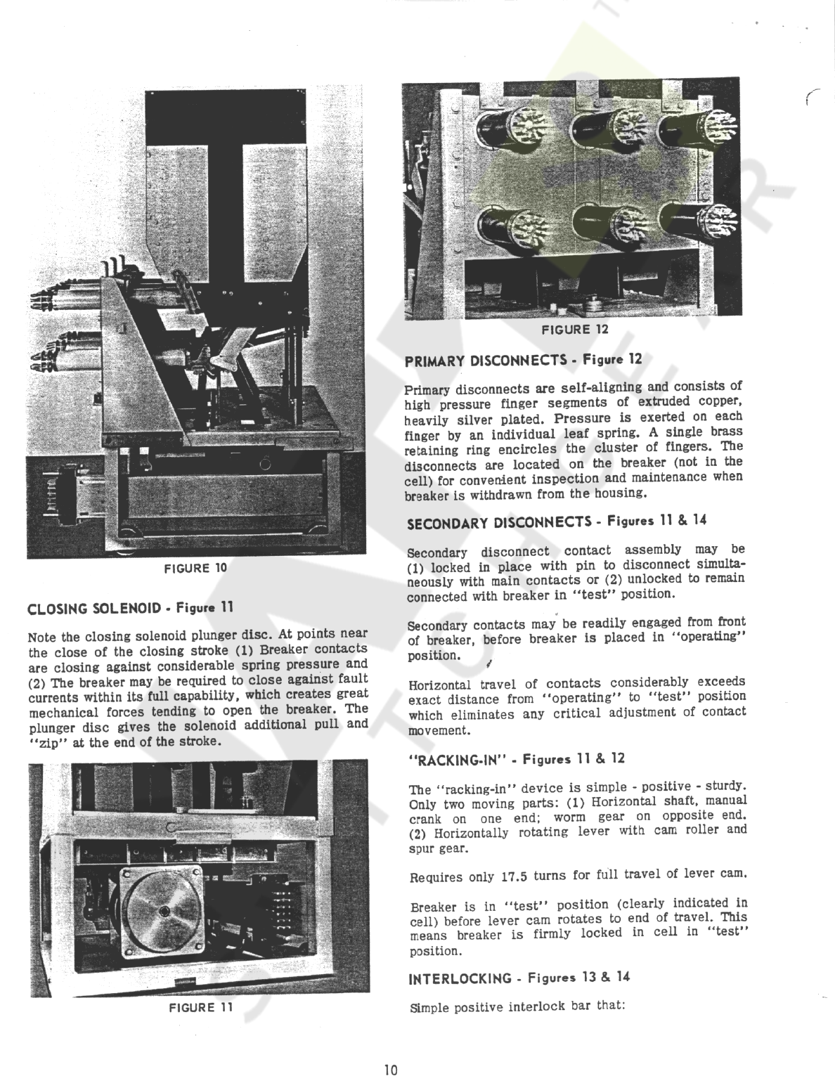
CLOSING
SOLENOID
-
Figure
11
Secondary
contacts
may
be
readily
engaged
from
front
of
breaker
,
before
breaker
is
placed
in
“
operating
"
position
.
Note
the
closing
solenoid
plunger
disc
.
At
points
near
the
close
of
the
closing
stroke
(
1
)
Breaker
contacts
are
closing
against
considerable
spring
pressure
and
(
2
)
The
breaker
may
be
required
to
close
against
fault
currents
within
its
full
capability
,
which
creates
great
mechanical
forces
tending
to
open
the
breaker
.
The
plunger
disc
gives
the
solenoid
additional
pull
and
“
zip
"
at
the
end
of
the
stroke
.
/
Horizontal
travel
of
contacts
considerably
exceeds
exact
distance
from
“
operating
"
to
“
test
"
position
which
eliminates
any
critical
adjustment
of
contact
movement
.
“
RACKING
-
IN
”
-
Figures
11
&
12
The
“
racking
-
in
"
device
is
simple
-
positive
-
sturdy
.
Only
two
moving
parts
:
(
1
)
Horizontal
shaft
,
manual
crank
on
one
end
;
worm
gear
on
opposite
end
.
(
2
)
Horizontally
rotating
lever
with
cam
roller
and
spur
gear
.
Requires
only
17.5
turns
for
full
travel
of
lever
cam
.
Breaker
is
in
“
test
"
position
(
clearly
indicated
in
cell
)
before
lever
cam
rotates
to
end
of
travel
.
This
means
breaker
is
firmly
locked
in
cell
in
“
test
"
position
.
INTERLOCKING
-
Figures
13
&
14
FIGURE
11
Simple
positive
interlock
bar
that
:
10
Courtesy of NationalSwitchgear.com
INTERRUPTION
PRINCIPLE
-
Figures
16
&
17
(
1
)
Prevents
insertion
of
1
‘
racking
-
in
*
*
crank
,
unless
interlock
bar
is
raised
.
(
2
)
Physically
locks
bottom
of
breaker
to
cell
in
“
operating
"
position
and
prevents
insertion
from
“
test
"
position
unless
raised
.
When
interlock
bar
is
raised
it
:
(
a
)
trips
breaker
(
b
)
renders
closing
mechanism
mechanically
and
electrically
trip
-
free
.
Interruption
is
accomplished
by
the
principle
of
elongation
and
cooling
of
the
arc
.
The
arc
is
magneti
-
cally
forced
into
a
series
of
closely
spaced
insulating
barriers
.
The
barriers
both
elongate
the
arc
and
at
the
same
time
absorb
heat
from
the
arc
,
thereby
increasing
the
electrical
resistance
of
the
arc
path
.
At
an
early
current
zero
,
the
arc
is
interrupted
.
The
arc
path
is
so
long
and
arc
gases
have
been
so
cooled
that
re
-
ignition
of
the
arc
cannot
take
place
and
circuit
interruption
is
accomplished
.
KIRK
INTERLOCKS
Kirk
interlock
may
be
mounted
in
cell
to
prevent
breaker
insertion
unless
other
equipment
is
in
desired
position
.
Any
electrical
Kirk
interlock
scheme
may
,
of
course
,
be
provided
.
PUFFER
-
Figures
11
&
15
A
single
,
large
-
sized
puffer
serves
all
three
phases
.
This
design
gives
the
breaker
the
desirable
character
-
istic
of
fast
interruption
on
low
currents
.
Air
currents
are
conducted
to
each
pole
by
three
polyvinyl
tubes
.
FIGURE
15
FIGURE
13
.
if
FIGURE
14
FIGURE
16
1 1
Courtesy of NationalSwitchgear.com

BAFFLE
MATERIAL
OF
15
KV
MAGNETIC
CIRCUIT
BREAKER
-
Figures
16
&
17
ARC
CHUTE
-
Figure
9
By
removing
one
bolt
,
the
arc
chute
may
be
easily
pushed
back
on
a
hinge
,
so
contacts
can
be
inspected
.
This
is
a
very
desirable
maintenance
feature
.
During
fault
interruptions
,
the
arc
which
has
a
temperature
of
several
thousand
degrees
F
comes
into
intimate
contact
with
the
splitter
plates
or
baffles
.
The
material
of
the
baffles
must
be
able
to
withstand
this
drastic
heat
-
shock
without
cracking
or
otherwise
disintegrating
.
CONTACTS
-
Figure
18
Main
contacts
of
heavy
copper
and
inlaid
silver
carry
the
normal
operating
current
when
breaker
is
in
opera
-
tion
.
Arcing
takes
place
between
contacts
of
special
alloys
which
are
extremely
resistant
to
arc
damage
.
The
arc
core
is
surrounded
by
hot
gases
which
need
to
be
cooled
at
a
high
rate
.
Fast
propagation
of
the
arc
helps
to
expose
large
areas
of
the
cool
baffle
plates
to
these
hot
gases
.
Porosity
of
the
baffle
material
is
of
particular
benefit
for
this
action
because
it
multiplies
the
surface
area
in
contact
with
the
gases
.
The
three
principle
attributes
which
we
are
looking
for
are
:
1
.
High
heat
-
shock
properties
.
2
.
Porosity
without
mechanical
weakening
.
3
.
Stability
under
high
humidity
.
These
three
qualities
are
not
independent
of
each
other
and
the
problem
for
the
engineer
consists
in
combining
them
into
the
best
possible
compromise
.
Federal
Pacific
engineers
have
succeeded
in
pro
-
ducing
a
material
which
we
believe
has
the
best
properties
available
today
.
FIGURE
17
Heat
shock
resistance
is
generally
a
property
of
high
zirconium
-
content
materials
and
our
baffle
material
is
a
high
zirconium
-
content
refractory
for
which
we
have
developed
special
treatments
to
assure
the
highest
heat
-
shock
resistant
properties
.
Some
materials
when
subjected
to
high
local
temperatures
^
expand
and
contract
at
different
rates
during
a
heating
and
cooling
cycle
.
This
results
in
permanent
distortion
with
high
"
locked
-
in
”
stresses
.
At
each
short
circuit
the
condition
becomes
worse
and
eventually
leads
to
cracking
of
the
plates
.
Our
material
is
stable
in
that
respect
and
no
internal
stresses
develop
.
Porosity
has
been
increased
progressively
during
the
development
of
the
DST
breaker
and
our
present
material
due
to
its
porosity
has
large
effective
area
.
Moisture
absorption
consists
essentially
of
two
types
:
A
.
Mechanical
absorption
of
moisture
.
B
.
Chemical
binding
of
moisture
.
A
.
Mechanical
absorption
of
moisture
is
determined
by
dipping
the
material
in
water
and
then
measuring
the
amount
of
water
absorbed
.
If
the
absorption
is
of
mechanical
nature
only
,
then
the
water
can
be
driven
out
quickly
by
heating
to
about
220
°
F
.
It
is
most
desirable
to
be
able
to
drive
out
all
of
the
water
in
this
manner
and
not
have
any
chemical
binding
.
Any
porous
material
has
the
ability
to
FIGURE
18
12
Courtesy of NationalSwitchgear.com
Solenoid
cut
-
off
switch
adjustment
absorb
varying
quantities
of
water
by
this
dipping
process
but
so
long
’
as
the
water
can
readily
evaporate
there
is
no
detrimental
side
reaction
to
this
type
of
water
absorption
.
Puffer
Shock
absorber
B
.
When
water
is
chemically
bound
,
it
can
usually
not
be
driven
off
by
a
220
°
F
heating
cycle
but
must
undergo
a
much
longer
heating
at
higher
tempera
-
ture
,
say
400
°
F
.
This
type
of
water
absorption
is
very
undesirable
and
usually
leads
to
excessive
warpage
of
the
plates
while
in
service
.
Auxiliary
switch
contact
Contact
adjustments
1
.
Main
2
.
Arcing
The
Federal
Pacific
baffle
material
has
shown
no
tendency
to
warp
because
it
does
not
chemically
bind
moisture
.
3
,
Cluster
Interlock
and
racking
-
in
mechanism
adjustment
BAFFLE
ASSEMBLY
-
Figure
17
Baffles
on
alternate
sides
of
the
assembly
are
staggered
in
such
a
manner
as
to
elongate
the
arc
more
and
more
as
it
ascends
in
the
arc
chute
.
1
-
Blade
Travel
and
Contact
Engagement
The
total
travel
of
the
breaker
mechanism
from
the
open
to
the
closed
position
is
set
in
the
factory
and
may
not
be
altered
.
Therefore
,
any
adjustment
of
the
contacts
made
in
the
closed
position
will
alter
,
to
a
slight
degree
,
the
position
of
the
blade
when
the
breaker
is
open
.
With
the
breaker
in
the
closed
position
as
shown
in
the
general
assembly
drawings
,
the
deflection
of
the
main
bridging
contacts
should
be
1
/
8
to
1
/
32
,
This
is
usually
measured
by
scribing
a
mark
on
the
copper
bar
when
the
breaker
is
closed
.
Then
scribing
another
mark
when
the
breaker
is
open
.
(
These
marks
coincide
with
the
edge
of
the
blade
castings
on
both
positions
)
.
The
distance
between
the
two
marks
should
measure
1
/
8
to
1
/
32
.
To
alter
this
adjustment
,
it
is
necessary
to
alter
the
effective
length
of
the
operating
rod
by
means
of
its
/
threaded
adjustment
:
1
.
Remove
the
pin
connecting
the
operating
rod
to
the
moving
blade
casting
.
VEEDER
COUNTER
AND
POSITION
INDICATOR
-
Figur
*
14
Breaker
“
position
-
indicator
"
mechanically
locked
with
"
15
KV
operating
mechanism
"
provides
positive
visual
indication
of
contact
position
.
Veeder
counter
is
supplied
to
record
the
number
of
operations
.
INSTRUCTIONS
AND
ADJUSTMENTS
TYPE
DST
-
5
-
250
AND
DST
-
15
-
500
MAGNETIC
AIR
CIRCUIT
BREAKERS
Basic
Adjustments
1
.
Blade
travel
and
contact
engagement
2
.
Arc
-
chute
installation
and
adjustment
Loosen
lock
-
nut
at
opposite
end
of
rod
(
mech
-
anism
cover
may
be
removed
to
do
this
)
.
2
.
3
.
Mechanism
description
4
.
Mechanism
adjustments
(
general
)
Make
one
-
half
turn
adjustment
of
rod
as
nec
-
essary
to
secure
contact
deflection
desired
.
3
.
Mechanism
Adjustments
Note
:
One
-
half
turn
alters
contact
deflection
approximately
1
/
32
"
.
1
.
Adjustment
roller
to
closing
-
lever
2
.
Adjustment
prop
to
roller
4
.
Reassemble
and
tighten
.
3
.
Adjustment
solenoid
travel
2
-
Arc
-
chute
Installation
and
Adjustment
The
arc
-
chute
can
be
installed
relatively
easily
if
the
hinge
pin
and
one
vertical
support
-
plate
are
on
the
arc
-
chute
assembly
before
it
is
lifted
into
position
.
Then
either
manually
or
by
help
of
an
overhead
crane
,
the
arc
-
chute
,
held
in
a
generally
tilted
-
back
position
,
may
be
guided
so
that
the
pin
will
engage
the
hole
in
the
support
plate
that
4
.
Adjustment
overtravei
stop
5
.
Solenoid
back
-
travel
check
Latch
Adjustment
Mechanism
Check
-
points
13
Courtesy of NationalSwitchgear.com
surfaces
involved
;
one
on
the
nose
of
the
closing
lever
-
the
other
on
the
end
of
the
prop
.
is
left
fixed
to
the
upper
bushing
.
With
this
con
-
dition
achieved
,
it
is
relatively
easy
to
engage
the
flathead
screws
to
hold
the
other
upper
plate
to
the
bushing
.
r
The
first
step
in
this
procedure
is
to
adjust
the
position
of
the
roller
with
respect
to
the
closing
lever
.
This
is
done
by
altering
the
position
of
the
main
latch
assembly
by
the
insertion
or
re
-
moval
of
spacing
washers
that
bolt
this
assembly
to
the
mechanism
frame
.
With
the
roller
thus
adjusted
to
the
closing
lever
,
the
breaker
may
be
closed
,
and
the
position
of
the
prop
may
then
be
adjusted
to
the
roller
by
means
of
the
adjusting
castle
-
nut
on
the
prop
return
spring
rod
.
Note
for
5
KV
breaker
:
Cautionl
Install
copper
spacer
when
mounting
arc
-
chute
.
The
arc
-
chute
may
now
be
tilted
forward
and
the
front
support
bolt
or
bolts
tightened
.
It
is
then
possible
to
make
the
terminal
connections
between
the
coil
and
the
upper
bushing
.
If
the
arc
-
chute
is
not
vertical
when
mounted
,
it
is
usually
possible
to
tip
it
the
necessary
amount
after
front
support
bolts
are
loosened
With
this
accomplished
,
the
face
of
the
prop
and
the
face
of
the
closing
lever
will
coincide
when
the
breaker
is
in
the
closed
position
or
when
the
closing
lever
is
brought
up
lightly
against
the
roller
(
by
means
of
the
maintenance
manual
closing
lever
)
.
(
15
KV
only
)
.
3
-
Mechanism
Description
The
closing
mechanism
is
a
solenoid
operated
mechanical
trip
-
free
mechanism
which
closes
and
latches
the
breaker
against
the
operating
forces
exerted
by
the
contacts
,
operating
spring
,
and
electro
-
magnetic
forces
due
to
short
circuits
.
At
any
position
during
the
closing
operation
the
breaker
may
be
tripped
open
,
free
of
the
closing
energy
.
The
solenoid
pushes
on
the
closing
lever
which
is
shaped
somewhat
like
a
crescent
.
This
force
is
then
transmitted
to
the
main
operating
shaft
of
the
breaker
through
a
roller
which
is
held
in
a
fixed
relation
to
these
two
parts
.
If
the
position
of
the
roller
is
altered
,
it
breaks
the
connection
between
these
parts
,
and
the
main
shaft
is
then
free
to
move
to
the
open
position
.
Mechanism
Adjustments
1
.
Adjust
roller
to
closing
-
lever
face
.
(
a
)
Tangent
point
of
roller
1
/
8
"
from
bottom
comer
.
(
b
)
Adjust
by
varying
spacers
in
latch
.
2
.
Adjust
prop
to
roller
.
(
a
)
Tangent
point
1
/
8
"
.
Same
as
closing
-
lever
.
(
b
)
Adjust
by
castle
-
nut
on
prop
spring
guide
.
The
roller
is
held
in
its
fixed
relationship
to
the
moving
parts
by
the
latch
assembly
.
3
.
Adjust
solenoid
travel
.
(
a
)
Close
breaker
manually
.
(
b
)
Push
solenoid
plunger
until
it
hits
lightly
against
closing
lever
and
trip
-
free
roller
.
(
c
)
Gap
between
brass
washers
and
solenoid
back
plate
3
/
32
"
-
1
/
8
"
.
(
over
-
travel
)
(
d
)
Adjust
by
changing
shims
inside
plunger
.
Depressing
the
magnet
armature
releases
the
latch
,
allowing
the
two
internal
toggles
to
collapse
and
thus
release
the
roller
from
its
relatively
fixed
position
.
During
a
normal
closing
operation
this
latch
linkage
remains
firm
,
allowing
the
solenoid
and
closing
lever
to
rotate
the
main
shaft
all
the
way
to
its
closed
position
.
At
this
point
a
prop
snaps
into
place
engaging
the
latch
roller
and
holding
the
main
shaft
in
the
closed
position
.
Simultane
-
ously
,
the
solenoid
cut
-
off
switch
operates
to
de
-
energize
the
solenoid
,
and
,
after
the
necessary
decay
of
current
,
the
solenoid
and
closing
lever
return
to
their
initial
position
leaving
the
operating
shaft
in
the
closed
position
as
held
by
the
roller
and
the
prop
.
4
.
Over
-
travel
stop
adjustment
.
Adjust
so
that
:
(
a
)
Mechanism
cannot
go
over
dead
center
.
(
b
)
Puffer
piston
does
not
hit
rear
spacer
tubes
.
(
c
)
Auxiliary
switch
linkage
does
not
go
over
dead
center
.
(
d
)
Gap
between
stop
and
main
shaft
should
be
at
least
1
/
8
"
minimum
when
breaker
is
closed
.
Caution
!
A
check
should
be
then
made
(
manu
-
ally
)
to
insure
that
this
adjustment
does
not
allow
the
mechanism
to
lock
on
dead
center
.
5
.
Solenoid
back
-
travel
check
.
4
-
Mechanism
Adjustments
(
a
)
Space
between
closing
lever
and
roller
,
when
circuit
breaker
is
open
,
should
be
1
/
16
n
to
1
/
8
n
.
(
b
)
5
KV
only
-
Projection
of
solenoid
plunger
beyond
breaker
frame
1
-
1
/
4
"
maximum
,
The
most
important
adjustment
of
the
mechanism
is
that
of
the
roller
.
The
tangent
point
between
the
roller
and
the
flat
surface
it
rests
against
should
be
approximately
1
/
8
"
from
the
lower
cor
-
ner
of
the
flat
surface
.
There
are
two
such
flat
U
Courtesy of NationalSwitchgear.com
4
.
Piston
should
not
hit
tubular
spaces
in
back
.
Latch
Adjustment
X
\
v
1
.
Latch
armature
engagement
with
segment
,
(
a
)
1
/
16
"
to
5
/
64
"
,
Shock
Absorber
\
L
Should
be
lubricated
inside
with
Lubriplate
or
equivalent
.
\
\
2
.
Gap
between
armature
and
segment
when
latch
is
unloaded
1
/
16
"
to
3
/
32
i
\
2
.
Orifice
size
selected
will
permit
10
%
bounce
or
normal
opening
.
Trip
-
free
opening
will
have
more
bounce
(
approximately
25
%
)
.
t
3
.
Adjust
magnet
frame
to
allow
1
/
32
"
to
1
/
16
"
over
-
travel
of
armature
after
latch
trips
.
(
a
)
Gap
between
armature
rivets
and
magnet
pole
face
approximately
3
/
8
"
when
latch
is
set
.
»
3
.
Piston
-
ring
gaps
should
be
1800
opposite
from
each
other
.
i
4
.
Force
to
trip
breaker
approximately
4
lbs
.
Auxiliary
Switch
5
.
Latch
should
break
freely
when
armature
is
depressed
when
latch
reset
spring
is
overcome
by
hand
.
1
.
Linkage
should
not
go
over
dead
center
on
closing
.
/
2
/
2
.
/
/
3
.
Trip
coil
“
A
”
switch
makes
1
"
or
sooner
before
'
arc
trips
make
.
"
A
”
switches
make
just
before
arc
contacts
touch
.
6
.
Latch
engaging
surfaces
on
armature
and
segment
should
be
free
of
paint
or
foreign
matter
.
7
.
Magnet
pole
face
should
be
lined
up
with
armature
face
.
y
4
.
"
B
"
contacts
make
after
60
%
of
the
breaker
opening
stroke
.
\
Mechanism
Check
Points
1
.
Latch
must
reset
under
all
conditions
(
mechanical
and
electrical
)
.
Contacts
1
.
Main
Contacts
2
.
With
latch
armature
depressed
,
breaker
should
trip
free
before
contacts
have
traveled
half
-
way
closed
.
(
a
)
1
/
8
"
11
/
32
"
deflection
at
top
of
bars
on
all
3
poles
.
(
b
)
Make
certain
the
two
bolts
at
each
end
of
the
insulating
support
are
tight
.
'
X
3
,
Latch
must
have
at
least
1
/
32
"
clearance
.
4
.
At
least
1
/
8
"
clearance
between
closing
lever
and
trip
free
roller
.
Note
:
The
vertical
insulating
piece
that
supports
the
lower
bushing
from
the
breaker
frame
must
be
tight
before
these
adjustments
are
made
.
Any
loosening
of
the
bolts
holding
this
support
will
allow
an
upward
move
-
ment
of
the
lower
bushing
when
the
breaker
is
being
closed
,
thus
reducing
contact
deflection
.
/
5
.
Cut
-
off
switch
operates
simultaneously
when
prop
engages
roller
.
6
.
Over
-
travel
stop
is
not
hit
before
the
closing
armature
has
touched
the
solenoid
backplate
and
will
not
let
breaker
lock
on
dead
center
.
(
c
)
Clean
and
bright
.
(
d
)
50
%
of
line
to
line
when
checked
with
carbon
paper
and
thin
tissue
on
manual
closing
.
Solenoid
Cut
-
Off
Switch
Adjustment
1
.
The
solenoid
cut
-
off
switch
is
adjusted
so
that
it
closes
its
contact
as
prop
snaps
into
position
.
(
e
)
3
/
8
"
gap
±
1
/
16
"
when
arcing
contacts
touch
.
2
.
When
the
mechanism
settles
back
onto
the
prop
,
the
cut
-
off
switch
contacts
must
remain
closed
.
2
.
Adjustment
of
Arcing
Contact
Puffer
(
a
)
To
adjust
arcing
*
contact
,
close
breaker
manually
until
the
main
upper
contacts
are
separated
by
3
/
8
7
.
At
or
near
this
point
,
the
arcing
contacts
just
touch
.
To
adjust
this
,
merely
adjust
the
nut
at
the
end
of
arcing
contact
spring
rod
.
1
.
Should
be
free
of
any
binding
.
2
.
Should
be
air
-
tight
enough
to
restrict
opening
of
breaker
when
nozzles
are
closed
.
(
b
)
With
the
individual
phase
thus
adjusted
,
fine
adjustment
may
then
be
made
to
effect
simui
-
3
.
Should
not
be
lubricated
.
15
Courtesy of NationalSwitchgear.com
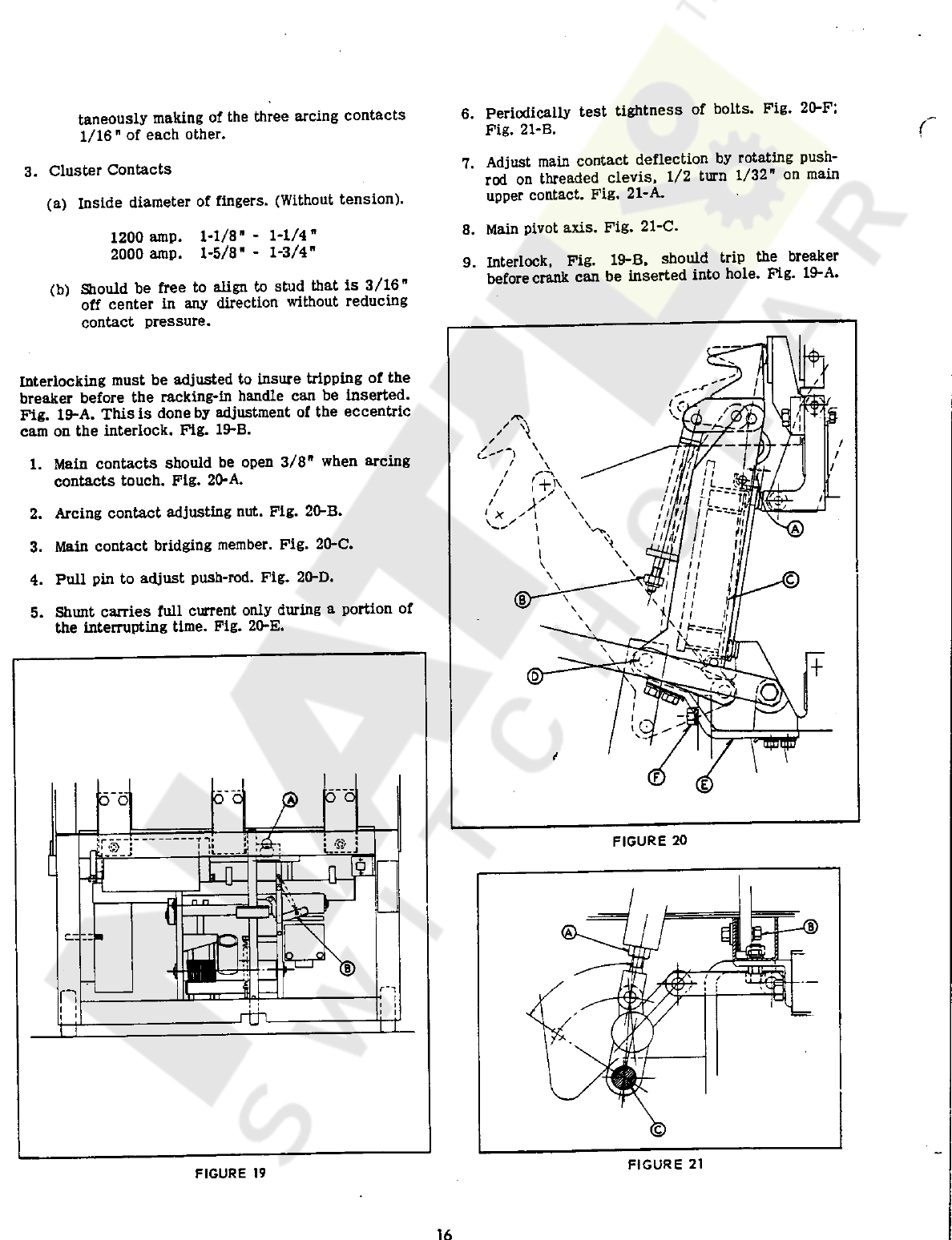
6
.
Periodically
test
tightness
of
bolts
.
Pig
.
20
-
F
;
Fig
.
21
-
B
.
taneously
making
of
the
three
arcing
contacts
1
/
16
"
of
each
other
.
(
7
.
Adjust
main
contact
deflection
by
rotating
push
-
rod
on
threaded
clevis
,
1
/
2
turn
1
/
32
"
on
main
upper
contact
.
Fig
,
21
-
A
.
3
.
Cluster
Contacts
(
a
)
Inside
diameter
of
fingers
.
(
Without
tension
)
.
8
.
Main
pivot
axis
.
Fig
.
21
-
C
.
1
-
1
/
8
"
-
1
-
1
/
4
"
1
-
5
/
8
"
-
1
-
3
/
4
"
1200
amp
.
2000
amp
.
9
.
Interlock
,
Fig
.
19
-
B
,
should
trip
the
breaker
before
crank
can
be
inserted
into
hole
.
Fig
.
19
-
A
.
(
b
)
Should
be
free
to
align
to
stud
that
is
3
/
16
"
off
center
in
any
direction
without
reducing
contact
pressure
.
Interlocking
must
be
adjusted
to
insure
tripping
of
the
breaker
before
the
racking
-
in
handle
can
be
inserted
.
Fig
.
19
-
A
.
This
is
done
by
adjustment
of
the
eccentric
cam
on
the
interlock
.
Fig
.
19
-
B
.
1
.
Main
contacts
should
be
open
3
/
8
"
when
arcing
contacts
touch
.
Fig
.
20
-
A
.
2
.
Arcing
contact
adjusting
nut
.
Fig
.
20
-
B
.
3
.
Main
contact
bridging
member
.
Fig
.
20
-
C
.
4
.
Pull
pin
to
adjust
push
-
rod
.
Fig
.
20
-
D
.
5
.
Shunt
carries
full
current
only
during
a
portion
of
the
interrupting
time
.
Fig
.
20
-
E
.
FIGURE
20
FIGURE
21
FIGURE
19
16
Courtesy of NationalSwitchgear.com


in
and
will
remain
energized
until
contact
cs
/
c
opens
.
Pig
.
22
15
KV
DST
Mechanism
Adjustments
(
1
.
Over
-
travel
stop
,
Pig
.
22
-
A
,
keeps
main
shaft
from
going
dead
center
,
but
should
not
contact
main
shaft
during
electrical
operation
.
The
normally
closed
52
/
y
contact
in
the
control
relay
(
52
/
x
)
circuit
opens
,
thereby
de
-
energizing
52
/
x
which
in
turn
breaks
its
seal
-
in
contact
and
de
-
energizes
the
breaker
closing
coil
.
2
.
Adjustment
,
Pig
.
22
-
B
,
should
be
3
/
32
"
approxi
-
mately
.
This
gives
enough
travel
to
insure
prop
snapping
into
place
.
Should
the
operator
close
the
control
switch
when
the
breaker
is
already
closed
,
the
closing
circuit
will
not
again
be
energized
-
the
52
/
y
coil
will
be
energized
through
the
cs
/
c
and
52
/
aa
contacts
thus
keeping
the
control
relay
(
52
/
x
)
circuit
open
.
3
.
Fig
.
22
-
C
is
de
-
energized
position
of
solenoid
-
plunger
when
breaker
is
in
either
open
or
closed
position
.
4
.
Manual
closing
lever
.
Pig
.
23
-
A
.
Anti
-
pump
Feature
:
If
the
operator
closes
the
control
switch
,
and
holds
the
switch
in
that
position
when
there
is
a
short
circuit
on
the
load
side
of
the
circuit
breaker
,
the
overcurrent
relays
will
function
and
energize
the
shunt
trip
coil
,
which
will
trip
the
breaker
open
.
5
.
Neoprene
pad
to
reduce
shock
.
Pig
.
23
-
B
.
6
.
Exhaust
orifice
of
shock
absorber
.
Fig
.
23
-
C
.
7
.
Pig
.
24
-
A
-
Latch
rotates
and
permits
toggle
to
collapse
when
armature
is
depressed
.
Reclosure
(
pumping
)
of
the
circuit
breaker
is
prevented
because
at
that
instant
the
52
/
y
coil
is
energized
and
its
52
/
y
contact
in
the
circuit
of
the
52
/
x
coil
is
open
.
Therefore
,
the
control
relay
52
/
x
cannot
be
energized
and
thus
attempt
to
close
the
breaker
again
.
8
.
Main
opening
springs
.
Pig
.
23
-
D
,
9
.
Varying
number
of
spacers
will
adjust
position
of
latch
-
roller
to
closing
lever
.
Pig
.
24
-
B
.
10
.
Solenoid
cut
-
off
switch
should
operate
only
after
prop
snaps
into
position
shown
(
breaker
is
closed
)
.
Pig
.
25
-
A
.
11
.
Tangent
point
of
roller
on
surface
to
be
1
/
8
"
approximately
from
lower
comer
of
surface
.
Pig
.
25
-
B
.
12
.
Adjust
roller
to
closing
-
lever
by
moving
latch
-
assembly
.
Pig
.
25
-
C
.
Suppressor
Rectifier
:
This
rectifier
is
shown
across
the
solenoid
closing
coil
52
/
cc
.
Its
function
is
to
limit
the
inductive
kick
when
the
circuit
is
opened
and
thus
reduces
the
arc
across
the
52
/
x
contacts
in
series
with
the
52
/
cc
coil
.
It
is
used
only
when
the
control
circuit
is
direct
current
.
13
.
Nut
to
adjust
prop
to
roller
.
Pig
.
25
-
D
.
Opening
:
,
14
.
3
/
8
"
or
enough
gap
to
insure
tripping
.
Fig
.
24
-
C
.
Assuming
breaker
is
in
the
closed
position
,
energizing
the
trip
coil
from
control
switch
or
relays
opens
the
circuit
breaker
by
mechanical
action
of
its
operating
mechanism
.
METHOD
OF
OPERATION
SEE
SCHEMATIC
DIAGRAM
•
Figure
26
Closing
:
Special
Note
:
Assuming
breaker
is
in
the
open
position
with
voltage
on
the
control
bus
,
close
control
switch
contact
cs
/
c
.
Control
relay
52
/
x
is
energized
through
a
normally
closed
52
/
y
contact
.
Two
(
2
)
circuits
are
made
simul
-
taneously
when
control
relay
52
/
x
contacts
close
.
This
instruction
covers
the
circuit
breaker
as
manufactured
in
standard
form
.
It
is
necessary
to
refer
to
the
actual
diagrams
supplied
with
the
circuit
breaker
,
because
the
diagram
shown
is
typical
,
and
there
are
many
variations
for
meeting
job
requirements
.
a
.
Seal
-
in
circuit
:
Control
relay
52
/
x
is
sealed
in
through
its
own
contact
which
parallels
cs
/
c
contact
.
SOURCES
OF
CONTROL
Federal
Pacific
Type
DST
Air
Circuit
Breakers
are
operated
by
d
-
c
solenoids
and
shunt
trip
coils
.
The
following
methods
of
operating
are
available
.
b
.
Closing
coil
circuit
:
Control
relay
52
/
x
energizes
the
breaker
closing
coil
52
/
cc
which
closes
the
breaker
.
Station
Battery
Closing
and
Tripping
.
The
recommended
method
of
operation
of
the
DST
air
circuit
breaker
is
by
means
of
125
volt
d
-
c
station
battery
-
the
most
reliable
source
of
power
because
it
is
essentially
Cut
-
off
switch
52
/
aa
closes
just
prior
to
the
breaker
main
contacts
,
energizing
the
anti
-
pump
relay
,
52
/
y
,
through
the
52
/
x
seal
-
in
contact
.
52
/
y
seals
itself
18
Courtesy of NationalSwitchgear.com

£
&
yuMPER
»
•
«
r
-
\
1
n
-
»
t
r
(
+
)
T
53
P
.
0
,
FUSE
BLOCK
30
A
.
125
V
.
C
.
L
.
F
.
-
_
LCS
W
-
r
-
X
©
<
^
13
UJ
A
Y
tn
A
13
O
i
y
\
7
<
M
3
U
RECT
.
0
©
bt
UJ
u
<
^
16
it
*
(
ulO
22
CL
o
cn
TC
u
r
_
x
a
Y
L
10
30
A
.
125
V
.
C
.
UF
.
P
.
0
.
FUSE
BLOCK
L
(
-
}
»
t
?
a
Z
'
P
.
0
.
JUMPER
SCHEMATIC
DIAGRAM
LEGEND
cs
-
L
CONTACT
OPEN
WHEN
DEVICE
IS
DE
-
ENERGIZED
.
it
CONTACT
CLOSED
WHEN
DEVICE
^
IS
DE
-
ENERGIZED
.
^
DRAWOUT
DISCONNECT
X
AUXILIARY
RELAY
Y
AUXILIARY
RELAY
CC
CLOSING
COIL
TC
TRIP
COIL
P
.
O
.
PULL
OUT
C
.
L
.
F
.
CURRENT
LIMITING
FUSE
r
CONTROL
SWITCH
CLOSE
C
CONTACT
.
CONTROL
SWITCH
TRIP
T
CONTACT
.
RED
INDICATING
LIGHT
(
CLOSED
)
GREEN
INDICATING
LIGHT
(
OPEN
)
©
o
OPERATING
COIL
OF
DEVICE
RECT
.
SUPPRESSOR
RECTIFIER
FOR
D
.
C
.
CONTROL
ONLY
.
FIGURE
26
independent
of
the
a
-
c
system
conditions
,
and
is
available
at
all
times
.
recommended
that
a
d
-
c
tripping
battery
be
supplied
.
A
constant
,
reliable
source
of
tripping
power
is
essential
for
a
well
-
designed
,
dependable
substation
.
Rectified
AC
Closing
.
This
type
of
operation
finds
its
greatest
application
in
outdoor
installations
or
small
isolated
indoor
installations
where
the
housing
and
maintenance
of
a
125
volt
station
battery
creates
a
major
problem
.
A
single
phase
operating
transformer
is
used
to
supply
240
volt
a
-
c
to
a
rectifier
,
which
furnishes
125
volt
d
-
c
to
operate
the
breaker
.
Capacitor
Trip
.
In
applications
where
it
is
impractical
to
supply
a
source
of
d
-
c
control
,
a
240
volt
a
-
c
capacitor
trip
may
be
used
.
This
requires
that
a
poten
-
tial
transformer
be
connected
to
the
incoming
line
ahead
of
the
circuit
breakers
so
that
the
capacitor
trip
device
is
energized
before
the
breaker
is
closed
.
A
125
volt
d
-
c
shunt
trip
coil
is
used
.
Tripping
Battery
.
If
a
breaker
is
a
-
c
closed
,
it
is
19
Courtesy of NationalSwitchgear.com
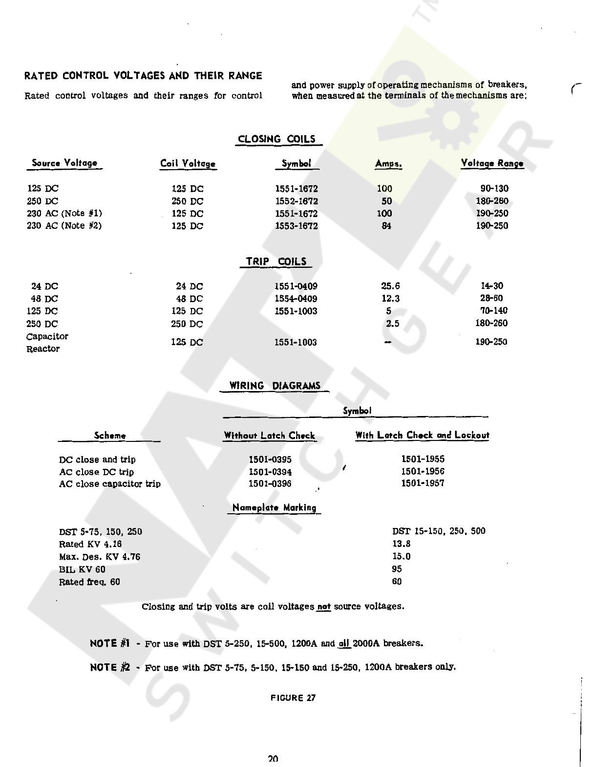
RATED
CONTROL
VOLTAGES
AND
THEIR
RANGE
and
power
supply
of
operating
mechanisms
of
breakers
,
when
measured
at
the
terminals
of
the
mechanisms
are
;
r
Rated
control
voltages
and
their
ranges
for
control
CLOSING
COILS
Source
Voltage
Coil
Voltage
Voltage
Range
Symbol
Amps
*
125
DC
250
DC
230
AC
(
Note
H
)
230
AC
(
Note
#
2
)
125
DC
250
DC
125
DC
125
DC
1551
-
1672
1552
-
1672
1551
-
1672
1553
-
1672
90
-
130
180
-
260
190
-
250
190
-
250
100
50
100
84
TRIP
COILS
24
DC
48
DC
125
DC
250
DC
Capacitor
Reactor
24
DC
48
DC
125
DC
250
DC
25.6
1551
-
0409
1554
-
0409
1551
-
1003
14
-
30
28
-
60
70
-
140
180
-
260
12.3
5
2.5
125
DC
190
-
250
1551
-
1003
WIRING
DIAGRAMS
Symbol
With
Latch
Check
and
Lockout
Scheme
Without
Latch
Check
1501
-
1955
1501
-
1956
1501
-
1957
1501
-
0395
1501
-
0394
1501
-
0396
DC
close
and
trip
AC
close
DC
trip
AC
close
capacitor
trip
/
Nameplate
Marking
DST
5
-
75
,
150
,
250
Rated
KV
4.16
Max
.
Des
.
KV
4.76
BIL
KV
60
Rated
freq
.
60
DST
15
-
150
,
250
,
500
13.8
15.0
95
60
Closing
and
trip
volts
are
coil
voltages
not
source
voltages
.
NOTE
#
1
-
For
use
with
DST
5
-
250
,
15
-
500
,
1200
A
and
all
_
2000
A
breakers
.
NOTE
#
2
-
For
use
with
DST
5
-
75
,
5
-
150
,
15
-
150
and
15
-
250
.
1200
A
breakers
only
.
FIGURE
27
20
Courtesy of NationalSwitchgear.com
This manual suits for next models
5
Table of contents
Other FEDERAL PACIFIC Circuit Breaker manuals

Popular Circuit Breaker manuals by other brands


Siemens-Allis
Siemens-Allis LA-600A instructions

GE
GE Spectra Series AMC3FGB installation instructions

Leviton
Leviton LL630 installation instructions

Doepke
Doepke DFL 8 B SK Series Installation and operating manual

hager
hager WUT10N Safety instructions

ABB
ABB 5HK Series Installation & maintenance instructions