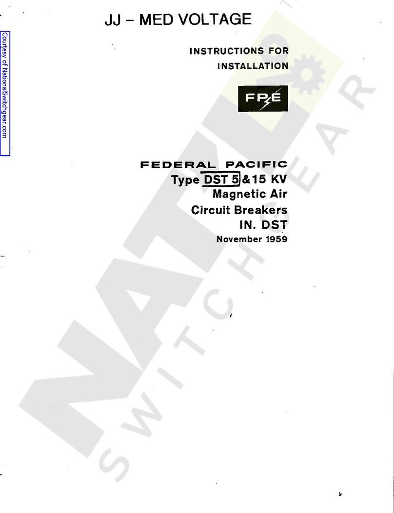
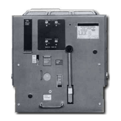
FEDERAL PACIFIC FUSEMATIC FP25-600 User manual

IN-810.9
TYPE FP LOW VOLTAGE
POWER: CIRCUIT BREAKERS
and
FM BREAKERS
JUNE,
1971
CIRCUIT BREAKER FM-25400
PACIFIC ELECTRIC COMPANY
POWER EQUIPMENT SYSTEMS DIVISION
INSTRUCTION
MANUAL
for
(
FUSEMATIC
FP
25
-
600
FP
501600
FM
25
-
600
FM
50
-
1600
N
FP
-
25
-
600
FUSEMATIC
®
EDERAL
1
RH
AV
/
FNI
IF
I
NFWARK
NFW
.
IFRSFY
07101
Courtesy of NationalSwitchgear.com

INSTRUCTION MANUAL
for
TYPE FP LOW VOLTAGE POWER CIRCUIT BREAKERS
and
FM
Manually and Electrically Operated
Part 1
Part 2
3
Part 4
Part 5
Part 6
Part 7
Part
BREAKER FUSEMATIC”
Type FP-25-600 FM-25-600
Type FP-50-1600 FM-50-1600
INDEX
PAGE
General 3
Shipment, Receiving, Handling Storage _______________ 3
Inspection Installation 3
Maintenance 6
Accessories 7
Overcurrent Trip Devices 9
Wiring Diagram
11
Recommended Spare Parts 12
FEDERAL PACIFIC ELECTRIC COMPANY
POWER DIVISION
150AVENUE L, NEWARK, NEWJERSEY 07101
rr
—
FUSEMATIC
®
BREAKERS
*
i
Description
&
&
Part
*
8
EQUIPMENT
SYSTEMS
Courtesy of NationalSwitchgear.com

?
PART 1
GENERAL DESCRIPTION
This Instruction Manual the
and Fusematic breakers only. For
instructions on the FP ‘75 series breakers refer in Instruc-
tion Booklet
The FP line of Low Voltage Power Circuit Breakers and
Fusematic Breakers, which ranges from through
1600A continuous current at 600 Volt ratings, are designed
for simplicity of operation, reliability and easy mainten-
ance. FP Breaker and FM Fusematic are equipped
with a stored energy mechanism mechanically trip free in
any position of the closing cycle, three unit pole assemblies,
fully field adjustable timing devices, multi-range series trip
coils, and telescoping roll-out rails. three position
mechanism is operable with the door closed.
STANDARD ACCESSORIES
Maintenance closing handle 115
Cell racking in handle
PART 2
SHIPMENT, RECEIVING, HANDLING
AND STORAGE
Each FP Breaker and FM Fusematic is thoroughly inspect-
ed and tested before leaving the factory. Breakers are
shipped in individual crates or in the cell compartment.
If breakers are crated, no hooks should be used in handling.
Examine equipment carefully for indication of damage
sustained in transit. If damage in transit is indicated, call
for an immediate inspection by the delivering carrier. Upon
assessment of the damage a claim should he filed with the
carrier or, depending on the nature of the damage, an in-
tent to file for concealed damage should be registered. For
assistance in filing the claim, advise the area sales office of
Federal Pacific Electric Company, giving a full description
of the damage, serial number of the breaker, delivering
carrier’s name, and, if shipped by rail, the car number,
waybill reference, and any other information that might he
of help to the Company in aiding the filing of the
damage claim.
When unpacking, make all items are removed
from the box including
packing
list, instruction book, main-
tenance parts and hardware. Report any shortage immed-
iately. See that identification tags are left on the breaker.
Lifting eyelets are furnished for handling. Do not lift or
handle breaker by the front box or the operating handle.
Clean breaker thoroughly. To remove dust industrial
vacuum cleaner is recommended. If the breaker can be
installed in its permanent location, it is advisable to do so,
even if it is not expected to be for some time.
When breakers must he stored in buildings under
tion, be sure they kept in a space free of dust, moisture,
dirt and in an upright position. It is recommended that
the breaker not be operated prior to final inspection.
PART 3
INSPECTION AND INSTALLATION
SECTION I
Inspection Manually Operated
Breakers
The FP and FM breakers consist of a coordinated set of
assemblies mounted on a steel frame, all carefully adjusted
and locked in place for long and trouble-free operation.
To in properly checking and inspecting breakers
to placing into service, the following steps should be
in the order listed:
1. Remove chutes and interphase
2. Charge stored energy by operating
handle positive stop. Return handle to normal
vertical position by rotation.
NOTE: Charging Operation:
FP Rotate handle counterclock-
wise to engage mechanism and then 1 clockwise to
positive stop. (Figure 1)
FP collapsible handle from
vertical down position to vertical up position. Rotate
clockwise to positive stop. Release handle slowly.
Figure 2
FP
25
-
600
,
FP
50
-
1600
,
covers
FM
25
-
600
FM
50
-
1600
#
IN
810
.
!
0
.
15
A
assist
prior
followed
The
barriers
.
mechanism
rotating
counter
-
clockwise
arc
toa
The
drawout
&
FM
25
-
600
—
90
°
1
-
9252
80
°
1101
-
9251
4
all
Figure
X
&
FM
50
-
1600
—
Unfold
180
°
(
Figure
2
)
.
*
in
sure
that
an
energized
construc
-
are
Courtesy of NationalSwitchgear.com

3. Block the trip device, when supplied, to
prevent tripping.
4. Remove’ right and left hand accelerating springs (Fig.
4).
10.
11
12.
5. Insert closing handle as in
Figure 5 and slowly operate until arcing contacts
touch. All arcing contacts should make simultaneously
with permissible variation of Movable
arcing contact fingers should align with stationary
arcing contacts.
Refer to Part 4 for adjusting instructions if
ment or observed. arcing
contacts designed with side clearances for better
guidance inside the chutes. A side to side move-
ment of is allowable. Close breaker and check
on main contacts:
6. With maintenance closing handle in position and trip
bar in tripped position, proceed to close breaker. Oper-
ating mechanism will now be trip free and contacts
should not make.
7. Remove maintenance handle and breaker
by moving bar.
Replace one pull-off spring right side only.
Inspect each arc chute to be plates are dam-
aged. Replace chutes and interphase barriers on break-
ers. Move contacts in by hand to insure contacts
move in and freely.
To avoid possible injury
NEVER
handle or touch any
of the breaker when the stored energy
mechanism is charged. close button on front
Breaker will close. Depress red trip button
(located in charging handle). Breaker will open.
Recharge stored energy mechanism and close breaker.
Slowly move series trip coil magnet (armature) to
fully closed position. Breaker should trip before arma-
ture touches pole face assembly. Repeat this procedure
on poles.
On draw-out breaker, stored energy mech-
anism, close breaker and move draw-out interlock
plate to the left. Breaker will trip. D/O interlock plate
must be fully to the right before operating
breaker to prevent trip-free operations. (Figure 6).
Figure 6
Charge stored energy mechanism and close breaker.
Pull padlock lever out. Breaker should trip before pad-
lock slot is fully exposed.
14. Check retaining rings and hardware for tightness.
15. Basket and finger should be secured with
Nylok retaining screws. Contact must be free
of dirt and foreign particles. The secondary contacts
should operate freely.
undervoltage
ure
closing
trip
trip
8
9
sure
no
out
moveable
part
Press
cover
.
all
charge
a
i
Figure
4
reset
f
m
Figure
5
4
I
maintenance
#
1151
-
9252
1
/
32
max
.
a
13
.
misalign
-
misadjustments
are
Moveable
assembly
are
Fingers
arc
1
/
8
.
overtravel
l
/
8
"
±
1
/
32
"
.
4
Courtesy of NationalSwitchgear.com

SECTION II
Inspection Electrically Operated
Breakers
The stored mechanism is charged by
fractional AC/DC universal motor. Identifi-
cation, voltage ranges and requirements
below. The stored mechanism charges in
approximately one second.
CHARGING MOTORS FOR FP BREAKERS
STORED ENERGY MECHANISM
Rating
Part Fuse’
D.C.
162.007
15056 20 50
12.0
14976
6.5 25
5.0
14978
6.1 12
3.5
Maximum use control power transformer
forhighervoltage
‘Class 1330
element fuses
From wiring diagram supplied with equipment, or standard
diagram Part 7 of this book, locate motor on
secondary contacts and connect required power source.
Motor will charge when power is applied and shutoff auto-
matically when is
Breaker cannot be closed with the maintenance closing
handle unless stored energy mechanism is charged. 0” all
electrically operated FP breakers the stored energy mech-
anism will recharge immediately following a closing opera-
tion ready for instant if needed.
Follow inspection procedure as outlined
Manually Operated Breakers.”in “Inspection
In addition the following steps are recommended:
16. From wiring diagram locate on secondary
contacts and connect proper control power supply and
controls for shunt close and shunt trip attachments.
Close and open breaker five times electrically and
check for proper operation.
17. Disconnect control power supply. and
breaker manually. Do not leave breaker in the charged
and/or closed position while in storage.
18. Move shunt close solenoid
release closing springs without control power.
SECTION Ill Installation
Before installing breaker in cell, check following points
inside cell:
1. contact support when supplied make
sure all connections are tight and adjusted to proper
dimensions.
2. Ground connections should he tight.
3. Extension rails should be free to in and
check rail stops for tightness.
4. Rail rollers should be free and well lubricated.
5. Main stabs should be tight free of dust
and dirt. Lubricate with contact grease.
6. Check condition of insulating plate in roof of
case. Screws should be tight.
7. Remove control fuses.
8. Place breaker fully extended rails. Make
four rollers inside grooves (Outside
grooves fit into stationary rails inside cell). (Figure 7).
Figure 7
9. Draw-out mechanism on breaker should be in
position.
10. Push breaker inside the cell until racking-i” cranks
engage a positive stop. This is the OUT position.
11. Close and fasten the door. The metal mask provided
on outside of front box freely back it
in contact with the door. The door should
all the way with the breaker in the OUT position.
12. Push interlock to left, insert lever
1101-9251, (Figure 8) into the bottom hole of the
mechanism and, with up-stroke, rack
breaker into the
TEST
position.
Remove lever,
interlock plate should snap into position com-
pletely covering holes.
13. Install control power fuses, energizing the circuit. The
motor will the stored energy mechanism. The
closing and tripping control become energized
in the TEST position.
14. Open and make sure that grounding contact in
cell is in with the breaker. Close door and
check breaker for proper closing and
opening operation.
If breaker operates properly, rack breaker back to OUT
position and leave there until ready to be put into service.
ratchet
-
driven
horsepower
energy
a
are
speci
-
current
energy
fied
FLA
.
LRA
.
Voltage
48
V
A
.
C
.
/
48
V
115
V
A
.
C
.
/
125
V
D
.
C
.
230
V
A
.
C
.
/
250
V
D
.
C
.
240
V
,
Econ
Dual
FPE
#
Motor
162
-
004
162
-
006
terminals
OUT
charging
cycle
completed
.
will
move
as
close
reclosure
comes
drawout
drawout
drawout
an
terminals
drawout
drawout
the
charge
Close
trip
trip
-
circuits
armature
manually
to
door
contact
electrically
Secondary
out
;
move
and
contact
transite
power
moveable
on
sure
all
engage
on
Figure
8
Courtesy of NationalSwitchgear.com

15. To put circuit breaker into service push
interlock to left, insert lever in bottom 3. Make sure all retaining rings are in place.
bole of the mechanism (Figure 8) and
4. Surfaces marked “F” should be lubricated by thin
upward stroke rack breaker into operating position. of “Conducto-Lube before assembly.
Remove
lever. interlock should in
Contacts must be inspected after every known short circuit
and should also he at regular in-
spect& periods. If contacts are found to be worn or
cessively pitted they should be dressed or replaced.
When
reinstalling the arc chutes, adjust the
retaining screws on the arc chute retaining bar so that
the contact insulating block clears the arc chute base when
the breaker is closed.
CONTACT ASSEMBLY
repair or replace arcing contacts,
follows (Figure 11)
1. stored energy
2. Remove arc chutes and barrier.
3. Remove insulating block and fork assembly.
4. Tighten arcing adjusting screw
Figure 9 Figure
PART 4
MAINTENANCE
The breakers with all component have been
tested for performance as per Standards SG
3 and ANSI and proved to be satisfactory
wide margin of safety.
solid and retaining pins.
6. Remove arcing
contact pivot pin and replace
arcing contacts. contacts should be replaced at
one time.
6. Make nylon bushings on arcing pivot pin
are in place and in good condition, when replacing
arcing contact.
A periodic maintenance should be established. An
annual inspection should made for clean,
applications. More frequent inspections should be made
for dirty, corrosive or high-use applications.
Reassemble following the reverse of operations
and adjust per Figs. 10 and 11. In most it is not
to replace contacts, but occasional
and readjustments are
recommended.
The following instructions and should be fol-
lowed carefully:
CONTACT ADJUSTMENT
Figure 10 and 11
MAIN AND ARCING CONTACTS ADJUSTMENT
FOR AND BREAKERS
To replace stationary arcing contacts (Figure remove
unit pole assembly, replace main stud and arcing contact
assembly, part 1151-9939, for 600A breaker and
9937 for breaker.
Adjust as per 10, 11 12.
“A” Main Contact Pressure
Over Travel Mains
Arcing Contact Press
Gap (distance) between
mains when arcing
contacts touch
42-50 lbs., measured at
point of contact
lbs., measured at
of contact
& (Fig. 10)
CHECK POINTS
-Figure 11 and 12
1. Stationary arcing contacts make sure that retaining
screws and contacts are tight.
2. Main contacts should be clean and free
drawout
the
drawout
a
with
drawout
>
drawout
,
i
plate
i
i
position
and
red
IN
appears
.
(
Figure
9
and
9
A
)
.
i
vn
.
n
:
#
240
-
200
”
film
an
(
Fieure
121
.
snap
interruption
inspected
r
ex
-
CAUTION
:
I
ij
If
!
)
proceed
as
moveable
i
mmM
J
&
J
*
mechanism
.
interphase
push
contact
’
s
remove
Charge
i
,
'
tri
4
I
moveable
until
springs
are
5
&
9
A
moveable
i
Both
exten
-
parts
NEMA
sively
contact
sure
with
a
C
37
-
13
a
moveable
schedule
sequence
be
low
-
use
cases
redressing
necessary
adjustments
10
)
,
1151
-
1600
A
&
Figures
contacts
FP
1600
A
FP
600
A
\
600
A
j
—
r
25
-
35
point
1600
A
L
i
±
%
2
“
B
”
-
“
C
”
-
SHOWN
FULLY
CLOSED
'
.
2
-
25
lbs
.
,
measured
at
a
>
oint
Mi
below
tip
of
ontact
6
±
%
2
(
Fig
.
11
)
J
“
D
”
-
B
10
,
\
r
\
r
\
cc
:
:
:
l
:
r
*
-
H
T
’
T
*
Figure
10
Courtesy of NationalSwitchgear.com

PART 5
ACCESSORIES
SHOWN AS ARC
CONTACTS MAKE
11
SHOWN FULLY OPEN
Figure 13
The shunt
trip attachment is mounted directly above the
trip shaft. It is a non-adjustable intended
for intermittent duty only, and its circuit should inter-
rupted only by an auxiliary contact.
SHUNT CLOSE
12
STORED ENERGY MECHANISM
Check latch engagement and adjust if necessary
min. of latch surface contact. Make springs
in place and in good condition. On
breakers, remove motor to make is
free and well lubricated. Reinstall motor. Make that
retaining in place.
Check
mechanism to insure
that all moving parts ate free and well
MECHANISM
Make that all retaining and springs in place
and that the mechanism is free. Replace nylon bumper
rollers if excessive is evident. Make sure that the
operating mechanism when stored energy mech-
anism is slowly and that the trip shaft is free. It
should take no more than 22 inches of torque to
trip the breaker.
GENERAL
Make that current carrying parts secured and The shunt close attachment is mounted on top of the stored
associated hardware is tight. Basket and finger assembly energy mechanism and is used to electrically discharge the
should be secured but free enough to compensate for stored energy mechanism and thus close the breaker. It
alignment in cell. The free up and down movement should is a non-adjustable intermittent duty device and its circuit
be approximately should be interrupted by an auxiliary contact.
J
—
r
c
_
»
•
S
I
:
:
:
:
=
:
v
4
)
SHUNT
TRIP
D
R
Wf
'
=
6
^
4
\
7
v
\
ta
P
IT
Figure
r
i
-
i
s
I
I
J
I
3
-
-
-
a
,
1
-
lr
-
i
L I
m
electro
-
magnet
be
¥
<
c
:
»
T
"
[
:
i
Figure
to
provide
.
062
"
a
sure
electrically
are
operated
sure
roller
sure
all
rings
are
lubricated
.
OPERATING
!
rings
sure
L
wear
resets
charged
ounce
all
sure
%
6
.
Courtesy of NationalSwitchgear.com

UNDERVOLTAGE ATTACHMENT (Figure 15)
SCREW
The attachment is a continuous duty device,
which can be provided with or without a time delay, and
which mechanically trips the breaker if the voltage drops
30% to 60% of normal voltage. It is mechanically
set and has no auxiliary contact in its circuit. The
voltage time delay mechanism is of the pneumatic delay
type. The time is controlled by the adjusting
screw.
To the attachment, hold the move-
able by hand, close breaker and slowly release
the is fully opened, the spring
loaded plunger will be released, strike the lever and
trip the breaker. Check for missing retaining rings and
loose missing and bolts. Check condition of coil.
If attachment is noisy while being energized,
clean faces of and
AUXILIARY SWITCH (Figure 16)
max. 6 stage,
12 contact is available. It
mounted on top of the energy mechanism on the
right hand of the breaker and is by the main
contacts. All contacts are operated by
and factory adjusted provide “a” (normally
open) and
“b" (normally
closed) contacts.
The position and the condition of all contacts can be see”
and inspected through the transparent dust The
contacts may be changed from a b b to by
removing the and inverting the contact bridge.
INTERRUPTING CAPACITY
IN
SINGLE CONTACT
24 20
15
10
7.5
230
250
CONTACT
230
250
BELL
ALARM SWITCH (Figure
Figure 17
A
bell switch attachment is mounted on the
hand side of the breaker and will function only when
breaker is tripped by the trip units. It be
manually and/or electrically reset. Closing of breaker also
resets the switch.
To check the alarm switch attachment, hip breaker with
trip button, the” with shunt trip. In both cases the switch
should not be actuated. Trip breaker by moving the series
trip coil magnet the switch should operate.
is
switch
A
stored
operated
side
phenolic
moveable
cams
are
to
covers
.
to
or
a
cover
TYPE
R
-
4
AUXILIARY
SWITCH
INTERRUPTING
RATING
AMPS
D
.
C
.
•
ir
.
A
.
C
.
D
.
C
.
Inductive
Volts
Non
-
Inductive
Inductive
Non
-
Inductive
48
30
115
50
2.0
125
2.5
15
25
DELAY
.
45
0.5
ADJUSTING
m
BLE
24
40
50
20
48
25
115
60
80
undervoltage
7
125
12
50
30
2
.
25
to
re
-
under
-
17
)
10
-
32
delay
inspect
undervoltage
armature
armature
.
Before
armature
screws
or
undervoltage
armature
core
.
right
alarm
overcurrent
can
alarm
and
Figure
16
Courtesy of NationalSwitchgear.com

PART 6
OVERCURRENT TRIP DEVICES
GENERAL DESCRIPTION
The
direct acting series coils and magnet assemblies pro-
vide the energy to operate the over-current time delay
device and to trip the circuit breaker, interrupting sustain-
ed and faults. There (7) different
coils covering the range from 15 to 1600 amperes.
Each is and calibrated in the factory at the
desired continuous current rating. Any one of the seven
series coils be used in any of the circuit breakers
and FM Fusematic circuit breakers the
rating dues not exceed the maximum continuous current
rating of the circuit breaker frame. [IE.,
Dual Magnetic
Overcurrent Trip Device
(Figure 18)
The dual magnetic device, in combination
with the series coil and magnet, provides inverse long de-
layed tripping for below the instantaneous
pickup setting, and adjustable instantaneous tripping.
devices are factory calibrated and be field adjusted.
Selective Overcurrent Trip Device (Fig. 18)
The selective
trip device, in combination with
the series coil and dual magnet, provides inverse
long delayed tripping for all below the short
delay pickup setting, and short delayed tripping for all
and faults above the short delay pickup set-
ting. devices factory calibrated and can be field
adjusted.
Phasing Protection (Fig.
19)
When fuses are used to protect circuits feeding three phase
motors similar reactive apparatus there is always the
possibility, upon the blowing of fuse only, that the
apparatus, single phased, will bum out. To eliminate this
danger, Fusematic Air Circuit Breakers incorporate three
single phase trip coils, one in parallel with each of the three
main fuses.
The voltage drop a blown fuse energizes the single
phase trip coil in parallel with it.
The trip coils will operate from 630 volts down to 24 volts.
Each coil, when energized, releases a spring loaded plunger
which trips and locks the circuit breaker in the “TRIP
FREE,” (Open) position. The plunger(s) which has been
released indicates which fuse(s) have blown. They are
reset manually, after replacing the blown fuses, by pulling
the plunger(s) out as far as they will go and releasing
them. The reset plunger will remain latched in the “OUT”
position. The circuit breaker should be thoroughly in-
spected after every “Blown Fuse” operation and returned
to service only after the conditions in part 3 Section 1
II “Inspection and Installation” have been satisfied.
OF OPERATION
A.
Series Coil and Magnet
The current through the series coil provides the
motive force to energize the magnet assembly. The clapper
type exerts force on the push rod which
operates the trip unit and trips the circuit breaker. The
current rating of the and magnet may he changed by
moving the pole assembly up down. The trip
system must recalibrated after adjusting the magnet
face.
B. Dual Magnetic Overcurrent Trip Device
(TD-1)
(Long Time Delay and Instantaneous Trip)
The delay trip device of
dash
which by the positive displacement of liquid
and adjustable tension coupling
spring which permits the push md to rapidly when
the force the magnet exceeds predetermined value.
The lever ratio between the push and the dash pot is
adjustable permitting the time delay to be varied. There
three adjustment bands, identified minimum, inter.
mediate and maximum. In addition to the long delay band
adjustment there is a” adjustable tension spring which
prevents motion of the push rod for currents below the
maximum desired continuous current. This is the long
delay pickup. It is adjustable from 80 percent to 160
percent with calibrated points at
and 160%.
I
overcurrents
are
seven
magnet
set
FP
may
&
provided
current
600
A
,
1600
A
.
]
tm
„
'
I
*
w
ca
Pun
K
.
Figure
19
>
METHOD
Rgure
18
magneto
-
(
TD
-
l
)
armature
a
overcurrent
trip
coil
all
overcurrents
face
or
All
be
pole
can
(
TD
-
2
)
overcurrent
armature
overcurrents
long
overcurrent
pot
operates
through
a
fixed
orifice
an
consists
a
overcurrents
a
All
are
move
from
Single
a
(
Fusematic
)
rod
or
are
as
one
»
80
%
,
100
%
,
120
%
,
140
%
across
Courtesy of NationalSwitchgear.com

The tension in the coupling spring determines the current
at which the dash pot will be mechanically by-passed. This
is the instantaneous pickup adjustment. The high range
instantaneous element has calibrated settings at 7.5, 10 and
15 times the coil and magnet setting.
C.
Selective Service Trip Device (TD-2)
(Long Delay and Short Delay)
The selective trip device is similar to the
magnetic trip device except that it has a rigid coupling link
in of instantaneous pickup coupling spring and it
has mechanical escapement timing device which provides
short delay for hiih values of and for faults.
The long delay dash pot is identical to that on the
dual magnetic trip device. The short delay device is
operated by separate in the series coil and
magnet assembly. It has pickup adjustment range of 5 to
10 times the coil and magnet setting. In addition, the short
delay has adjustable band with minimum, intermediate
and maximum settings.
MAINTENANCE ADJUSTMENTS
Remove breaker completely from cells before servicing.
A.
Series Coil and Magnet Assembly
The
series coil and magnet requires no maintenance other
than cleaning periodically to dust and dirt which
may accumulate on bearings and pivots of the magnet
All pivots and bearings are made of nylon and no
lubrication is required.
The entire series coil and magnet assembly may be remov-
ed and replaced in the field by removing the coil retain-
ing screws and magnet retaining screws at the
of the pole insulator. replacing coils, always tighten
the coil retaining screws securely. This is important to pre-
vent overheating and possible failure. Care should be taken
not to damage the coil insulation
B.
Dual Magnetic Overcurrent Trip Device (TD-1)
(Long Delay and Instantaneous Trip)
The circuit breakers are shipped the trip devices in-
stalled and properly adjusted. It is only necessary to keep
the devices reasonably clean. They are lubricated for the
life of the circuit breaker and be lubricated again.
It is possible to remove and replace a trip device in the
field.
To Remove a Trip Device
The trip units which contained in transparent plastic
cases should be removed as units. Remove the two screws
which hold the trip unit to the breaker frame. These
screws located in the back of the trip unit and can be
removed by reaching in from behind. The connecting rod
which connects the magnet assembly must be Slipped
off the pin connection at the magnet. The plastic con-
nector and trip finger are then removed fmm the push-rod.
To Install a Trip Device
Insert the rod in the hole in the front channel
and the trip unit to the channel using the two
hex. nuts provided. Run special nut
down the push rod. Follow it with trip finger on top of
the push rod with spacer between the wings and another
10.32 nut. (Do not tighten it yet.) Install the nylon
turn-buckle and adjust its length that it is longer
than is just to permit the trip device to reset the
magnetic armature against its stop. Install the buckle
on the armature pin and retain it with E-ring provided.
Adjust the position of the trip so that the breaker
does not trip when the magnet is closed with thick
shim in the air gap, and does trip with thick shim
in the air gap. Tighten the finger and check thii adjustment
again. The trip unit must reset the magnet the
way until the armature is against the stop.
C. Selective Service Trip Device (TD-2)
(Long Delay and Short Delay)
The maintenance and adjustment of the selective service
trip device is the same as the dual magnetic trip device,
except that the trip finger on the short delay push rod is
installed under the push rod. Care should be taken to en-
sure that the long delay trip finger on top of its push rod
does not interfere with the short delay trip linger which
is installed under its push rod.
with
must
not
dual
service
are
place
an
a
are
overcurrents
a
used
to
armature
a
a
an
push
proper
5
/
16
”
screw
“
Dyna
-
lock
”
10
-
32
a
a
a
&
1
/
32
”
so
necessary
turn
finger
a
1
/
32
”
a
1
/
64
”
remove
arm
-
armature
all
atures
.
Vs
"
the
Vi
"
rear
When
Courtesy of NationalSwitchgear.com

PART 7
WIRING DIAGRAMS
DEFINITION OF SYMBOLS
TC2 B phase fuse trip coil
TC3 C phase fuse trip coil
Closing release coil
Y Anti pump relay
01
Control switch
BA Bell alarm switch
PF Power fuse
uv Undervoltage device
A Main power circuit A phase
B Main power circuit B phase
M Spring charging motor c Main power circuit C phase
Motor cut off switch (Shown with
closing mechanism spring discharged)
a
Auxiliary switch contact (open when breaker is open)
b Auxiliary switch contact (closed when breaker is open)
FP BREAKER OPERATING SEQUENCE
1. Control switch 01-C closed (local close) or remote close via Terminal
2. “X” coil is energized “b” contact of the “Y” relay, contact of the breaker auxiliary switch,
and contact of the motor cut-off switch.
3. Stored energy closing spring released via coil, closing breaker.
4. Closing breaker operates auxiliary switch opening “b” contacts and closing “a” contact thus energizing
anti pump relay and “X” coil.
5. “Y” relay remains energized via seal-in contact thus providing anti-pumping lockout of “X” coil if
held closed
Cl
6. “Y” relay is de-energized when #contact is opened.
7. Closing breaker, closes auxiliary switch “a” contacts permitting the breaker to be tripped electrically
when control
power
is switched to auxiliary stabs and 6B.
Motor cut-off switch contact “bb” closes when spring discharges and when spring is fully
charged.
9. Auxiliary switch contact closes when the breaker is tripped.
10. Motor cut-off switch contact when the closing mechanism spring is fully charged.
11. The breaker will close when control switch
01
local
Cl
close
TC
Trip
coil
A
phase
fuse
trip
coil
TCI
X
MC
/
aa
MC
/
bb
}
NO
NC
A
A
iO
4
A A
586
7
B
?
9
C
<
!
A
AAA
150
$
I
7
E
>
19
EJ
2
lFn
rm
i
k
11
<
.
i
AUXILIARY
SWITCH
3
Ay
IIC
6
130
23
F
6
ff
)
(
0
to
CO
<
M
N
04 04
(
Jl
01
Cl
01
O
)
01
01 01
aiii
0
O
O
i
i i
6
0
»
CO
N
(
D
II
)
ID
If
)
•
H
f H
%
CONTACTS
FUNCTIONS
*
2
C
7
Vo
1
-
!
JS
1
-
2
a
CONTACT
3
—
4
a
CONTACT
5
-
6
b
CONTACT
7
-
8
b
CONTACT
r
-
4
»
r
-
i
r
-
i
9
—
10
a
CONTACT
i
11
—
12
b
CONTACT
55
B
AI
3
AI
3
AI
7
119
T
°
T
°
T
914
VIS
VIS
920
9
=
A
2
I
A
23
"
^
o
:
ib
%
13
—
14
a
CONTACT
BA
I
6
$
15
—
16
b
CONTACT
92
B
94
S
22
924
ft
17
—
18
a
CONTACT
b
13
—
20
b
CONTACT
5
,
7
4
21
—
22
a
CONTACT
b
:
23
—
24
b
CONTACT
ivo
©
8
6
IY
IT
'
IX
©
X
M
TYPE
FP
5
FM
ELECTRICALLY
OPERATEO
A
.
C
.
B
.
SCHEMATIC
DIAGRAM
FP
25
FP
50
FM
25
FM
50
:
b
ix
2
Yv
-
2
T
<
2
UO
IM
2
A
$
IOCQ
I
2
C
4
A
.
«
;
v
140
160
IBE
620
E
<
<
V
|
V V
V
V
22
F
6
24
f
6
'
1
i
V
I
I
BASIC
ELECTRICAL
CONTROL
I
ISSERVOUASE
'
EXTR
*
AUXILIARY
CONTACTS
j
i
I
i
i
1
A
.
thru
"
b
"
aa
“
X
"
4
/
yn
deenergizing
01
is
5
B
8
.
re
-
opens
"
b
"
“
aa
"
closes
i
01
is
closed
.
Cl
Courtesy of NationalSwitchgear.com

PART
RECOMMENDED SPAREPARTS
No. FP.25.600 No. Reg.
1151.9939
61151-9088
SHUNT CLOSE
Voltage Assembly No.
AC 48V DC
AC
230V AC 230V DC
SHUNT TRIP
Assembly No
AC 48V DC
1151.6039
AC 125V DC
1152.6039
230V AC. 250V
MOTORS TO CHARGE ENERGY MECHANISM
Voltage Assembly No.
AC DC1102-6013
AC DC
1103-6013
230V AC 250V OC
12
UNOER VOLTAGE TRIP DEVICE
Assembly No.
1151.9986
1151.9937
1151.9354
1152.9354
1151-0632
Mounting
Ref.
1100~6034
Mounting Ref.
Drawing
1100.6035
Mounting Ref.
Drawing
Mounting Ref.
Description
Moving arcing contacts
Upper stud assembly
Main Stationary contact assembly
Leading contacts
Cluster assembly
Arc Chutes
r
>
'
a
8
FP
-
50
-
160
D
Reg
.
66
3
3
12
3
6
6
1151
-
9566
3
1151
-
9566
3
•
•
*
]
Drawing
1151
-
6038
1152
-
6038
1153
-
6038
48
V
125
V
DC
,
115
V
Voltage
48
V
115
V
DC
1153
-
6039
STORED
48
V
48
V
115
V
125
V
1100
-
6014
1104
-
6013
:
Voltage
115
V
AC
230
V
AC
'
480
V
AC
Drawing
1151
C
6138
1152
C
6138
1153
C
6138
1100
C
6032
Printed
in
U
.
S
.
A
.
Courtesy of NationalSwitchgear.com
This manual suits for next models
3
Table of contents
Other FEDERAL PACIFIC Circuit Breaker manuals
Popular Circuit Breaker manuals by other brands
CHINT
CHINT NM1 Series User instruction
Siemens
Siemens SIRIUS 3RV2 3 Series Original operating instructions

Siemens
Siemens 3VT9300-4TC30 operating instructions
Siemens
Siemens 3VT9300-8CB30 operating instructions
Westinghouse
Westinghouse DB-75 instructions
Rockwell Automation
Rockwell Automation Allen-Bradley 140M-C-TRE installation instructions
