manuals.online logo
Brands
  1. Home
  2. •
  3. Brands
  4. •
  5. hager
  6. •
  7. Circuit Breaker
  8. •
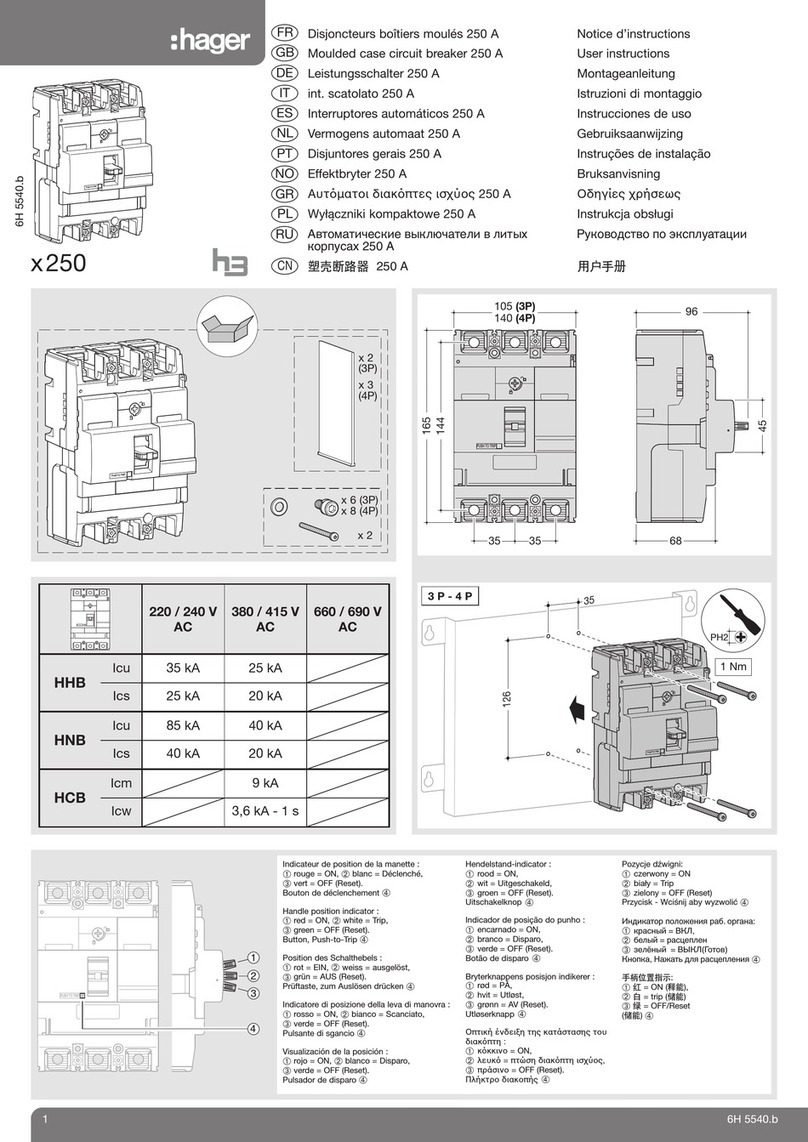
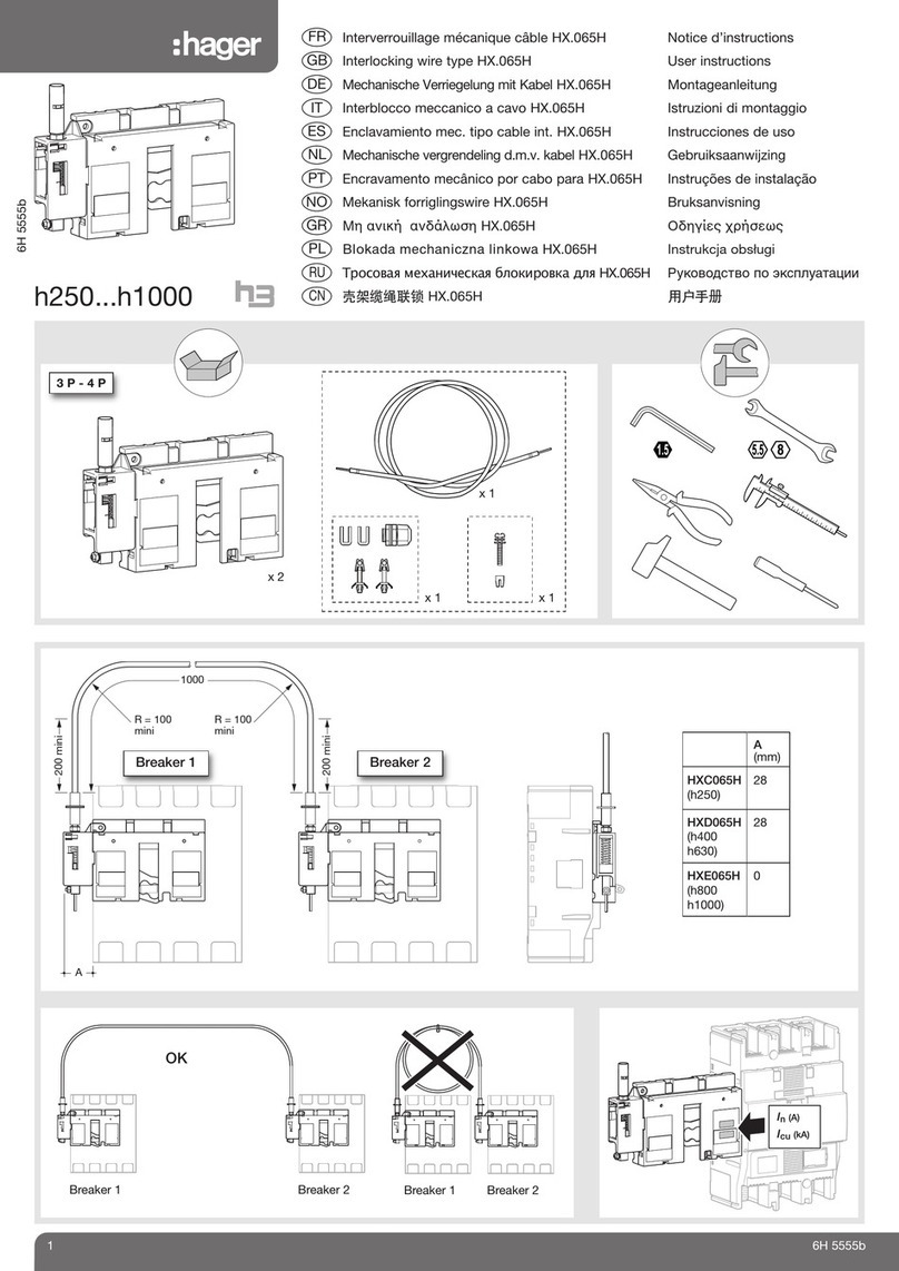
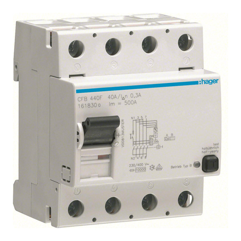
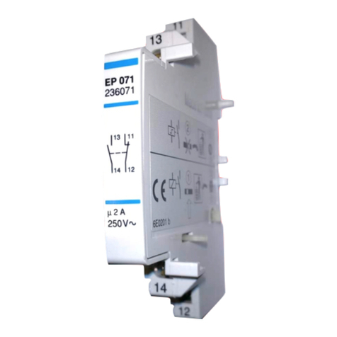
  9. hager WUT10N Installation instructions

hager WUT10N Installation instructions

1 Hager Controls S.A.S., 33 rue Saint-Nicolas, B.P. 10140, 67703 SAVERNE CEDEX, France - www.hager.com
6LE000492A
WUT10N
KNX Tastsensor-Modul 1fach/
2 Tasten mit integr. Busankoppler
KNX push-button module
1gang/2 buttons with integr. bus
application unit
Module du bouton poussoir 2
touches avec coupleur de bus
intégré
WUT20N
KNX Tastsensor-Modul 2fach/
4 Tasten mit integr. Busankoppler
KNX push-button module
2gang/4 buttons with integr. bus
application unit
Module du bouton poussoir 4
touches avec coupleur de bus
intégré
e
z
a
06/2015 - 6LE000492A
Bn,.:
M
`
Sicherheitshinweise e
Einbau und Montage elektrischer Geräte dürfen
nur durch eine Elektrofachkraft erfolgen. Dabei
sind die geltenden Unfallverhütungsvorschriften
des Landes zu beachten.
Bei Nichtbeachten der Installationshinweise kön-
nen Schäden am Gerät, Brand oder andere Ge-
fahren entstehen.
Bei Installation und Leitungsverlegung die für
SELV-Stromkreise geltenden Vorschriften und
Normen einhalten.
Bei Renovierungsarbeiten das Gerät gegen Ver-
schmutzung durch Farbe, Tapetenkleister, Staub
etc. schützen. Gerät kann beschädigt werden.
Diese Anleitung ist Bestandteil des Produktes
und muss beim Endkunden verbleiben.
Geräteaufbau
Bild 1: Geräteaufbau
(1) Tast-Abdeckung mit Linse (nicht im Lieferumfang)
(2) Tastsensor-Modul
(3) Befestigungsklammern
(4) Rahmen (nicht im Lieferumfang)
(5) Tragring mit Krallenbefestigung
(6) Schraube für Demontageschutz
(7) Status-LEDs
Funktion
Systeminformationen
Dieses Gerät ist ein Produkt des KNX-Systems und
entspricht den KNX-Richtlinien. Detaillierte Fach-
kenntnisse durch KNX-Schulungen werden zum
Verständnis vorausgesetzt. Planung, Installation und
Inbetriebnahme erfolgen mit Hilfe einer KNX-zertifi -
zierten Software.
system link Inbetriebnahme
Die Funktion des Gerätes ist softwareabhängig. Die
Software ist der Produktdatenbank zu entnehmen.
Produktdatenbank, technische Beschreibungen sowie
Konvertierungs- und weitere Hilfsprogramme fi nden
Sie stets aktuell auf unserer Internet-Seite.
easy link Inbetriebnahme
Die Funktion des Gerätes ist konfi gurationsabhängig.
Die Konfi guration kann auch mit Hilfe von speziell für
die einfache Einstellung und Inbetriebnahme entwi-
ckelter Geräte erfolgen.
Diese Art der Konfi guration ist nur mit Geräten des
easy link Systems möglich. easy link steht für eine
einfache, visuell unterstützte Inbetriebnahme. Hierbei
werden vorkonfi gurierte Standard-Funktionen mit
Hilfe eines Service-Moduls den Ein-/Ausgängen
zugeordnet.
Bestimmungsgemäßer Gebrauch
- Bedienen von Verbrauchern, z. B. Licht EIN/AUS,
Dimmen, Jalousie AUF/AB, Speichern und Aufru-
fen von Lichtszenen etc.
- Montage in Gerätedose nach DIN 49073
Produkteigenschaften
- Inbetriebnahme und Programmierung in S-Mode
und E-Mode
- Tastsensor-Funktionen: Schalten/Dimmen, Jalou-
siesteuerung, Wertgeber, Szenenaufruf, Vorgabe
der Heizungsbetriebsart, Zwangssteuerung, Stu-
fenschalter und Vergleicher-Funktion
- Eine Status-LED je Wippe
- Status-LEDs für das Gerät in Funktion und Farbe
parametrierbar
- Integrierter Busankoppler
Bedienung
Das Auslösen von Funktionen und Steuern von elek-
trischen Verbrauchern erfolgt über die Tastbereiche
(Bild 2, gestrichelt) und ist für jedes Gerät individuell
konfi gurierbar.
Zwei Bedienarten sind zu unterscheiden:
- Einfl ächenbedienung:
Das Ein-/Ausschalten oder heller/dunkler Dimmen,
z. B. einer Beleuchtung, erfolgt abwechselnd durch
wiederholtes Betätigen eines Tastbereiches.
- Zweifl ächenbedienung:
Zwei übereinander liegende Tastbereiche bilden
ein Funktionspaar. Betätigen oben z. B. schaltet/
dimmt eine Beleuchtung ein/heller, Betätigen unten
schaltet/dimmt eine Beleuchtung aus/dunkler.
Funktion oder Verbraucher bedienen
Die Bedienung von Verbrauchern, wie Beleuchtung,
Jalousie etc., erfolgt über die Tastfl ächen und hängt
von der Konfi guration des Gerätes ab.
Einen Tastbereich betätigen.
Die hinterlegte Funktion wird ausgeführt.
Der Betätigungsimpuls liegt für die Dauer der
Betätigung an. Funktionsabhängig können kurze
und lange Betätigungen unterschiedliche Aktionen
auslösen, z. B. Schalten/Dimmen.
P
(1)
(2) (3)
(4)
(5)
(6)
(7)
1
2
Safety instructions z
Electrical equipment may only be installed and
assembled by a qualifi ed electrician. Always fol-
low the relevant accident prevention regulations
of the country.
Failure to comply with these installation instruc-
tions may result in damage to the device, fi re or
other hazards.
When installing and laying cables, always comply
with the applicable regulations and standards for
SELV electrical circuits.
During renovation work, protect the device from
pollution by paint, wallpaper paste, dust etc. The
device can be damaged.
These instructions are an integral component of
the product and must be retained by the end us-
er.
Design and layout of the device
Figure 1: Design and layout of the device
(1) Touch cover (not within scope of delivery)
(2) Push-button module
(3) Fastening clamps
(4) Frame (not within scope of delivery)
(5) Supporting ring with prong connection
(6) Screw for dismantling protection
(7) Status LEDs
Function
System information
This device is a product of KNX system and corre-
sponds to the KNX guidelines. Detailed specialised
knowledge obtained from KNX training courses
is required for comprehension. The planning, installa-
tion and commissioning are carried out with the help
of KNX-certifi ed software.
system link start-up
The function of the device is software-dependent. The
software is to be taken from the product database. You
can fi nd the latest version of the product database,
technical descriptions as well as conversion and addi-
tional support programmes on our website.
easy link start-up
The function of the device is confi guration-dependent.
The confi guration can also be done using devices devel-
oped specially for simple setting and start-up.
This type of confi guration is only possible with devic-
es of the easy link system. easy link stands for easy,
visually supported start-up. Preconfi gured standard
functions are assigned to the in/outputs by means of
a service module.
Correct use
- Operation of consumers, e.g. light on/off, dim-
ming, blind up/down, saving and opening light
scenes, etc.
- Installation into wall box according to DIN 49073
Product characteristics
- Start-up and programming in S-mode and E-mode
- Push-button functions: switching/dimming, blind
control, value transmitter, scene call-up, specifi ca-
tion of the heating operating mode, forced control,
stepping switch and comparator function
- One status LED per rocker
- Function and colour of the status LEDs confi gur-
able for the device
- Integrated bus coupling unit
Operation
Triggering of functions and operation of electrical
loads takes place via touch surfaces (fi gure 2,
dashed) and can be set individually for each device.
There are two operating modes:
- Single-surface operation:
Switching lighting on/off and dimming brighter/
darker is carried out alternately by repeated
touching of a touch surface.
- Two-surface operation:
Two superimposed touch surfaces form a function
pair. For example, touching the top surface switch-
es/dims lighting on/makes it brighter, touching the
bottom surface switches it off/makes it darker.
Operating a function or load
Consumers, such as lighting, blinds, etc., are operat-
ed using the touch surfaces, which are dependent on
the device confi guration.
Touch a touch surface.
The stored function is executed.
The actuation pulse lasts for the duration of the
actuation. Depending on the function, short and
long touches can trigger different actions, e.g.
switching/dimming.
P
Consignes de sécurité a
L‘installation et le montage d‘appareils élec-
triques doivent être effectués uniquement par un
électricien qualifi é. Les prescriptions de préven-
tion des accidents en vigueur dans votre pays
doivent être respectées.
Le non-respect des consignes d‘installation peut
entraîner des dommages sur l‘appareil, un incen-
die ou présenter d‘autres dangers.
Veuillez observer les prescriptions et les normes
en vigueur pour les circuits électriques TBTS lors
de l‘installation et de la pose des câbles.
En cas de travaux de rénovation, veuillez proté-
ger l‘appareil contre la peinture, les colles de pa-
pier peint, la poussière etc.. L’appareil risque
d’être endommagé.
Ce mode d‘emploi fait partie intégrante du pro-
duit et doit être conservé par l‘utilisateur fi nal.
Composition de l’appareil
Image 1: Description de l‘appareil
(1) Enjoliveur avec voyant (non fourni)
(2) Mécanisme du bouton poussoir
(3) Clips de fi xation
(4) Plaque décorative (non fourni)
(5) Support avec fi xation à griffes
(6) Vis antivol
(7) LED d‘état
Fonction
Informations système
Cet appareil est un produit du système KNX et est
conforme au standard KNX. Des connaissances spé-
cialisées détaillées dispensées par le biais de forma-
tions KNX sont nécessaires pour la compréhension du
système. La programmation, l‘installation et la mise en
service s‘effectuent à l‘aide d‘un logiciel certifi é KNX.
Mise en service system link
Les fonctions précises de ces produits dépendent
de la confi guration et du paramétrage. Le logiciel
d‘application est disponible dans la base de données
produits. La base de données produit, les descrip-
tions techniques, les programmes de conversion
ainsi que d‘autres logiciels d‘assistance à jour sont
disponibles sur notre site Internet.
Mise en service easy link
Les fonctions précises de ces produits dépendent de la
confi guration et du paramétrage. La confi guration peut
être réalisée par un outil de confi guration dédié qui per-
met un paramétrage et une mise en œuvre simplifi és.
Cette méthode de confi guration ne peut être utilisée
qu‘avec des produits compatibles easy link. La méthode
de confi guration easy link permet, au travers d‘une inter-
face graphique, une mise en œuvre simplifi ée. Ainsi, des
fonctions de bases pré-confi gurées sont affectées aux
entrées et aux sorties via l‘outil de confi guration.
Cas d‘usage typique
- Exemples d’application ; MARCHE/ARRÊT de la
lumière, variation, OUVERTURE/FERMETURE
des stores, sauvegarde et appel des scénarios
d‘éclairage etc.
- Montage dans une boîte d‘encastrement confor-
mement à DIN 49073
Caractéristiques du produit
- Mise en service et programmation en system link
et easy link
- Fonctions du bloc boutons poussoirs: commutation/
variation, commande des stores, transmetteur de
valeur, appel de scènes, détermination du mode de
fonctionnement du chauffage, commande forcée,
commutateur à plots et fonction comparateur
- Une LED d‘état par touche
- LED d‘état pour l‘appareil, fonctions et couleurs
paramétrables
- Coupleur de bus intégré
Fonctionnement
L’émission des fonctions et la commande des
charges électriques se font via les boutons poussoirs
(image 2, en pointillés) et il est possible de les confi -
gurer individuellement pour chaque appareil.
Il faut faire la différence entre les deux types de
commande:
- Commande mono bouton:
L‘activation / la désactivation de l‘éclairage ou la
variation (plus clair/plus foncé) par ex. s‘effec-
tue(nt) par alternance en appuyant successive-
ment sur un bouton poussoir.
- Commande avec 2 boutons:
Deux boutons poussoirs (un supérieur et un infé-
rieur) forment une paire fonctionnelle. Appuyer sur
la partie supérieure pour allumer/régler un éclairage
plus clair; appuyer sur la partie inférieure pour
éteindre/régler un éclairage plus sombre.
Utilisation de la fonction ou de la charge
L‘utilisation de charges telles que l‘éclairage, les
stores, etc. s‘effectue grâce aux boutons poussoirs et
dépend de la programmation de l‘appareil.
Appuyer sur un bouton poussoir.
La fonction mémorisée est exécutée.
L‘impulsion activant la fonction ne dure que le temps
de l’appuis sur le bouton. Selon les fonctions, un
appui court ou prolongé peut provoquer des actions
différentes, comme par ex. commuter/varier la lumi-
nosité.
P
2 Hager Controls S.A.S., 33 rue Saint-Nicolas, B.P. 10140, 67703 SAVERNE CEDEX, France - www.hager.com 06/2015 - 6LE000492A
Informationen für die Elektrofachkraft e
Montage und elektrischer Anschluss
GEFAHR!
Elektrischer Schlag bei Berühren
spannungsführender Teile in der Ein-
bauumgebung.
Elektrischer Schlag kann zum Tod
führen!
Vor Arbeiten am Gerät Anschlusslei-
tungen freischalten und spannungsfüh-
rende Teile in der Umgebung abdecken!
ç
Gerät anschließen und montieren
Den Tragring (5) lagerichtig auf eine Gerätedose
montieren.
Busleitung mit Anschlussklemme durch den
Rahmen (4) führen und auf der Rückseite an das
Tastsensor-Modul (2) anschließen.
Tastsensor-Modul (2) mit Rahmen (4) auf den
Tragring stecken bis die Befestigungsklammern
(3) einrasten.
Demontageschutz mit Schraube (6) herstellen,
wenn erwünscht.
Tast-Abdeckung (1) auf Tastsensor-Modul (2)
wieder aufstecken.
Demontage
Tast-Abdeckung (1) vom Tastsensor-Modul (2)
abziehen.
Schraube für Demontageschutz (6) lösen.
Tastsensor-Modul (2) vom Tragring abziehen.
Designrahmen dabei festhalten.
Inbetriebnahme
Das Gerät ist angeschlossen und betriebsbereit.
Es wird allgemein die folgende Vorgehensweise
empfohlen.
system link - Physikalische Adresse und
Anwendungssoftware laden (Bild 3)
(8) Programmier-Taste
(9) Programmier-LED
Die physikalische Adresse wird immer nur für ein
Gerät vergeben. Es darf sich immer nur ein Gerät
im Programmiermodus befi nden.
Es wird empfohlen, die physikalische Adresse vor
der Montage zu programmieren.
Falls vorhanden die Tast-Abdeckung über der
Programmier-Taste (8) lösen.
Busspannung einschalten.
Programmier-Taste (8) drücken.
Die Programmier-LED (9) leuchtet.
Leuchtet die Programmier-LED nicht, liegt keine
Busspannung an.
Physikalische Adresse in das Gerät laden.
Die Beleuchtung der Programmier-LED erlischt.
Anwendungssoftware laden. Physikalische Adres-
se auf Beschriftungsfeld notieren.
Das Laden einer nicht kompatiblen Anwendungs-
software wird durch Blinken der Status-LEDs (7)
angezeigt.
Tast-Abdeckung wieder aufstecken.
easy link
Informationen zur Anlagen-Konfi guration sind der
ausführlichen Beschreibung des Service-Moduls
easy link zu entnehmen.
Anhang
Technische Daten
KNX Medium TP 1
Inbetriebnahmemodus system link, easy link
Nennspannung KNX DC 21 … 32 V SELV
Stromaufnahme KNX typ. 10 mA
Anschlussart KNX Busanschlussklemmen
Abmessung (B x H x T) 71 x 71 x 32 mm
Klemmbereich Befestigungskrallen 52 … 70 mm
Aufbauhöhe ab Tragring 11 mm
Schutzart IP20
Schutzklasse III
Betriebstemperatur -5 … +45 °C
Lager-/ Transporttemperatur -20 … +70 °C
Normen EN 60669-2-1; EN 60669-1
EN 50428
Hilfe im Problemfall
Busbetrieb nicht möglich.
Ursache: Busspannung liegt nicht an.
Busanschlussklemmen auf richtige Polung über-
prüfen.
Busspannung durch kurzes Drücken der Program-
mier-Taste (8) überprüfen, rote Programmier-LED
(9) leuchtet bei anliegender Busspannung.
Zubehör
Tast-Abdeckung 1fach mit Linse WYA86x
Tast-Abdeckung 2fach mit Linse WYA89x
P
P
P
P
Information for electricians z
Installation and electrical connection
DANGER!
Touching live parts in the installation
environment can result in an electric
shock.
An electric shock can be lethal!
Disconnect the connecting cables
before working on the device and cover
all live parts in the area!
ç
Connecting and installing the device
Mount the supporting ring (5) to a wall box in the
correct position.
Run the bus cable with the connecting termi-
nal through the frame (4) and connect it to the
push-button module (2) at the back.
Attach the push-button module (2) with the frame
(4) to the supporting ring until the fastening brack-
ets (3) engage.
Fix dismantling protection with screw (6) if desired.
Reattach touch cover (1) to push-button module (2).
Dismantling
Remove touch cover (1) from push-button module
(2).
Loosen screw for dismantling protection (6).
Remove push-button module (2) from supporting
ring. Hold on to design frame.
Start-up
The device is connected and ready for operation. In
general the following procedure is recommended.
system link - Loading the physical address and
application software (fi gure 3)
(8) Programming button
(9) Programming LED
The physical address is only ever assigned for
one device. Only one device can ever be in pro-
gramming mode.
It is advisable to program the physical address
before installation.
If available, release the touch cover using the
programming button (8).
Switch on bus voltage.
Press programming button (8).
The programming LED (9) lights up.
If the programming LED does not light up, no bus
voltage is present.
Load the physical address into the device.
The programming LED goes out.
Load application software Note down the physical
address on the labelling fi eld.
The loading of non-compatible application software
is indicated by fl ashing of the status LEDs (7).
Reattach the touch cover.
easy link
Information on the system confi guration can be taken
from the extensive description of the service module
easy link.
Appendix
Technical data
KNX Medium TP 1
Start-up mode system link, easy link
Rated voltage KNX DC 21 … 32 V SELV
Current consumption KNX typ. 10 mA
Connection mode KNX bus connecting terminals
Dimensions (W x H x D) 71 x 71 x 32 mm
Clamping range of attachment claws 52 … 70 mm
assembling height from supporting ring 11 mm
Degree of protection IP 20
Protection class III
Operating temperature -5 … +45 °C
Storage/transport temperature -20 … +70 °C
Standards EN 60669-2-1; EN 60669-1
EN 50428
Troubleshooting
Bus operation is not possible.
Cause: Bus voltage is not present.
Check bus connection terminals for correct
polarity.
Check bus voltage by briefl y pressing the pro-
gramming button (8), red programming LED (9)
lights up if bus voltage is present.
Accessories
Touch cover 1gang with lens WYA86x
Touch cover 2gang with lens WYA89x
P
P
P
P
Informations destinées aux a
électriciens
Montage et branchement électrique
DANGER!
Choc électrique en cas de contact
avec les pièces sous tension dans
l'environnement de l'installation.
Un choc électrique peut entraîner la
mort!
Avant d'intervenir sur l'appareil, mettre
l'installation hors tension et recouvrir
les pièces conductrices avoisinantes!
ç
Raccordement et montage de l‘appareil
Monter le support (5) en bonne position sur une
boîte d‘encastrement.
Passer le câble bus avec la borne de raccor-
dement dans la plaque de raccordement (4) et
le raccorder sur la partie arrière du module de
bouton poussoir (2).
Insérer le module de bouton poussoir (2) avec la
plaque de recouvrement (4) sur le support jusqu‘à
ce que les clips de fi xation (3) soient verrouillés.
Verrouiller l‘ensemble à l‘aide de la vis antivol (6)
si besoin.
Mettre en place l‘enjoliveur (1) sur le le module du
bouton poussoir (2).
Démontage
Retirer l‘enjoliveur (1) du module bouton poussoir (2).
Desserrer la vis antivol (6).
Retirer le module du bouton poussoir (2) du sup-
port. Bien maintenir la plaque décorative.
Mise en service
L‘appareillage est raccordé et prêt à fonctionner.
Nous vous recommandons de procéder de la ma-
nière suivante.
system link - Charger l‘adresse physique et le
logiciel d‘application (Image 3)
(8) Bouton poussoir d‘adressage physique
(9) LED d’adressage physique
L‘adresse physique n‘est attribuée que pour un
appareil. Un seul appareil doit se trouver en mode
de programmation.
Il est recommandé de télécharger l‘adresse phy-
sique avant de procéder au montage.
Le cas échéant, enlever l‘enjoliveur situé au-des-
sus du bouton poussoir d’adressage physique (8)
Mettre sous tension l‘alimentation bus.
Appuyer sur le bouton poussoir d‘adressage
physique (8).
La LED d‘adressage physique (9) s‘allume.
Si la LED d’adressage physique ne s‘allume pas,
la tension bus est absente.
Charger l‘adresse physique dans l‘appareil.
La LED d‘adressage physique s‘éteint.
Télécharger le logiciel d‘application. Noter
l‘adresse physique sur l‘appareil.
Le chargement d‘un logiciel d‘application incom-
patible vous sera signalé par le clignotement des
LED d‘état (7).
Remettre en place l‘enjoliveur.
easy link
Veuillez-vous référer à la description détaillée du
module de service easy link pour obtenir des infor-
mations sur la confi guration de l‘installation.
Annexes
Caractéristiques techniques
Média de communication KNX TP 1
Mode de mise en service system link, easy link
Tension nominale KNX DC 21 … 32 V TBTS
Courant absorbé KNX typ. 10 mA
Type de raccordement KNX Bornes de
raccordement de bus
Dimensions (I x H x P) 71 x 71 x 32 mm
Zone de serrage pinces de fi xation 52 … 70 mm
Hauteur de montage à partir du support 11 mm
Indice de protection IP20
Classe de protection III
Température de fonctionnement -5 … +45 °C
Température de stockage/transport -20 … +70 °C
Normes EN 60669-2-1; EN 60669-1
EN 50428
Que faire si
Pas de communication bus.
Cause :Tension bus absente.
Vérifi er la bonne polarité des bornes de raccorde-
ment du bus.
Vérifi er la tension de bus en appuyant brièvement
sur le bouton poussoir d‘adressage physique (8),
l‘allumage du LED d‘adressage physique rouge
(9) indique la présence bus.
Accessoires
Enjoliveur pour
poussoir 2 touches avec voyant WYA86x
Enjoliveur pour
poussoir 4 touches avec voyant WYA89x
P
P
P
P
(8)(9)
3

This manual suits for next models

1

Other hager Circuit Breaker manuals

hager K14 Series User manual

hager

hager K14 Series User manual

hager TR521 User manual

hager

hager TR521 User manual

hager Quadro 4 FC110 User manual

hager

hager Quadro 4 FC110 User manual

hager TN003 User manual

hager

hager TN003 User manual

hager hw+ User manual

hager

hager hw+ User manual

hager EP 071 User manual

hager

hager EP 071 User manual

hager XEVS400 Operating and safety instructions

hager

hager XEVS400 Operating and safety instructions

hager hw+ User manual

hager

hager hw+ User manual

hager CEA263U User manual

hager

hager CEA263U User manual

hager TYFS130 User manual

hager

hager TYFS130 User manual

hager Invicta 3 JF8 B Series User manual

hager

hager Invicta 3 JF8 B Series User manual

hager VE24AH User manual

hager

hager VE24AH User manual

hager CE480U User manual

hager

hager CE480U User manual

hager h3 x160 Series User manual

hager

hager h3 x160 Series User manual

hager h3 x160 User manual

hager

hager h3 x160 User manual

hager TS 303 Installation instructions

hager

hager TS 303 Installation instructions

hager XEVS120 Operating and safety instructions

hager

hager XEVS120 Operating and safety instructions

hager New VegaD User manual

hager

hager New VegaD User manual

hager HX 830 User manual

hager

hager HX 830 User manual

hager h3 HED400G User manual

hager

hager h3 HED400G User manual

hager h250 User manual

hager

hager h250 User manual

hager C B Series User manual

hager

hager C B Series User manual

hager h 160 H User manual

hager

hager h 160 H User manual

hager h3+ Use and care manual

hager

hager h3+ Use and care manual

Popular Circuit Breaker manuals by other brands

Siemens 3VA9601-0WF30 manual

Siemens

Siemens 3VA9601-0WF30 manual

Siemens 3VT9500-4WA30 operating instructions

Siemens

Siemens 3VT9500-4WA30 operating instructions

Acrel ASCB1 Series Installation and operation manual

Acrel

Acrel ASCB1 Series Installation and operation manual

OEZ 3VA9-RS-4VBH1 Installation, service and maintenance instructions

OEZ

OEZ 3VA9-RS-4VBH1 Installation, service and maintenance instructions

Eaton Series NRX Instruction leaflet

Eaton

Eaton Series NRX Instruction leaflet

nader NDM3 Series product manual

nader

nader NDM3 Series product manual

Huayi LW36A-126 operation instruction

Huayi

Huayi LW36A-126 operation instruction

Delixi NAVIGATOR Series user manual

Delixi

Delixi NAVIGATOR Series user manual

LEGRAND Enedis DPX 3 250AB manual

LEGRAND

LEGRAND Enedis DPX 3 250AB manual

ETI ETITEC B T12 installation instructions

ETI

ETI ETITEC B T12 installation instructions

Eaton LS-S ZBZ Series operating instructions

Eaton

Eaton LS-S ZBZ Series operating instructions

Circutor RECmax Lpd instruction manual

Circutor

Circutor RECmax Lpd instruction manual

OEZ LMF Instructions for use

OEZ

OEZ LMF Instructions for use

Projoy Electric PEBS-S Instructions for installation and operation

Projoy Electric

Projoy Electric PEBS-S Instructions for installation and operation

Hubbel CIRCUIT- LOCK HBLDS3SSP General information

Hubbel

Hubbel CIRCUIT- LOCK HBLDS3SSP General information

Eaton DILM185-S installation instructions

Eaton

Eaton DILM185-S installation instructions

Schrack BES0 Series operating instructions

Schrack

Schrack BES0 Series operating instructions

Siemens 3VA23 H Series operating instructions

Siemens

Siemens 3VA23 H Series operating instructions

manuals.online logo
manuals.online logoBrands
  • About & Mission
  • Contact us
  • Privacy Policy
  • Terms and Conditions

Copyright 2025 Manuals.Online. All Rights Reserved.