Federal Signal Corporation Pathfinder PF100 User manual

Installation and
Maintenance Instructions
25500463
C1 1120
Printed in U.S.A.
© Copyright 2018-2020 Federal Signal Corporation
Pathnder®

All product names or trademarks are properties of their respective owners.
Limited Warranty
This product is subject to and covered by a limited warranty,
a copy of which can be found at www.fedsig.com/SSG-Warranty.
A copy of this limited warranty can also be obtained by written
request to Federal Signal Corporation, 2645 Federal Signal Drive,
University Park, IL 60484, email to info@fedsig.com or
call +1 708-534-3400.
This limited warranty is in lieu of all other warranties, express or
implied, contractual or statutory, including, but not limited to the
warranty of merchantability, warranty of fitness for a particular
purpose and any warranty against failure of its essential purpose.
2645 Federal Signal Drive
University Park, Illinois 60484
www.fedsig.com
Customer Support
Police/Fire-EMS: 800-264-3578 • +1 708 534-3400
Work Truck: 800-824-0254 • +1 708 534-3400
Technical Support 800-433-9132 • +1 708 534-3400

Pathnder®
Federal Signal www.fedsig.com 3
Contents
Safety Messages for Installers and Operators ................................................................................5
Safety Messages to Installers of Sound/Light Systems .................................................................................. 5
Safety Messages to Operators of Sound/Light Systems.................................................................................8
An Overview of the Pathnder® ..............................................................................................................................................10
Siren, PA, and Speakers .........................................................................................................................................10
Light Bars and SignalMaster®Control.................................................................................................................10
FS Vehicle Integration ............................................................................................................................................. 11
Programmable Solid-State Auxiliary Relays ....................................................................................................... 11
Programmable Input Circuits.................................................................................................................................. 11
LED Indicators and Visual Diagnostics................................................................................................................ 11
System Specifications .............................................................................................................................................. 11
Siren Specifications .................................................................................................................................................12
Relay Specifications.................................................................................................................................................12
Pathfinder Kit Contents........................................................................................................................................... 13
Wiring the Pathnder® .................................................................................................................................16
General Guidelines for Wiring the Pathfinder on a Vehicle ..........................................................................16
Overview of the Pathfinder Connections...........................................................................................................19
Convergence Network Ports ...........................................................................................................19
Relay Outputs.......................................................................................................................................19
General Purpose Inputs.....................................................................................................................19
Park Input ..............................................................................................................................................19
Horn Ring Transfer.............................................................................................................................20
Speaker Connections ........................................................................................................................21
Speaker Diagnostics ..........................................................................................................................21
Radio Re-Broadcast............................................................................................................................21
FS Vehicle Integration........................................................................................................................21
Ignition Input.........................................................................................................................................21
System Power .....................................................................................................................................22
Mounting the Pathnder ..................................................................................................................23
Mounting the Siren ................................................................................................................................................25
Mounting the Control Head (PF 100R and PF200R) ......................................................................................25
Testing the Pathnder® Installation ...............................................................................................27
Horn Ring Operation ..............................................................................................................................................29
Control Head Legends and Safety Messages ................................................................................30
Distributing the Safety Message Card ............................................................................................................... 31
Applying the Siren Safety Labels in the Vehicle ............................................................................................. 31

Pathnder®
Federal Signal www.fedsig.com
4
Safety Messages ..............................................................................................................................32
Safety Messages to Personnel Servicing Federal Electronic Sirens......................................................... 32
Servicing the Pathnder ..................................................................................................................33
Replacing the Slide Switch .................................................................................................................................. 33
Getting Technical Support and Service ..........................................................................................35
Getting Repair Service ........................................................................................................................................... 35
Figures
Figure 1 100W Single Tone and 200W Dual Tone Siren Connections............................................................ 17
Figure 2 100W Siren with Integrated Rumbler®.................................................................................................... 18
Figure 3 Battery Connections...................................................................................................................................22
Figure 4 Pathfinder Dimensions............................................................................................................................... 24
Figure 5 Mounting Hardware Dimensions ............................................................................................................ 24
Figure 6 Bail Bracket Assembly ...............................................................................................................................25
Figure 7 Bracket Attached to Back of Control Head ..........................................................................................26
Figure 8 Brackets Attached to Control Head and Mounting Surface ............................................................26
Figure 9 Pathfinder Default Programming............................................................................................................. 27
Figure 10 Installing the Control Head Labels........................................................................................................30
Figure 11 Safety Message Card (left) and Siren Safety Labels (right)............................................................... 31
Figure 12 Keypad Removal ........................................................................................................................................ 33
Figure 13 Slide Switch Replacement....................................................................................................................... 34
Tables
Table 1 System Specifications.................................................................................................................................... 11
Table 2 Siren Specifications...................................................................................................................................... 12
Table 3 Relay Specifications .....................................................................................................................................12
Table 4 PF100 and PF200 Kit Contents ................................................................................................................. 13
Table 5 PF100R and PF200R Kit Contents............................................................................................................ 14
Table 6 PF200-RM Kit Contents............................................................................................................................... 15
Table 7 Pathfinder®Switch Default Programming ..............................................................................................28
Table 8 Pathfinder Button Default Programming................................................................................................28
Table 9 Pathfinder Input Default Programming...................................................................................................29
Table 10 Service Parts................................................................................................................................................ 35

Safety Messages for Installers and Operators
5
Installation and Maintenance Instructions
Federal Signal www.fedsig.com
Safety Messages for Installers and Operators
For your safety, read and understand this manual thoroughly before installing,
operating, and servicing the Pathfinder siren amplifier/relay module. The safety
messages presented in this chapter and throughout the manual are reminders to
exercise extreme care at all times. Read and understand the safety instructions to
installers (doc. no. 256A692), and keep it close at hand for reference.
To download copies of this manual, go to www.fedsig.com or call the Federal
Signal Service Department at 1-800-433-9132 (708-534-3400) 7 a.m. to 5 p.m.,
Monday through Friday (CT).
Safety Messages to Installers of Sound/Light Systems
People’s lives depend on your proper installation and servicing of Federal Signal
products. It is important to read and follow all instructions shipped with this
product. Listed below are some other important safety instructions and precautions
you should follow:
Before Installation
Qualifications
• To properly install an electronic siren, you must have a good understanding
of automotive electrical procedures and systems, along with proficiency in
the installation and service of safety warning equipment. Always refer to
the vehicle’s service manuals when performing equipment installations on a
vehicle.
Sound Hazards
• Your hearing and the hearing of others, in or close to your emergency vehicle,
could be damaged by loud sounds. This can occur from short exposures to very
loud sounds, or from longer exposures to moderately loud sounds. For hearing
conservation guidance, refer to federal, state, or local recommendations. OSHA
Standard 1910.95 oers guidance on “Permissible Noise Exposure.”
• All eective sirens and horns produce loud sounds (120 dB) that may cause
permanent hearing loss. Always minimize your exposure to siren sound and
wear hearing protection. Do not sound the siren indoors or in enclosed areas
where you and others will be exposed to the sound.
• Federal Signal siren amplifier/relay modules and speakers are designed to
work together as a system. Combining a siren and speaker from dierent
manufacturers may reduce the warning eectiveness of the siren system and
may damage the components. Verify or test your combination to make sure the
system works together properly and meets federal, state, and local standards
or guidelines.

Pathnder®
Federal Signal www.fedsig.com
Safety Messages for Installers and Operators
6
During Installation
• Do NOT get metal shavings inside the product. Metal shavings in the product
can cause the system to fail. If drilling must be done near the unit, place an
ESD-approved cover over the unit to prevent metal shavings from entering
the unit. Inspect the unit after mounting to ensure that there are no shavings
present in or near the unit.
• Do NOT connect this system to the vehicle battery until ALL other electrical
connections are made, mounting of all components is complete, and you have
verified that no shorts exist. If wiring is shorted to vehicle frame, high current
conductors can cause hazardous sparks, resulting in electrical fires or flying
molten metal.
• Ensure that the siren amplifier/relay module and speaker(s) in your installation
have compatible wattage ratings.
• In order for the electronic siren to function properly, the ground connection
must be made to the NEGATIVE battery terminal.
• Sound output will be severely reduced if any objects are in front of the speaker.
If maximum sound output is required for your application, ensure that the front
of the speaker is clear of any obstructions.
• Install the speaker(s) as far forward on the vehicle as possible in a location that
provides maximum signaling eectiveness and minimizes the sound reaching
the vehicle’s occupants. Refer to the National Institute of Justice guide 500-00
for further information.
• Mounting the speakers behind the grille will reduce the sound output and
warning eectiveness of the siren system. Before mounting speakers behind
the grille, make sure the vehicle operators are trained and understand that this
type of installation is less eective for warning others.
• Sound propagation and warning eectiveness will be severely reduced if the
speaker is not facing forward. Carefully follow the installation instructions and
always install the speaker with the projector facing forward.
• Do NOT install the speaker(s) or route the speaker wires where they may
interfere with the operation of airbag sensors.
• Installation of two speakers requires wiring speakers in phase.
• Never attempt to install aftermarket equipment, which connects to the vehicle
wiring, without reviewing a vehicle wiring diagram available from the vehicle
manufacturer. Ensure that your installation will not aect vehicle operation and
safety functions or circuits. Always check vehicle for proper operation after
installation.
• Do NOT install equipment or route wiring or cord in the deployment path of an
airbag.
• If a vehicle seat is temporarily removed, verify with the vehicle manufacturer if
the seat needs to be recalibrated for proper airbag deployment.

Safety Messages for Installers and Operators
7
Installation and Maintenance Instructions
Federal Signal www.fedsig.com
• Locate the control head so the vehicle, controls, and microphone can be
operated safely.
• When drilling into a vehicle structure, ensure that both sides of the surface are
clear of anything that could be damaged. All drilled holes should be deburred
and all sharp edges should be smoothed. All wires going through drilled holes
should be protected by a grommet or convolute/split-loom tubing. All exterior
drilled holes must be sealed with Motorcraft seam sealer T-A-2-B or equivalent
to prevent the potential exposure to carbon monoxide or other potentially
harmful fumes. Failure to observe this warning could cause serious injury or
death.
After Installation
• After installation, test the siren and light system to ensure that it is operating
properly.
• Test all vehicle functions, including horn operation, vehicle safety functions, and
vehicle light systems, to ensure proper operation. Ensure that installation has
not aected vehicle operation or changed any vehicle safety function or circuit.
• After testing is complete, provide a copy of these instructions to the
instructional sta and all operating personnel.
• File these instructions in a safe place and refer to them when maintaining or
reinstalling the product.
Failure to follow all safety precautions and instructions may result in property
damage, serious injury, or death.
RETAIN AND REFER TO THESE MESSAGES

Pathnder®
Federal Signal www.fedsig.com
Safety Messages for Installers and Operators
8
Safety Messages to Operators of Sound/Light Systems
People’s lives depend on your safe operation of Federal Signal products. It is
important to read and follow all instructions shipped with the products. Listed
below are some other important safety instructions and precautions you should
follow:
• Do not attempt to activate or deactivate the light system control while driving in
a hazardous situation.
• Although your warning system is operating properly, it may not be completely
eective. People may not see or heed your warning signal. You must recognize
this fact and continue to drive cautiously.
• Situations may occur that obstruct your warning signal when natural and man-
made objects are between your vehicle and others, such as raising your hood
or trunk lid. If these situations occur, be especially careful.
• All eective sirens and horns produce loud sounds that may cause, in certain
situations, permanent hearing loss. You and your passengers should consider
taking appropriate safety precautions, such as wearing hearing protection.
• In order to be an eective warning device, this product produces bright light
that can be hazardous to your eyesight when viewed at a close range. Do not
stare directly into this lighting product at a close range, or permanent damage
to your eyesight may occur.
• It is important that you fully understand how to safely operate this warning
system before use.
• Operate your vehicle and its light/sound system in accordance with your
department’s Standard Operating Procedures.
• If a selected function does not perform properly or if any of the lamps remain
illuminated when the control is o, disconnect the power connector from the
control unit and contact the nearest service center.
• At the start of your shift, ensure that the entire warning light system and the
siren system is securely attached and operating properly.
• The eectiveness of an interior mounted warning light depends on the clarity,
the tinting, and the angle of the glass it is being placed behind. Tinting, dirt,
defects, and steeply angled glass reduce the light output of the warning light.
This may reduce the eectiveness of the light as a warning signal. If your
vehicle has dirty, tinted, or steeply angled glass, use extra caution when driving
your vehicle or blocking the right of way with your vehicle.
• Suction cup mounting is for temporary applications only. The unit should be
removed from the window and stored securely when not in use. Temperature
changes and sunlight can cause suction cups to lose holding power.
Periodically check the unit to be sure the suction cups have a firm grip on the

Safety Messages for Installers and Operators
9
Installation and Maintenance Instructions
Federal Signal www.fedsig.com
mounting surface. An improperly secured light could fall o of the vehicle,
causing injury and damage.
• The holding power of magnetic mounting systems is dependent upon surface
finish, surface flatness, and thickness of the steel mounting surface. Therefore,
to promote proper magnetic mounting:
• Keep the mounting surface and magnets clean, dry, and free of foreign
particles that prevent good surface contact.
• Ensure that the mounting surface is flat.
• Do not use a magnet mounting system on vehicles with vinyl tops.
• To prevent the light assembly from sliding on mounting surface, avoid quick
acceleration and hard stops.
Failure to follow these precautions may result in property damage, serious injury, or
death.
RETAIN AND REFER TO THESE MESSAGES

Pathnder®
Federal Signal www.fedsig.com
An Overview of the Pathnder®
10
An Overview of the Pathnder®
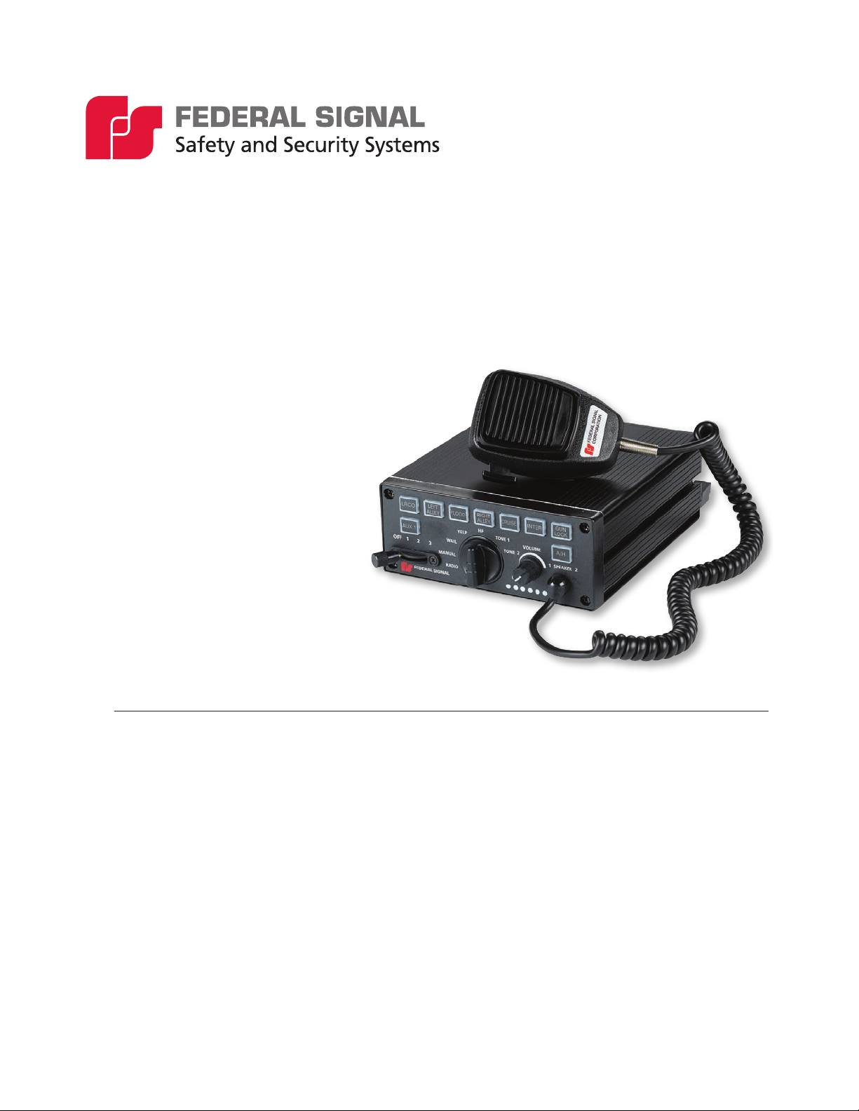
The Pathfinder siren is a full-featured, programmable, electronic siren and light
control system. State-of-the-art microprocessor technology is used to create
a system with a small, compact siren system that can be installed under the
dashboard (Self -Contained), in the trunk, or under the seat (remote) of any vehicle
with a 12 V or 24 V negative ground system. The Pathfinder siren uses class D
amplifier technology without the need for a large and heavy transformer. The
PF200 provides two independent 100 W channels of audio, for a total of 200 W.
The PF100 provides one 100-watt channel.
The module provides the automatic, simultaneous light and siren activation
required by some jurisdictions. A security gun timer is also provided to minimize
the possibility of unauthorized shotgun release. The module has two easily
accessible Convergence Network serial ports that can connect a remote mounted
control head and/or any serially-controlled Federal Signal product. The siren also
has FS Vehicle Integration to allow for various vehicle events to integrate with
siren/lighting control. A variety of system features can be programmed with the
Convergence Network Configuration Software from a computer via a USB cable
that connects the siren amplifier. System features include flash patterns, siren
tones, and momentary, push-on/push-o, timed relay operation, as well as vehicle
events. Programming does not require disassembling or removing any hardware
from the vehicle.
Siren, PA, and Speakers
The Pathfinder produces wail, yelp, priority, and an air horn sound by default. The
horn-ring transfer feature enables the driver to control siren tones by pressing the
horn button. Public address is available with the Federal Signal microphone, which
is included with the system. Radio rebroadcast is also available. The Pathfinder
PF200 can drive one or two 11-ohm impedance, 100-watt speakers. The two
11-ohm impedance, 100-watt speakers have separate wires that allow the
Pathfinder to provide dual siren tones. Alternatively, the Pathfinder can drive one
11-ohm impedance, 100-watt speaker on one channel, and two Rumbler speakers
on the second channel to provide Rumbler integration without the need for a
secondary external amplifier.
The PF100 Pathfinder can drive one 11-ohm impedance, 100-watt speaker.
Light Bars and SignalMaster® Control
Compatible light bars include full featured, serially-controlled Federal Signal
Legend®, Valor®, Allegiant™, Navigator®, and Integrity®, as well as the SpectraLux®
ILS Series of interior-mounted light bars. In addition, flash rates and patterns, light
bar dimming, external SignalMaster control and other options can be programmed
with the Convergence Network Configuration Software.

An Overview of the Pathnder®
11
Installation and Maintenance Instructions
Federal Signal www.fedsig.com
FS Vehicle Integration
The Pathfinder®siren includes the capability to integrate with the existing vehicle
CAN bus. The FS Vehicle Integration uses a vehicle-specific cable (not included) to
seamlessly integrate with the vehicle. Vehicle events can be programmed with the
Convergence Network Configuration Software to interface with the lighting/siren
control. The Convergence Network Configuration Software contains the latest list
of events supported based on model, make and year of the vehicle.
Programmable Solid-State Auxiliary Relays
The Pathfinder PF200 has 12 solid-state relays: five ten-amphere active high
solid-state relays, one ten-amphere high-low and six five-amphere high. The
maximum output current for each relay can be set with the Convergence Network
Configuration Software.
The PF100 version has six solid-state relays: five ten-amphere active high solid-
state relays, and one ten-amphere high-low relay.
Programmable Input Circuits
The Pathfinder has connections for four general purpose input circuits, plus
dedicated inputs for park, horn and ign. Ignition is an active-high only input, while
all other inputs are programmable for active-high or active-low. The inputs are most
commonly used for switches that send a signal to the siren when a condition in the
vehicle changes.
LED Indicators and Visual Diagnostics
All buttons on the control head glow when the system is on. Pressed buttons
turn bright to indicate that the function they control is active. The buttons are
programmable for red or blue backlighting. LEDs on the keypad mimic these active
SignalMaster patterns: Left, Right, Center-Out, and Warn. An LED glows over the
position in which the slide switch is placed. Diagnostic LEDs for speaker fault
detection are also available and are programmable.
System Specications
Table 1 System Specications
Input Voltage 11 Vdc to 28 Vdc
Polarity Negative ground only
Operating Temperature Range -40°C to +80°C (-40°C to +176°C) (all relays at 50% power)
Standby Current Less than 0.1 A
Max Input Current 75 A (siren and relays)
Dimensions:
PF200 (Self Contained Siren)
Height 2.5 in (6.4 cm)
Width 6.0 in (15.2 cm)
Length 8.4 in (21.3 cm)
Net Weight 3.9 lb (1.77 kg)

Pathnder®
Federal Signal www.fedsig.com
An Overview of the Pathnder®
12
Siren Specications
Table 2 Siren Specications
Speakers One or two 100 W, 11-ohm speakers or
One 100 W, 11-ohm speaker and two Rumbler speakers
Operating Current 100 W - One 11-ohm speaker – 8 A
200 W - Two 11-ohm speakers – 16 A
(13.6 V battery, No Relays active)
Frequency Range 182 to 1600 Hz
Nominal Cycle Rate Wail: 12 cycles per minute
Yelp: 180 cycles per minute
Priority: 370 cycles per minute
High-Low: 60 cycles per minute
Nominal Voltage Output 64 V peak-to-peak (siren tones)
Audio Response 300 Hz to 3,000 Hz ± 3 dB
Siren Tone Compliances SAE J1849 JUL89
Relay Specications
Table 3 Relay Specications
Relays 1-5 10 A (active high)
Relays 6 10 A (active high or active low)
Relays 7-12 (PF200 only) 5 A (active high)

An Overview of the Pathnder®
13
Installation and Maintenance Instructions
Federal Signal www.fedsig.com
Pathnder Kit Contents
Tables 4 through 6 list the parts included with the kit. After unpacking the kit,
examine it for damage that may have occurred in transit. If the product has been
damaged, file a claim immediately with the carrier stating the extent of damage.
Carefully check all envelopes, shipping labels, and tags before removing or
destroying them. Ensure all parts in the packing list are included in the shipment.
If any parts are missing, call Federal Signal Customer Support at 1-800-264-3578,
7a.m. to 5 p.m., Monday through Friday, Central Time.
Table 4 PF100 and PF200 Kit Contents
Qty. Description Part Number -
PF100
Part Number -
PF200
1 100 or 100/200-Watt Siren/Light Controller, Self-Cont 862302144-100 862302144
1 Keypad Legend Stickers 8572294 8572294
1Bracket, Bail, Pathnder, Plastic 862303559 862303559
1 RS485 25 ft (7.62 m) Cable Assembly 1751357-02 1751357-02
1Wire Assemby, Relay, Pathnder 17501359 17501359
1Wire Assembly, I/O, Pathnder 17501360 17501360
1 Cable, USB 2.0, A Male to Mini-B 17501813 17501813
1Kit, Hardware, Pathnder 77700765 77700765
Siren Mount Kit Contains:
2 Term, #8, 6 AWG 19001363 19001363
2 Bolt, Carriage, 1/4"-20, SS 7004A020-12 7004A020-12
2 Nut, Ext Keps, 1/4"-20, Stl 7058A005 7058A005
2 Washer, Flat, 1/4-inch 7072A028 7072A028
2 Screw, Pan, Sems, M4 70000451-06 70000451-06
2 Lockwasher, Int Tth, 1/4-inch 7075A016 7075A016

Pathnder®
Federal Signal www.fedsig.com
An Overview of the Pathnder®
14
Table 5 PF100R and PF200R Kit Contents
Qty. Description Part Number -
PF100R
Part Number -
PF200R
1100 or 100/200-Watt Amplier, Pathnder 862302662-100 862302662
1Control Head, Remote, PF200R, Pathnder 862302151 862302151
1 Keypad Legend Stickers 8572294 8572294
1 Dynamic Microphone with Mod 258B577-03 258B577-03
1Bracket, Bail, Pathnder, Plastic 862303559 862303559
2 Bracket, Mtg. Control, Smart 85361065 85361065
1 Cable Assy, RS485, 25ft (7.62 m) 1751357-02 1751357-02
1Wire Assembly, Relay, Pathnder 17501359 17501359
1Wire Assy, I/O, Pathnder 17501360 17501360
1 Cable, USB 2.0, A Male to Mini-B 17501813 17501813
1 Connector, 8P8C RJ45 T Adapter,1F TO 2 13901989 13901989
1 RS485 8-inch Cable Assembly 1751357-06 1751357-06
1Kit, Hardware, Pathnder 77700765 77700765
Siren Mount Kit Contains:
2 Term, #8, 6 AWG 19001363 19001363
2 Bolt, Carriage, 1/4"-20, SS 7004A020-12 7004A020-12
2 Nut, Ext Keps, 1/4"-20, Stl 7058A005 7058A005
2 Washer, Flat, 1/4-inch 7072A028 7072A028
2 Screw, Pan, Sems, M4 70000451-06 70000451-06
2 Lockwasher, Int Tth, 1/4-inch 7075A016 7075A016
1Kit, Hardware, Control Head, Pathnder 77700992 77700992
Control Head Kit Contains:
2 Screw, 6-32, Pan HD, Phil 7000A404-05 7000A404-05
2 Bolt, Carriage, 1/4-20, SS 7004A020-12 7004A020-12
2 Screw, #10 TYP B, Pan Torx, Stl, Blk Zn 7011246-08 7011246-08
2 Washer, Flat, 1/4 7072A028 7072A028
2 Lockwasher, Split Stl #6 Screw 7074A001 7074A001
2 Lockwasher, Ext Tth, 1/4 7075A007 7075A007

An Overview of the Pathnder®
15
Installation and Maintenance Instructions
Federal Signal www.fedsig.com
Table 6 PF200-RM Kit Contents
Qty. Description Part Number
1 100/200-Watt Siren/Light Ctrlr,Rem. Mic 862302144-RM
1 Microphone, Mnct, Series D MNCT-SD
1 Keypad Legends 8572294
1Bracket, Bail, Pathnder, Plastic 862303559
1 Cable Assy, RS485, 25ft 1751357-02
1Wire Assy, Relay, Pathnder 17501359
1Wire Assy, I/O, Pathnder 17501360
1 Cable, USB 2.0, A Male To Mini-B 17501813
1Kit, Hardware, Pathnder 77700765
Contains:
2 Term, #8, 6 AWG 19001363
2 Bolt, Carriage, 1/4"-20, SS 7004A020-12
2 Nut, Ext Keps, 1/4"-20, Stl 7058A005
2 Washer,Flat,1/4-inch 7072A028
2 Screw, Pan, Sems, M4 70000451-06
2 Lockwasher, Int Tth, 1/4-inch 7075A016

Pathnder®
Federal Signal www.fedsig.com
Wiring the Pathnder®
16
Wiring the Pathnder®
General Guidelines for Wiring the Pathnder on a Vehicle
HIGH CURRENT ARCING: Do not connect this system to the vehicle battery
until ALL other electrical connections are made and you have veried that
no shorts exist. High current conductors can cause hazardous sparks or
burning wire, resulting in electrical res.
DRILLING PRECAUTIONS: Before drilling holes, check the area into which
you plan to drill to ensure that you do not damage vehicle components. All
drilled holes should be deburred and all sharp edges should be smoothed.
Additionally, all exterior drilled holes must be sealed with Motorcraft seam
sealer T-A-2-B or equivalent to prevent the potential exposure to carbon
monoxide or other potentially harmful fumes. Failure to observe this
warning could cause serious injury or death.
Before permanently installing the Pathfinder system, plan all wire routings and
select the mounting locations for the siren amplifier/relay module. Read and
understand all instructions included with related equipment before installing
it. Ensure that all wiring is protected from damage during normal operation of
the vehicle and away from any sharp edges and screws. Splice joints should be
soldered or crimped with butt connectors and properly insulated. Splice joints that
will be exposed to the elements should be adequately sealed and insulated. All
wires that are extended should not be a lesser gauge than its original mating wire.
Make sure that connections are easily accessible for assembly and service.

Wiring the Pathnder®
17
Installation and Maintenance Instructions
Federal Signal www.fedsig.com
Figure 1 100W Single Tone and 200W Dual Tone Siren Connections
FS VEHICLE
INTEGRATION*
SW
TO BATTERY
11 OHM, 100 WATT SPEAKER
OMIT IF ONLY
USING 1
SPEAKER
BLUE 20AWG
BROWN 20AWG
BROWN/WHITE 20AWG
BLUE/WHITE 20AWG
TO HORN RING
TO HORN RING SIDE OF CUT WIRE
TO HORN OR HORN RELAY
WHITE/YELLOW 20AWG
WHITE 20AWG
CUT
WIRE
GREEN 20AWG
GREEN/WHITE 20AWG
RADIO
SPEAKER
GROUND -
BATTERY +
SPST RELAY
(INSTALLER-SUPPLIED)
VEHICLE HORNS
STEERING COLUMN
TWO-
WAY
RADIO

Pathnder®
Federal Signal www.fedsig.com
Wiring the Pathnder®
18
Figure 2 100 W Siren with Integrated Rumbler®
FS VEHICLE
INTEGRATION*
BATTERY +
GROUND -
SW
TWO-
WAY
RADIO
TO BATTERY
SPST RELAY
(INSTALLER-SUPPLIED)
11 OHM, 100 WATT SPEAKER
2 RUMBLER SPEAKERS
BLUE 20AWG
BROWN 20AWG
BROWN/WHITE 20AWG
BLUE/WHITE 20AWG
TO HORN RING
TO HORN RING SIDE OF CUT WIRE
TO HORN OR HORN RELAY
WHITE/YELLOW 20AWG
WHITE 20AWG
VEHICLE HORNS
CUT
WIRE
STEERING COLUMN
GREEN 20AWG
GREEN/WHITE 20AWG
RADIO
SPEAKER

Wiring the Pathnder®
19
Installation and Maintenance Instructions
Federal Signal www.fedsig.com
Overview of the Pathnder Connections
To prepare the vehicle for connecting the Convergence Network system:
1. After planning where to route the wires and cables for the system
components — such as Federal Signal warning lights, directional lights, and
speakers — drill the holes for the wiring. Smooth, deburr, and insert a grommet
in the holes.
2. Mount the system components according to the instructions included with each
product.
The next sections describe how to connect and wire each system component to
the siren amplifier/relay module.
Convergence Network Ports
There are two plug-and-play serial ports that communicate on the Federal Signal
Convergence Network. Federal Signal Network devices include exterior mount
light bar, interior mount ILS systems, and remote keypads. For instructions on
mounting network devices, refer to the instructions included with the products.
For instructions on configuring the operation of the devices connected through
the Convergence Network ports, see the Help menu in the Convergence Network
Configuration Software.
Relay Outputs
The Pathfinder®has a total of twelve solid-state relay output available. Relays 1-6
can each provide up to 10 A switched from the battery terminal on the Pathfinder.
Relay 6 can switch both battery (active-high) and ground (active-low). Relays 7-12 (in
PF200 models only) can each provide up to 5 A switched from the battery terminal
on the Pathfinder. Each relay has a software programmable current limit set that
can be set. By default, the current limit setting is disabled. Each relay also can also
be programmed to flash various patterns and dim levels. See the Convergence
Network Configuration Software for all available programming options available for
the Pathfinder relay outputs.
General Purpose Inputs
The Pathfinder has a total of four general purpose inputs available. These inputs
are set to detect active-high (battery) by default. Each input can be programmed
individually to detect an active-high (battery) or active-low (ground). All inputs are
software-configurable options that include siren activation or siren mute, timer
settings, and switch operation. See the Convergence Network Configuration
Software for all available programming options available for the Pathfinder inputs.
Park Input
The park input circuit sends a signal to the siren amplifier/relay module to mute all
siren functions except Air Horn and Manual and shut o any flashing white light in
the light bar when the vehicle transmission is shifted into park. By default, this input
is set to detect active-low (ground). The park input can be programmed to detect
an active-high (battery) or active-low (ground). The functionality of the park wire

Pathnder®
Federal Signal www.fedsig.com
Wiring the Pathnder®
20
(as well as the input polarity) can be configured with the Convergence Network
Configuration Software. If using FS Vehicle Integration to detect the park event,
this wire is not used. Fold and seal.
Horn Ring Transfer
DETERMINE CURRENT FOR HORN: The horn ring transfer circuit of the
siren can switch a maximum of 5 A. Some vehicles do not have a horn
relay and consequently will draw more than 5 A when the vehicle horn is
activated. Consult your vehicle service manual or a qualied mechanic to
determine the current required to activate the horn. If it is less than 5 A,
perform step 3. If it is greater than 5 A, perform steps 4 through 9.
The horn input circuit is desiged to allow siren and lighting control from the vehicle
horn. This input is set to detect active-low (ground) by default. The horn input can
be programmed to detect an active-high (battery) or active-low (ground). The horn
signal event may be available using FS Vehicle Integration, if so, fold and seal the
unused leads.
NOTE: To enable horn-ring control of siren tones, obtain a SPST relay of enough
contact-current capacity to activate the vehicle horn:
1. Cut the wire that connects the switch for the vehicle horn ring to the horn or
horn relay. See Figure 3.
2. Splice the white/yellow wire from the power cable to the horn ring side of the
wire that you cut in step 1.
3. Splice the white wire from the power cable to the horn side of the cut wire.
4. Mount the SPST relay in a suitable location.
5. Connect the horn side of the wire cut in step 1 to the relay-contact terminal.
6. Determine the “sense” of the vehicle’s horn ring activation circuit. Does the
horn circuit require a switched positive (active-high) voltage or switched ground
(active-low) for activation?
7. Connect the switched relay-contact terminal to the positive or negative
potential you determined in step 6.
8. Connect the white wire from the power cable to one end of the relay coil.
9. Connect the other end of the relay coil to the opposite potential of that
connected to the switched relay contact terminal in step 7.
This manual suits for next models
4
Table of contents
Popular Control System manuals by other brands

Chromalox
Chromalox MicroTherm Installation & operation manual

Siemens
Siemens SINUMERIK 840D sl Diagnostics guide

Beckett
Beckett GENISYS 52040 Product sheet

Varifan
Varifan IC-664 installation guide

Murphy
Murphy MURPHYMATIC MC-900 Series Installation and operating manual

Altecnic
Altecnic Matrix Midi 135D Installation, operation & maintenance instructions