Federal Signal Corporation AD-26P Manual

2561542
Rev. E2 620
Printed in U.S.A.
© 2020 Federal Signal Corporation
AD-26P, AD-27P, AD-56P and AD-57P
Atkinson Dynamics Panel Mount Intercoms
Installation and Maintenance Manual
2645 Federal Signal Drive, University Park, Illinois 60484
www.fedsig.com

2
INSTALLATION AND SERVICE INSTRUCTIONS FOR
ATKINSON DYNAMICS PANEL MOUNT INTERCOMS
Safety Messages to Installers, Users, and Maintenance Personnel
It is important to follow all instructions shipped with this product. This device is intended
to be installed by a trained electrician who is thoroughly familiar with the National Electrical
Code and will follow NEC Guidelines as well as local codes.
The selection of the mounting location for the device, its controls, and the routing of
the wiring are to be accomplished under the direction of the facilities engineers and the
safety engineer. In addition, listed below are some other important safety instructions and
precautions you should follow:
• This is not a listed safety device and is not intended to be used as such.
• Read and understand all instructions before installing or operating this equipment.
• Disconnect power before connecting or doing any maintenance on this intercom.
• All effective warning speakers produce loud sounds which may cause, in certain
situations, permanent hearing loss. You should take appropriate precautions, such as
wearing hearing protection.
• All effective warning speakers produce loud sounds which may cause, in certain
situations, permanent hearing loss. You should take appropriate precautions, such as
wearing hearing protection.
• After testing is complete, provide a copy of this instruction sheet to all operating
personnel.
• Establish a procedure to routinely check the intercom installation for integrity and proper
operation. Any maintenance must be performed by a trained electrician in accordance
with NEC guidelines and local codes.
Failure to follow all safety precautions and instructions may result in property damage,
serious injury, or death to you or others.
A. General Features.
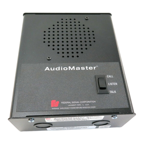
The Atkinson Dynamics “P” model is a panel mount intercom intended for 2-way
communications in industrial and vehicular applications. Each panel mount intercom
consists of a printed circuit board that is attached to a cover plate which has various
control functions. It is designed to be mounted in a customer-supplied panel. A
separate speaker/microphone that connects to the printed circuit board is utilized
for both receiving and transmitting audio signals. Nominal operating voltages for the
panel mount intercom include 12VDC, 24VDC, 120VAC, and 240VAC. The AC line is
fused with a 1/2 A 250 V type GMC fuse in the 120/240VAC intercoms. Basic model
specifications and additional model information is listed in Tables 1 and 2.
3
PRIMARY UNITS:
“C” Models default to Primary, or speaker mode. In Primary mode, the unit acts as a
speaker and broadcasts audio signals generated elsewhere in the intercom system.
Depressing the Talk switch turns the unit into a microphone and enables the user to
broadcast to all other intercoms in the system. Releasing the switch returns the unit to
Primary mode. Figures 2 through 4 illustrate Primary/Secondary intercom systems.
SECONDARY UNITS:
“D” Models default to Secondary, or microphone, mode. In Secondary mode, the unit
is designed to serve as a hands-free microphone with transmission to all Primary units
in the intercom system. The Secondary unit will act as a speaker and broadcast audio
transmissions only when the Talk switch of any Primary unit in the intercom system is
depressed. Figures 2 through 4 illustrate Primary/Secondary intercom systems.
Model AD-26P AD-56P AD-27P AD-57P
Supply Voltage 12 VDC 24 VDC 120 VAC,
50/60 Hz
240 VAC,
50/60 Hz
Audio Power Output (Max.) 8.0 watt 11.7 watt 11.3 watt 11.3 watt
Power Consumption (Max.) 20.0 watt 39.6 watt 28.8 watt 30.5 watt
Operating Current (Nominal) 1.47 A 1.65 A 0.240 A 0.127 A
Operating Temperature -31ºF to 150ºF
Shipping Weight 2 lb 1.5 oz 2 lb 1.5 oz 2 lb 11.6 oz 2 lb 11.6 oz
Dimensions See Figure 1
Ratings UL, cUL (Recognized Component Listing)
Table 1
Additional Model Information
Letter Group Function / Feature
“A” Call button
“C” Primary mode
“D” Secondary
Number Group
“-1” Remote power
“-8” Additional pre-amp for use with remote secondary speaker
Miscellaneous
“-M44” Remote speaker volume control
Table 2

4
CALL BUTTON:
“A” Models are equipped with a Call switch. Depressing the call switch transmits an
890 Hz tone to all units in the intercom system. The volume of the call signal is affected
by the volume control on the receiving unit, so if volume is turned all the way down at a
receiving station, the call signal will not be heard.
The call signal is louder than normal voice messages being carried on the line. Do
not depress the call switch while carrying on a conversation with someone on the
system. This will subject the listener to very loud sound levels.
PRE-AMPLIFIER:
“-8” Models are equipped with a pre-amplifier and are designed for use with
Secondary speaker units such as the AD-SV-25 Remote Speaker with Volume Control.
The “-M44” option equips the “-8” Primary unit with a knob for controlling the volume
of remote speakers. Figure 2 illustrates an intercom system with the “-8” and “-M44”
options.
EXTERNAL POWER SOURCE:
The use of an external power source allows the user to configure intercom systems
made up of “-1” DC powered Primary and Secondary units. Figure 4 illustrates such a
system.
SURGE PROTECTION:
Metal Oxide Varistor (MOV) devices are used to protect the audio lines. The intercom
must have Earth or Chassis Ground terminated to it to ensure surge protection.
The output amplifier of the Atkinson Dynamics intercom offers full short circuit
protection and overheat protection on the 120/240VAC intercoms only.
B. Unpacking.
After unpacking the Atkinson Dynamics panel mount intercom, examine it for damage
that may have occurred in transit. If the equipment has been damaged, do not attempt
to install or operate it, and file a claim immediately with the carrier stating the extent of
the damage. Carefully check all envelopes, shipping labels and tags before removing
or destroying them.
Before attempting to install the intercom, be sure that all parts listed in the KIT
CONTENTS LIST have been supplied.
C. Kit Contents List.
Qty. Description Part NumberQty. Description Part Number
1 Resistor, 1K, 1W 101216
1 Instruction Manual 2561542

5
D. Mounting.
The selection of the mounting location for the device, its controls, and the routing of
the wiring are to be accomplished under the direction of the facilities and the safety
engineer.
The panel mount intercom is designed to be mounted behind a customer-supplied panel.
1. Cut an opening and drill the four (4) mounting holes in the customer-supplied panel.
Refer to Figures 1 and 6.
2. Carefully insert the panel mount intercom into the customer-supplied panel.
3. Secure the panel mount intercom by installing screws in the four (4) mounting holes.
The four mounting holes are 0.191" in diameter and will accept a #8 mounting screw.
Hardware for mounting the intercom to the surface is left up to the installer.
Refer to instruction sheet 2561543, if necessary, for mounting the speaker.
E. Electrical Connections.
Connect the power wires labeled “PWR +” and “PWR -” on the panel mount intercom
to a nearby power source. On 120/240VAC models, the green/yellow wire labeled
“EGND” should be connected to earth ground. Connect the audio wires labeled “SPK”
(white/brown) and “COM” (white) from the intercom to the local speaker/microphone.
Models with the “-M44” option have an extra pair of audio wires labeled “REM SPK”
(black) and “COM” (white) that should be connected to a remote speaker. Connect
the audio wires labeled “AUD” (black or green) and “COM” (white) on the panel mount
intercom to the same color audio wires on another intercom in the system. Audio
wires should be sized properly by a licensed installation electrician for your specified
application. “C” and “D” models have a control line labeled “CTRL” (black). The
control line on a “C” model (Primary mode) connects to the control line on a “D” model
(Secondary mode). Refer to Figures 2 through 5 for typical connections and additional
wiring information.
Optional: A 1K, 1W resistor is included in a kit with each intercom. Installing the
resistor across the audio lines helps to reduce noise in certain environments. Only one
resistor needs to be installed on the lines for any system installation.
F. Service.
Federal Signal will service your equipment or provide technical assistance with any
problems that cannot be handled locally.
Any units returned to Federal Signal for service, inspection, or repair must be
accompanied by a Return Material Authorization. This R.M.A. can be obtained only
from the factory by calling (708) 534-4756. At this time a brief explanation of the
service requested or the nature of the malfunction, should be given.
Address all communications and shipments to:
Federal Signal
Service Department
2645 Federal Signal Drive
University Park, IL 60484-3167

6
2. Replacement Parts.
Replace fuse with GMC-1/2 only. DO NOT substitute.
Description Part Number
Kit, PC Board, 12V, AD-26C K2001878B-01
Kit, PC Board, 12V, AD-26D K2001878-02
Kit, PC Board, 24V, AD-56 K2001878-07
Kit, PC Board, 24V, AD-56C K2001878-08
Kit, PC Board, 12V, AD-26-8-M44 K2001896B
Kit, potentiometer with on/off switch K8590236A
Kit, toggle switch, 3PDT K8590239B
Kit, push button switch, DPDT (12/24V Models) K8590242A
Kit, push button switch, SPST (120/240V Models) K8590241A
Knob, volume control K141A129A
Rubber boot, toggle switch K288696A
Rubber boot, push button switch K288697A
Rubber boot, volume control K288A542A
Resistor, 1K, 1W K101216A

7
1
6.50"
5.90"
3.36"
4.67"
3.75"
4.38"
290A3828-01

8
2
Power Connections:
"PWR+" (Black) +DC-Power
12/24V Models "PWR-" (White) Common
12/24V Models
POWER PRIMARY
12-18VDC AD-26-8-M44P
22-30VDC AD-56-8-M44P
NOTES:
1. Mounting Holes
2. Talk/Listen Switch
3. Primary Off/On/Speaker Volume Control
4 Remote Secondary Speaker Volume Control
5. Cover Plate
6. On some installations, use shielded cable if
electrical noise is picked up.
OPERATING PRINCIPLE:
• Remote Secondary station is both a
speaker and a microphone.
• Primary is normally in "Listen" mode
until the talk button is pressed to talk to
Remote Secondary.
• Outgoing and incoming volumes are
controlled by separate controls on
Primary.
290A3828-02
"SPK" SPEAKER
(WHT/BRN)
LOCAL SPEAKER/MICROPHONE
MODEL AD-SF-25
PRIMARY
PANEL MOUNTED
INTERCOM
"COM"
COMMON
(WHT)
2
5
6
BLK WHT
BLK WHT
"REM SPK"
REMOTE
SPEAKER
(BLK)
"COM"
COMMON
(WHT)
200 FT. MAX.
AD-SF-25/AD-SS-25
"PWR +"(BLK)
*
SEE POWER
CONNECTIONS
*
"PWR -" (WHT)
1
1K
1WATT
3
4
REMOTE SECONDARY SPEAKER

9
3
290A3828-03
"SPK" SPEAKER
(WHT/BRN)
"SPK" SPEAKER
(WHT/BRN)
"COM"
COMMON
(WHT)
"COM"
COMMON
(WHT)
"PWR +"(BLK)
*
SEE POWER
CONNECTIONS
*
"EGND" (GRN/YEL)
"PWR -"(WHT)
"PWR +"(BLK)
*
"EGND" (GRN/YEL)
"PWR -"(WHT)
3 3
4
2
1
GRN
BLK
WHT
GRN
BLK
WHT
"AUD" AUDIO
"COM" COMMON
"CTRL" CONTROL
LOCAL SPEAKER/MICROPHONE
MODEL AD-SF-25
LOCAL SPEAKER/MICROPHONE
MODEL AD-SF-25
PRIMARY
PANEL MOUNTED
INTERCOM
SECONDARY
PANEL MOUNTED
INTERCOM
1K
1WATT
NOTES:
1. Mounting Holes
2. Cover Plate
3. Off/On/Speaker Volume Control
4. Press-to-Talk Switch
POWER CONNECTIONS:
"PWR+" (Black) +DC-Power 12/24V Models
HOT 120/240V Models
"PWR-" (White) Common 12/24V Models
Neutral 120/240V Models
"EGND" Earth Ground 120/240V Models only
(Green/yellow)
POWER PRIMARY SECONDARY
12-18VDC AD-26CP AD-26DP
120V 50/60Hz AD-27CP AD-27DP
22-30VDC AD-56CP AD-56DP
240V 50/60Hz AD-57CP AD-57DP
OPERATING PRINCIPLE:
• Primary normally listens to Secondary.
• Secondary talks to Primary hands-free,
without having to press a talk switch.
• To talk into Primary, press talk switch and
speak into speaker/microphone. Release
talk switch to listen.

10
4
290A3828-04
"SPK"
SPEAKER
(WHT/BRN)
LOCAL SPEAKER/MICROPHONE
MODEL AD-SF-25
"COM"
COMMON
(WHT)
34
2
1
5
(GRN)
(BLK)
(WHT)
(RED)
(GRN)
(BLK)
(WHT)
(RED)
"AUD" AUDIO
"PWR
+
"
+
DC
POWER
"COM" COMMON
"CTRL" CONTROL
SECONDARY
PRIMARY
PANEL MOUNTED
INTERCOM
3
1K
1WATT
NOTES:
1. Mounting Holes
2. Cover Plate
3. Off/On/Speaker Volume Control
4. Press-to-Talk Switch
5. Use shielded audio cable in
electrically noisy areas. Ground one end
of the shield to "earth" ground.
POWER CONNECTIONS:
"PWR+" (Black) +DC-Power 12/24V Models
"PWR-" (White) Common 12/24V Models
POWER PRIMARY SECONDARY
12-18VDC AD-26CP-1 AD-26D-1
OPERATING PRINCIPLE:
• PrimarynormallylistenstoSecondary.
• SecondarytalkstoPrimary"hands-free",
withouthavingtopressatalkswitch.
• TotalkintoPrimary,presstalkswitchand
speakintospeaker/microphone.Release
talkswitchtolisten.

11
290A3828-06
"SPK" SPEAKER
(WHT/BRN)
"SPK" SPEAKER
(WHT/BRN)
"COM"
COMMON
(WHT)
"COM"
COMMON
(WHT)
"PWR
+
"
(BLK)
*
SEE POWER
CONNECTIONS
*
"EGND" (GRN/YEL)
"PWR
-
"(WHT)
"PWR
+
"
(BLK)
*
"EGND" (GRN/YEL)
"PWR
-
"(WHT)
3 3
4 4
2
1
BLK
WHT
BLK
WHT
"AUD" AUDIO
"COM" COMMON
LOCAL SPEAKER/MICROPHONE
MODEL AD-SF-25
LOCAL SPEAKER/MICROPHONE
MODEL AD-SF-25
REMOTE A
PANEL MOUNTED
INTERCOM
REMOTE B
PANEL MOUNTED
INTERCOM
1K
1WATT
5
5
NOTES:
1. Mounting Holes
2. Cover Plate
3. Off/On/Speaker Volume Control
4. Talk/Listen Switch
5. Use shielded audio cable in electrically noisy
areas. Ground one end of the shield to
"earth" ground.
POWER CONNECTIONS:
"PWR+" (Black) +DC-Power 12/24V Models
HOT 120/240V Models
"PWR-" (White) Common 12/24V Models
Neutral 120/240V Models
"EGND" Earth Ground 120/240V Models only
(Green/yellow)
POWER PRIMARY SECONDARY
12-18VDC AD-26P AD-26P
120V 50/60Hz AD-27P AD-27P
22-30VDC AD-56P AD-56P
240V 50/60Hz AD-57P AD-57P
Operating Principle:
• Whenonetalks,allintercomswillhear.
• Totalktootherstations,pressthetalk/listen
switchandspeakintothespeaker/microphone.
• Releasetalk/listenswitchtolisten.

12
PANEL MOUNT TEMPLATE
6
5.60"
5.90"
4 x ø0.191"
3.75"
290A3828-07
3.60"
This manual suits for next models
3
Table of contents
Other Federal Signal Corporation Intercom System manuals

Federal Signal Corporation
Federal Signal Corporation Echo E2 Quick guide

Federal Signal Corporation
Federal Signal Corporation ez1 echo User manual

Federal Signal Corporation
Federal Signal Corporation E1 Operating instructions

Federal Signal Corporation
Federal Signal Corporation SELECTFONE SF-1245X-024 User manual

Federal Signal Corporation
Federal Signal Corporation 310LD-MV Quick guide

Federal Signal Corporation
Federal Signal Corporation E1 User manual

Federal Signal Corporation
Federal Signal Corporation SELECTFONE SF-1011P User manual

Federal Signal Corporation
Federal Signal Corporation C Series User manual