Federal Signal Corporation EOWS-612 User manual

FEDERAL SIGNAL CORPORATION
Model EOWS-612
Rotating Speaker Array
INSTALLATION INSTRUCTIONS

Limited Warranty
The Signal Division, Federal Signal Corporation, warrants each new product to be free from defects in
material and workmanship, under normal use and service, for a period of two years (one year for
Informer, EAS, and Federal software products) on parts replacement and one year on labor from the date
of delivery to the first user-purchaser. Federal Warning Systems warrants every 2001 Siren (Top of pole
only) to be free from defects in material, per our standard warranty, under normal use and service for a
period of Five years on parts replacement.
During this warranty period, the obligation of Federal is limited to repairing or replacing, as Federal
may elect, any part or parts of such product which after examination by Federal discloses to be defective
in material and/or workmanship.
Federal will provide warranty for any unit which is delivered, transported prepaid, to the Federal factory
or designated authorized warranty service center for examination and such examination reveals a defect
in material and/or workmanship.
This warranty does not cover travel expenses, the cost of specialized equipment for gaining access to the
product, or labor changes for removal and re-installation of the product. The Federal Signal Corporation
warranty shall not apply to components or accessories that have a separate warranty by the original
manufacturer, such as, but not limited to, batteries.
This warranty does not extend to any unit which has been subjected to abuse, misuse, improper
installation or which has been inadequately maintained, nor to units which have problems related to
service or modification at any facility other than Federal factory or authorized warranty service centers.
THERE ARE NO OTHER WARRANTIES, EXPRESSED OR IMPLIED, INCLUDING BUT NOT
LIMITED TO, ANY IMPLIED WARRANTIES OF MERCHANTABILITY OR FITNESS FOR A
PARTICULAR PURPOSE. IN NO EVENT SHALL FEDERAL BE LIABLE FOR ANY LOSS OF
PROFITS OR ANY INDIRECT OR CONSEQUENTIAL DAMAGES ARISING OUT OF ANY SUCH
DEFECT IN MATERIAL WORKMANSHIP.
2645 Federal Signal Drive, University Park, IL 60466
Phone: (800) 524-3021 Fax: (708) 534-4865
Website: http://www.federalwarningsystems.com

i
SAFETY NOTICES
People’s lives depend on your selection of suitable equipment and installation sites
and your safe installation, service, and operation of our products. Federal Signal recommends
the following publications from the Federal Emergency Management Agency for assistance
with planning an outdoor warning system: 1. The “Outdoor Warning Guide (CPG 1-17), 2.
“Civil Preparedness, Principles of Warning” (CPG 1-14), 3. FEMA-REP-1, Appendix 3
(Nuclear Plant Guideline), and 4. FEMA-REP-10 (Nuclear Plant Guideline). Contact Federal
Warning System’s Customer Care Center at: http://www.federalwarningsystems.com or 1-800-
524-3021 for further information about these publications.
It is important to read, understand and follow all instructions shipped with this product. In
addition, listed below are some other important safety instructions and precautions you should
follow.
PLANNING
•If suitable warning equipment is not selected, the installation site for the siren is not
selected properly or the siren is not installed properly, it may not produce the intended
optimum audible warning. Follow Federal Emergency Management Agency (FEMA)
recommendations.
•If sirens are not activated in a timely manner when an emergency condition exists, they
cannot provide the intended audible warning. It is imperative that knowledgeable people,
who are provided with the necessary information, are available at all times to authorize the
activation of the sirens.
•When sirens are used out of doors, people indoors may not be able to hear the warning
signals. Separate warning devices or procedures may be needed to effectively warn
people indoors.
•The sound output of sirens is capable of causing permanent hearing damage. To prevent
excessive exposure, carefully plan siren placement, post warnings, and restrict access to
areas near sirens.
•Activating the sirens may not result in people taking the desired actions if those to be
warned are not properly trained about the meaning of siren sounds. Siren users should
follow FEMA recommendations and instruct those to be warned of correct actions to be
taken.
•A siren that doesn’t work won’t provide any warning. After installation, service, or
maintenance, test the siren system to confirm that it is operating properly. Test the system
regularly to confirm that it will be operational in an emergency.
•If future service and operating personnel do not have these instructions to refer to, the
siren system may not provide the intended audible warning and service personnel may be
exposed to death, permanent hearing loss, or other bodily injury. File these instructions in
a safe place and refer to them periodically. Give a copy of these instructions to new
recruits and trainees. Also give a copy to anyone who is going to service or repair the
siren.

ii
SAFETY NOTICES
People’s lives depend on your safe installation, service and operation of our products. It is
important to read, understand and follow all instructions shipped with this product. In
addition, listed below are some other important safety instructions and precautions you should
follow:
INSTALLATION & SERVICE
•Electrocution or severe personal injury can occur when performing various installation
and service functions such as making electrical connections, drilling holes, or lifting
equipment. Therefore experienced electricians in accordance with national, state and any
other electrical codes having jurisdiction should perform installation. All work should be
performed under the direction of the installation or service crew safety foreman.
•The sound output of sirens is capable of causing permanent hearing damage. To prevent
excessive exposure, carefully plan siren placement, post warnings and restrict access to
areas near the sirens. Sirens may be operated from remote control points. Whenever
possible, disconnect all siren power including batteries before working near the siren.
•After installation or service, test the siren system to confirm that it is operating properly.
Test the system regularly to confirm that it will be operational in an emergency.
•If future service personnel do not have these warnings and all other instructions shipped
with the equipment to refer to, the siren system may not provide the intended audible
warning and service personnel may be exposed to death, permanent hearing loss, or other
bodily injury. File these instructions in a safe place and refer to them periodically. Give a
copy of these instructions to new recruits and trainees. Also, give a copy to anyone who is
going to service or repair the sirens. For additional copies, call the Federal Warning
Systems Customer Care Center at 800-524-3021 or write to them at 2645 Federal Signal
Drive, University Park, IL 60466.
OPERATION
•Failure to understand the capabilities and limitations of your siren system could result in
permanent hearing loss, other serious injuries or death to persons too close to the sirens
when you activate them or to those you need to warn. Carefully read and thoroughly
understand all safety notices in this manual and all operations-related-items in all
instruction manuals shipped with equipment. Thoroughly discuss all contingency plans
with those responsible for warning people in your community, company, or jurisdiction.

1
I. GENERAL DESCRIPTION.
Federal Model EOWS-612 Speaker Array (figure 1) is intended for use with
the Federal Model MCP Electronic Outdoor Warning Siren Control Unit. The Speaker
Array consists of six exponentially flared re-entrant speakers enclosed in a rectangular
sheet metal structure. Two eyebolts, located on top of the assembly, provide
convenient lifting points when it is necessary to hoist the Speaker Array.
It is not necessary for the installer to perform any electrical connections in the
interior of the Speaker Array. A 3-foot (0.914m) length of flexible conduit contains
wires which are interconnected between the Speaker Array and a junction box. In
addition, a 50-foot (15.2m) length of multi-conductor cable is connected to the
junction box for connection to the Control Unit.
This instruction sheet is intended to be used in conjunction with the MCP
Installation and Maintenance Instructions Manual (Federal Part No. 255305).
Figure 1. Model EOWS-612 Speaker Array
II. SPECIFICATIONS.
Number of Speakers…………………. 6
Speaker Type………………………… Exponentially flared, re-entrant
Dimensions (HWD)………………….. 81.5" x 51.6" x 32.8"
(207cm x 131cm x 83cm)
Weight (approx. – including…………. 370 pounds (168kg)
mounting hardware)

2
III. INSTALLATION.
IMPORTANT
Before proceeding, read and understand the
SAFETY NOTICES on pages iand ii of this
instruction sheet.
A. General.
During installation and before operation of all units,
steps 1, 2, and 3 must be performed.
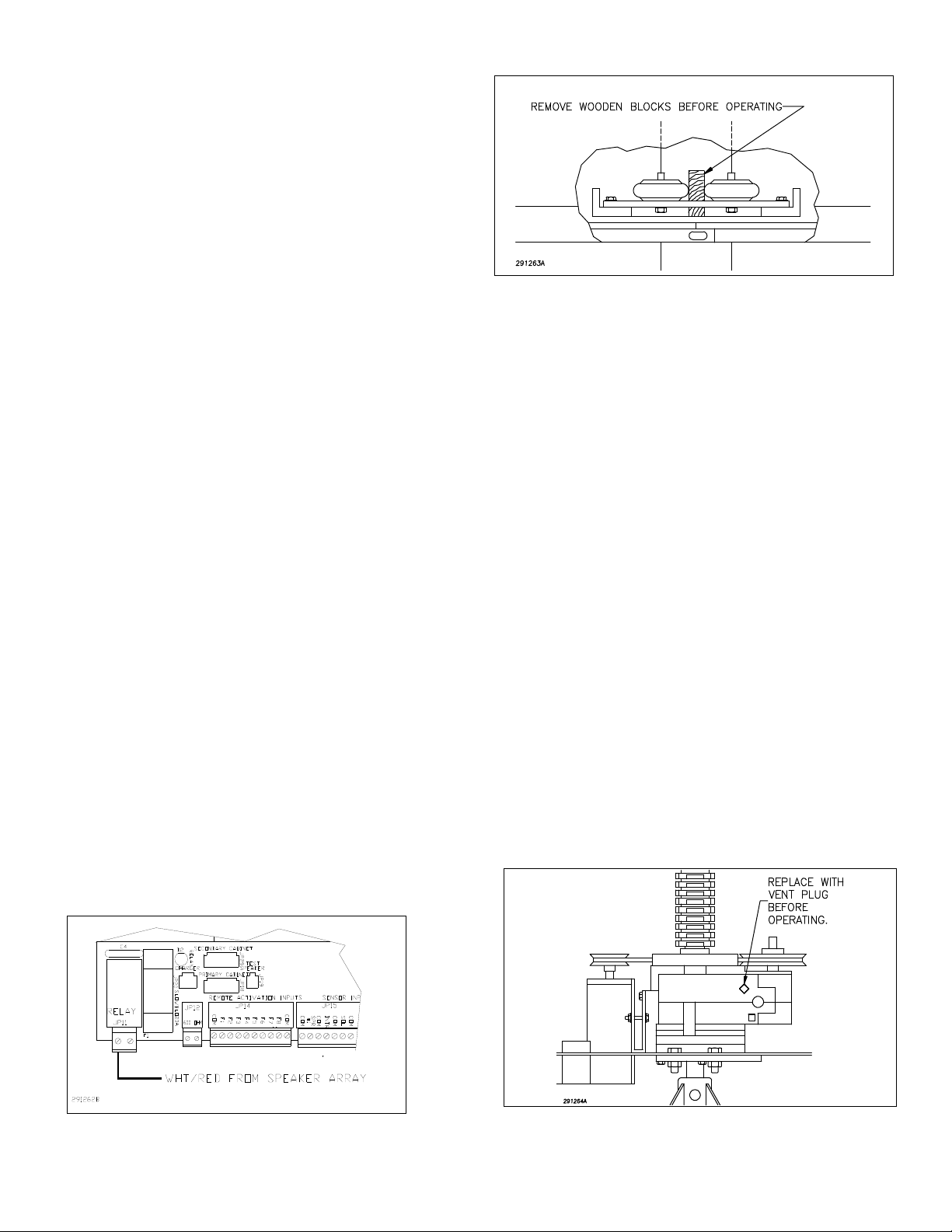
1. In order to control the rotation of the Speaker
Array, it is necessary to connect the wht/red wire from the
speaker array to JP25-1 on the motherboard (see figure 2).
CAUTION
To prevent damage to rotator assembly, steps
2 and 3 must be completed prior to operating
the unit.
2. Remove the bottom rear panel of the Speaker
Array. In some units, wooden blocks may be installed
between the roller brackets (see figure 3). If installed,
remove the wooden blocks from the roller brackets. The
rollers should be adjusted for minimal clearance to the pole
(approximately 1/32-inch).
3. Remove the second rear panel from the top of
the Speaker Array. Remove the pipe plug from the upper
tapped hole in the rotator gear box and replace with the
supplied vent plug (see figure 4).
4. Speaker Array Positioning.
The Home Switch Assembly is located on top
of the commutator rings. It allows the Speaker Array to be
positioned in one of four zones. The switch assembly is
factory set to align the Speaker Array with an arrow on the
Speaker Array base plate indicating Zone 1 (Home or
North).
If Home Switch Assembly adjustment is necessary,
it may be performed now or after Pole Mounting
Figure 2. Motherboard Relay Connection
Figure 3. Wooden Block Removal
or Flat Surface Mounting is completed. Refer to paragraph
III.D. for a description of the adjustment procedure.
5. Replace both panels.
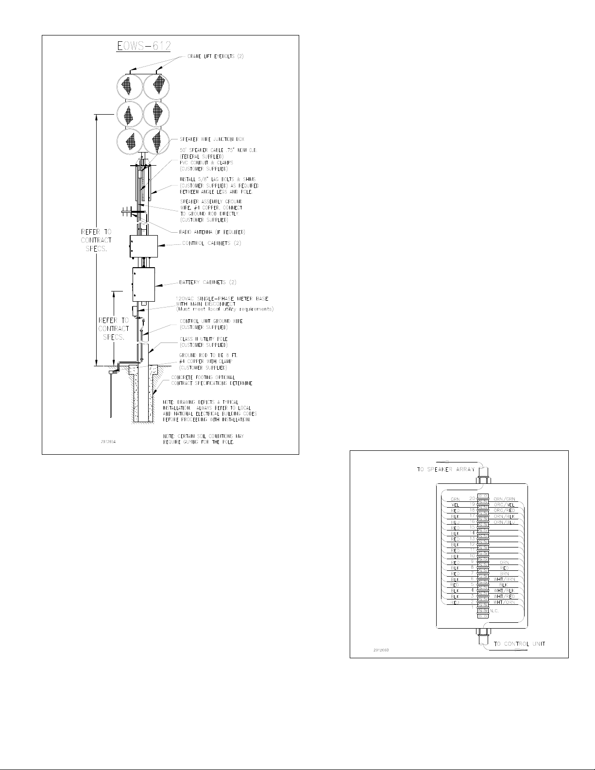
B. Pole Mount.
A typical pole mounted installation is shown in
figure 5. To provide optimum signalling effectiveness, the
siren must be mounted in accordance with FEMA standards.
Use a utility pole (ANSI Type 2 wooden pole or equivalent)
with a minimum horizontal ground stress rating of 3,700
pounds (1682kg).
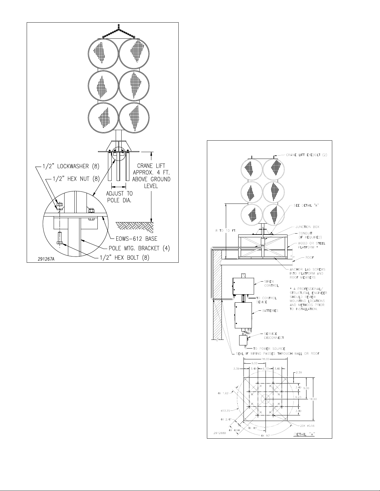
The siren is attached to the pole by means of a
stand provided by Federal. The stand consists of four legs
which must be connected to the base plate. The base plate
serves as a vertical support for the Speaker Array while
adding rigidity to the stand. To install the Speaker Array on
a Class 2 utility pole, proceed as follows:
1. Install the Class 2 utility pole in accordance
with accepted standards and practices.
2. Federal recommends that the 50-foot (15.2m.)
interconnecting cable be routed through user-supplied
conduit to the Control Unit. The bottom of the junction box
is equipped with a hole to accommodate a 1" weatherproof
conduit fitting.
Figure 4. Vent Plug Installation

3
Figure 5. Typical Pole Mounted Installation
It is most practical to install this fitting before
mounting the Speaker Array on the Class 2 utility pole. To
install a 1" conduit fitting in the junction box, proceed as
follows:
a. Remove the screws which secure the
junction box cover. Lift the cover.
b. Disconnect the 50-foot interconnecting
cable leads from the terminal strip inside the junction box.
As you disconnect a lead from the terminal strip, tag it so it
can be properly reinstalled. Figure 6 illustrates junction box
terminal strip connections for the Model EOWS-612.
c. Pull the interconnecting cable out through
the hole in the junction box. Install a user-supplied 1"
weatherproof electrical conduit fitting in the hole from
which the cable was removed. Do NOT install conduit in the
fitting at this time.
d. Route the interconnecting cable through the
conduit fitting and reconnect the leads removed from the
junction box terminal strip in step 2b. Use previously made
wire tags (step 2b) or see figure 6 to ensure the proper
connections.
3. Ensure that the wooden blocks, located near
the rollers at the bottom of the rotator assembly, have been
removed as described in paragraph III.A.2.
WARNING
The eyebolts and hoisting bracket do not have
sufficient strength to support the combined
weight of the Speaker Array and a utility pole.
Therefore, do NOT attempt to erect the pole
and Speaker Array together using the eyebolts
as lifting points.
Also, never attempt to lift the Speaker Array
by only one eyebolt. The assembly is designed
to be lifted by utilizing both eyebolts.
4. Connect the hook of a crane to the array
eyebolts. Ensure that both eyebolts are fastened to the end of
the crane. Lift the Speaker Array four or five feet off the
ground. Install the stand as shown in figure 7. Snug-up the
1/2 inch bolts (not tight).
5. Raise the Speaker Array to the necessary
height, and lower it over the pole so that the base plate rests
on the top of the pole.
6. If necessary, insert shims between the legs and
the pole to level the Speaker Array. Slots are provided in the
Figure 6. EOWS-612 Junction Box Terminal Strip

4
Figure 7. Stand Assembly
legs to accommodate different pole diameters. Move the legs
in or out until the proper “fit” is found. Tighten all eight 1/2-
inch bolts that secure the legs to the base plate. Bolt the siren
legs to the pole, using two 1/2-inch lag bolts (user-supplied),
at least four inches long, for each leg.
7. Install the Control Unit by performing the
procedure in the MCP Installation and Maintenance
Instructions Manual (Federal Part No. 255305).
NOTE
The 3-foot length of flexible conduit allows the
junction box to be positioned after the conduit
has been installed.
8. Route the multi-conductor cable from the
junction box, through conduit, to the Control Unit. Tighten
the conduit connectors on the junction box and Control Unit.
9. Secure the junction box to the pole with four
1/4-inch lag bolts (not supplied).
C. Flat Surface Mount.
WARNING
The sound output of the Model EOWS-612 is
capable of causing permanent hearing
damage. Therefore, it is recommended that
notices be posted at all roof access points
indicating a roof-mounted siren is installed.
This installation configuration is practical when the
installation site is on a flat-roofed building. The siren can be
anchored directly to the roof, on a platform as shown in
figure 8, or on a weight distribution mat like the one shown
in figure 9. This mat is required when the siren mounting
Figure 8. Typical Surface Mounted Installation

5
Figure 9. Weight Distribution Mat Construction
surface is unable to support the weight of the siren. This mat
distributes the Speaker Array weight to approximately 18
pounds per square foot (88kg per square meter). When
installing the siren on a flat roof, be sure that the Speaker
Array is mounted above any obstructions which may reduce
sound propagation.
To install the Speaker Array on a flat roof or other
flat surface, proceed as follows:
1. If desired, construct a platform for mounting
the Speaker Array. The platform must be capable of
supporting at least 350 pounds (162 kg.) and withstanding a
siren wind load of 110 mph (177kmph). Platform
construction details are left to the builder and the safety
engineer. Locate the platform at the siren installation site,
and anchor the platform to the mounting surface.
WARNING
The eyebolts and hoisting bracket do not have
sufficient strength to support the combined
weight of the Speaker Array and a platform.
Therefore, do NOT attempt to lift the Speaker
Array and platform together using the eyebolts
as lifting points.
Also, never attempt to lift the Speaker Array
by one eyebolt. The assembly is designed to
be lifted by utilizing both eyebolts.
2. Hoist the Speaker Array to the installation site
using both eyebolts as lifting points.
3. Anchor the Speaker Array to the mounting
surface with user-supplied 1/2" lag bolts or nuts and bolts, as
appropriate, through the four inner and four outer mounting
holes in the Speaker Array base plate.
NOTE
When using the weight distribution mat, use
the mounting holes shown in figure 9. When
mounting the siren directly on a roof, be sure
to install waterproof joints where the mounting
bolts pass through the roof so that water does
not enter the building.
4. Federal recommends that the 50-foot (15.2m.)
interconnecting cable be routed through user-supplied
conduit to the Control Unit. If this recommended installation
is to be performed, a user-supplied 1" conduit fitting must be
installed in the junction box as described in paragraph
III.B.2. of this Instruction Sheet.
5. Ensure that the wooden blocks, located near
the rollers at the bottom of the rotator assembly, have been
removed as described in paragraph III.A.2.
6. Install the Control Unit by performing the
procedure in the MCP Installation and Maintenance
Instructions.
NOTE
The 3-foot length of flexible conduit allows the
junction box to be positioned after the conduit
has been installed.

6
7. Route the multi-conductor cable from the
junction box, through conduit, to the Control Unit. Tighten
the conduit connectors on the junction box and Control Unit.
8. Secure the junction box with four user-supplied
1/4-inch lag bolts.
D. Home Switch Adjustment.
Point the Speaker Array in the direction designated
as Home. If using a compass, be aware of the magnets in the
Speaker Array. See figure 10. Adjust the switch as follows:
1. Remove the rear panel from the top of the
Speaker Array. Retain the screws.
2. Loosen the set screw on the top of the flexible
shaft.
3. Rotate the flexible shaft until a short is
detected between the orange/black and orange/yellow wires
in the 50-foot interconnecting cable.
4. Tighten the set screw on the flexible shaft.
5. Replace the rear panel and secure with the
previously removed screws.
Figure 10. Home Switch Adjustment
E. Signal Connections.
All interconnections between the Junction Box
and the Control Unit are accomplished by means of a 50-
foot length of multi-conductor cable. This cable is factory-
connected to the junction box. A slip-on terminal is factory-
installed on the free end of each color-coded conductor in
the cable.
NOTE
Trim excess interconnecting cable. Do not coil
the cable or leave more than 2 feet of cable in
the Control Unit’s cabinet.
See figure 11 in this sheet when making electrical
connections.
F. AC Power Connections.
Route 1" conduit between the user-supplied fused
disconnect switch and the 1" conduit fitting in the bottom of
the Control Unit enclosure. Connect the AC power as shown
in figure 11.
CAUTION
To prevent moisture from entering the cabinet,
it is important to fill conduit fittings (speaker
cable and AC power) with a silicon sealant.
G. Checkout.
Refer to the MCP Installation and Maintenance
Instructions Manual for testing.

7
Figure 11. EOWS-612 Wiring Diagram

256622
REV.F6/03 PrintedinU.S.A.
Table of contents
Other Federal Signal Corporation Speakers System manuals