feedback MS150 User manual

MS150ModularServoWorkshop-GettingStarted
33-008-1M5

MS150 Modular Servo Workshop
Getting Started
33-008-1M5
Feedback
Feedback Instruments Ltd, Park Road, Crowborough, E. Sussex, TN6 2QR, UK.
Telephone: +44 (0) 1892 653322, Fax: +44 (0) 1892 663719.
Manual: 33-008-1M5 Ed02 991116
Printed in England by Fl Ltd, Crowborough
Feedback Part No. 1160–330081M5

Notes

MS150 MODULAR SERVO
Getting Started Preface
33-008-1M5 i
THE HEALTH AND SAFETY AT WORK ACT 1974
We are required under the Health and Safety at Work Act 1974, to make available to users of this equipment certain information
regarding its safe use.
The equipment, when used in normal or prescribed applications within the parameters set for its mechanical and electrical performance,
should not cause any danger or hazard to health or safety if normal engineering practices are observed and they are used in
accordance with the instructions supplied.
If, in specific cases, circumstances exist in which a potential hazard may be brought about by careless or improper use, these will be
pointed out and the necessary precautions emphasised.
While we provide the fullest possible user information relating to the proper use of this equipment, if there is any doubt whatsoever
about any aspect, the user should contact the Product Safety Officer at Feedback Instruments Limited, Crowborough.
This equipment should not be used by inexperienced users unless they are under supervision.
We are required by European Directives to indicate on our equipment panels certain areas and warnings that require attention by the
user. These have been indicated in the specified way by yellow labels with black printing, the meaning of any labels that may be fixed to
the instrument are shown below:
CAUTION -
RISK OF
DANGER
CAUTION -
RISK OF
ELECTRIC SHOCK
CAUTION -
ELECTROSTATIC
SENSITIVE DEVICE
Refer to accompanying documents
PRODUCT IMPROVEMENTS
We maintain a policy of continuous product improvement by incorporating the latest developments and components into our equipment,
even up to the time of dispatch.
All major changes are incorporated into up-dated editions of our manuals and this manual was believed to be correct at the time of
printing. However, some product changes which do not affect the instructional capability of the equipment, may not be included until it is
necessary to incorporate other significant changes.
COMPONENT REPLACEMENT
Where components are of a ‘Safety Critical’ nature, i.e. all components involved with the supply or carrying of voltages at supply
potential or higher, these must be replaced with components of equal international safety approval in order to maintain full equipment
safety.
In order to maintain compliance with international directives, all replacement components should be identical to those originally
supplied.
Any component may be ordered direct from Feedback or its agents by quoting the following information:
1. Equipment type
3. Component reference 2. Component value
4. Equipment serial number
Components can often be replaced by alternatives available locally, however we cannot therefore guarantee continued performance
either to published specification or compliance with international standards.

MS150 MODULAR SERVO
Preface Getting Started
33-008-1M5ii
DECLARATION CONCERNING ELECTROMAGNETIC COMPATIBILITY
Should this equipment be used outside the classroom, laboratory study area or similar such place for which it is designed and sold then
Feedback Instruments Ltd hereby states that conformity with the protection requirements of the European Community Electromagnetic
Compatibility Directive (89/336/EEC) may be invalidated and could lead to prosecution.
This equipment, when operated in accordance with the supplied documentation, does not cause electromagnetic disturbance outside its
immediate electromagnetic environment.
COPYRIGHT NOTICE
©Feedback Instruments Limited
All rights reserved. No part of this publication may be reproduced, stored in a retrieval system, or transmitted, in any form or by any
means, electronic, mechanical, photocopying, recording or otherwise, without the prior permission of Feedback Instruments Limited.
ACKNOWLEDGEMENTS
Feedback Instruments Ltd acknowledge all trademarks.
IBM, IBM - PC are registered trademarks of International Business Machines.
MICROSOFT, WINDOWS 95, WINDOWS 3.1 are registered trademarks of Microsoft Corporation.
MATLAB is a registered trademark of Mathworks Inc.

MODULAR SERVO
Getting Started Contents
33-008-1M5 TOC 1
TABLE OF CONTENTS
1. INTRODUCTION AND DESCRIPTION 1-1
1.1. Equipment and requirements 1-1
1.1.1. Knowledge Level Required 1-2
1.1.2. Minimum Hardware and Software Requirements 1-2
1.2. Principal system interconnections and software operation 1-3
2. MODEL AND CONTROL ALGORITHMS 2-1
2.1. PID control 2-2
2.2. State feedback control 2-2
2.3. Time - optimal control 2-3
2.4. Adaptive control 2-3
3. STARTING , TESTING AND STOPPING PROCEDURES 3-1
3.1. Starting procedure 3-1
3.2. Testing and troubleshooting 3-2
3.3. Stopping procedure 3-5
4. MENU DESCRIPTION 4-1
4.1. Tools 4-1
4.2. Design and identification 4-9
4.3. Models and experiments 4-16
5. FIRST EXAMPLES 5-1
5.1. Example 1. Closed-loop control system with state feedback gains 5-1
5.2. Example 2. Ziegler-Nichols method for designing PID controller 5-2

MODULAR SERVO
Contents Getting Started
TOC 2 33-008-1M5
6. CONNECTING THE PC AND THE SERVO 6-1
6.1. PCL-812PG acquisition board: 6-2
6.2. Switch settings - 16 bit board 6-2
6.3. Jumper Settings 6-3
6.4. Switch SW1 settings for 8 bit full length PCL - 812 board 6-4
6.5. Installation of PCL-812 Board 6-4

CHAPTER 1
MODULAR SERVO
Getting Started Introduction and Description
33-008-1M5 1-1
1. INTRODUCTION AND DESCRIPTION
The Modular Servo Workshop (MSW)
is an open-architecture software environment for
real-time control experiments using the Feedback
digital servomechanism. The main
concept of the Modular Servo Workshop was to create a rapid and direct path from
control system design to hardware implementation. The Modular Servo Workshop
supports the real-time design and implementation of advanced control methods, using
MATLAB
and Simulink tools, and extends the MATLAB
environment in the solution of
digital servomechanism control problems.
The integrated software supports all phases of a control system development:
•on-line process identification,
•control system modelling, design and simulation,
•real-time implementation of control algorithms.
The Modular Servo Workshop is intended to provide a user with a variety of software tools
to facilitate:
•on-line information flow between the process and the MATLAB
environment,
•real-time control experiments using embedded algorithms,
•development, simulation and application of user-defined control algorithms
.
The Modular Servo Workshop
uses standard PC hardware platforms and Microsoft
Windows operating systems. Version 1.02 of the software works with MATLAB
5.1 & 5.2
and Simulink 2.1 and 2.2. It is not compatible with earlier versions of MATLAB software.
1.1. Equipment and Requirements
The Modular Servo Workshop is distributed in compressed format on a CD-ROM.
Installation procedure is a standard one applied for Feedback MATLAB compatible
products (see The Software Installation Guide – 33-000 for details). A full set of software
and manuals consists of:
•CD-ROM,
•Getting Started 33-008-1M5 ( this manual),
•Reference Guide 33-008-2M5
•External Interface 33-008-3M5
•Advanced Teaching Manual, 33-008-4M5
•Software Installation Guide. 33-000M5

CHAPTER 1 MODULAR SERVO
Introduction Getting Started
1-2 33-008-1M5
1.1.1. Knowledge Level Required
The manual assumes that the user has a basic experience with one of the Feedback
digital servomechanisms, with MATLAB 5 & Simulink from MathWorks Inc, and with the
Microsoft Windows 95 or NT operating System. More experience in control is required for
experiments described in the ADVANCED TEACHING manual. Some practise in C-
language programming is expected for application of the EXTERNAL INTERFACE.
1.1.2. Minimum Hardware and Software Requirements
Modular Servo system - Feedback part numbers
OA150A Operational Amplifier
AU150B Attenuator
PA150C Pre-Amplifier
SA150D Servo Amplifier
PS150E Power Supply
DCM150F DC Motor
IP150H Input Potentiometer
OP150K Output Potentiometer
LV150L Magnetic Brake Load
GT150X Gearbox/Tachometer
MS150Z Accessories plus Magnetic Baseplate
33-301 Interface unit
33-300 Digital Encoder
PC and boards
486DX or above PC with 16 Mbytes memory, and 200 Mbytes available disk space, 16x
CD Rom, SVGA screen,
PCL-812PG or RT-DAC data acquisition board
Software
The MS150 uses a standard PC hardware platform and the standard Microsoft Windows
95 or NT operating system, and
minimum
MATLAB 5.1, Simulink 2.1, Control and Signal
Processing Toolboxes.from the Mathswork Inc. Certain specialised controllers, developed
in future Teaching Manual releases, may require the use of
additional
MATLAB toolboxes.
An appropriate C compiler is required for use of the External Interface.
CD-ROM with Feedback Modular Servo software
CHAPTER 1
MODULAR SERVO
Getting Started Introduction and Description
33-008-1M5 1-3
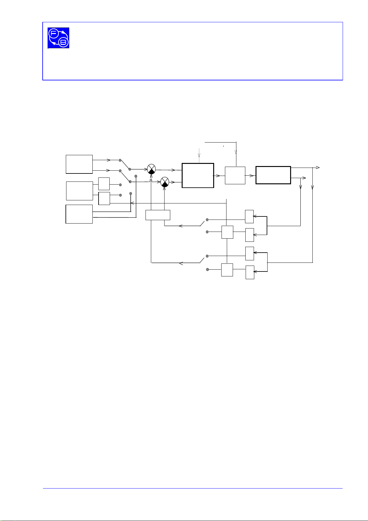
1.2. Principal system interconnections and software operation
The control system applied for the servomechanism is given in a block diagram form in
Figure 1-1.
D/A
basic clock
controller
A/D
A/D
A/D
S
S
S
S
A/D
1
2
1
2
y
1
y
2
y
1d
y
2d
internal
excitation
source
excitation
source
external
auxiliar
y
clock
filter
uDC motor
Simulink
generator
sampling T0
Figure 1-1: Block diagram of the control system
Two process outputs are considered: the position y1 and the speed y2. Process outputs
can be measured as continuous signals (sensors S2) digitised by analogue-to-digital
converters (A/D) or a direct digital measurement technique can be used (sensors S1 -
encoder). The reference input (desired value) can be generated in a digital form using an
internal excitation source or, alternatively, an external MS150H Input potentiometer can
be applied. Additionally, the Simulink Signal Generator can be applied as a source of
excitation signal when the Simulink model is used.
The hardware and software connections of the
Modular Servo Workshop
are given in
Figure 1-2.
The software of the MSW
consist of the following main parts:
•
Real-time Kernel (RTK),
•
Modular Servo Toolbox.

CHAPTER 1 MODULAR SERVO
Introduction Getting Started
1-4 33-008-1M5
The Real-time Kernel is collection of real-time tasks supervised by a task manager.
Control algorithms, filtering procedures and outputs from the software generator of the
excitation signal, are activated by the timer interrupt. Notice, that, inside the real-time
kernel, the basic feedback loop of the control system is closed.
External
excitation
position
position
speed
PC - com
p
uter +MS-WINDOWS
RTK Data acquisition & control
y
1d
y
2d
filter
PCL-812PG or RT-DAC
buffer
p
rocess data
controller
selection&
parameters
M
ATLAB+SIMULINK
Internal
excitation Educational Servo Toolbox
to DC motor
- software
- hardware - software controlled
Modular Servo 150
from
Encoder
from
tachogenerator
embedded
controllers
commu-
nication
interface
(
*
)
(*)
(*)
(*) - user defined by External Interface software
3
3-301 Analogue Control Interface
DC Motor
Digital encoder Potentiometer
Gearbox/Tacho
brake
Figure 1-2: Closed-loop control system of the Modular Servo
The
Modular Servo Toolbox
, using MATLAB matrix functions, provides the functions
specialised for real-time control of the Feedback digital servomechanism. It is the general
assumption that the toolbox is an open system. This approach by its nature forces the
basic functions of the toolbox to be in the user domain. It enables the user to maintain his
own system, and to customise control algorithms to satisfy the requirements better.
In addition, however, in the
Main Control Window
typical "paths" through the toolbox are
provided, and typical control problems are introduced.

CHAPTER 1
MODULAR SERVO
Getting Started Introduction and Description
33-008-1M5 1-5
The collection of the toolbox functions can divided into two main categories:
•Real-Time Kernel communication functions,
•Real-Time Kernel configuration functions.
The toolbox functions and MATLAB functions can be used at different application levels.
In this manual the following convention is used:
•application level 1 - RTK communication and configuration functions, MATLAB
functions,
•application level 2 - menu-driven experiments and simulations,
•application level 3 - external interface software for advanced users to create his
own algorithms.
Application level 1 means a direct use of the toolbox functions controlling the information
flow between process sensors, RTK and MATLAB environment. The functions used at
this level configure a real time kernel, embedded controllers and excitation sources (see
Reference Manual – 33-008-2M5 for details).
At application level 2 the function
es
initialises the menu-driven part of the toolbox .
At application level 3 the EXTERNAL INTERFACE software allows the creation of user-
defined algorithms and the modification of communication functions (see the External
Interface Manual 33-008-3M5 for details).

CHAPTER 1 MODULAR SERVO
Introduction Getting Started
1-6 33-008-1M5
Notes

CHAPTER 2
MODULAR SERVO
Getting Started Model And Control Algorithms
33-008-1M5 2-1
2. MODEL AND CONTROL ALGORITHMS
In this section a brief review of the embedded control algorithms is given. For a detailed
description of control algorithms refer to the Advanced Teaching Manual ( 33-008-4M5 ).
The design process for the controllers listed below was performed assuming a linear
model of the DC motor in the form of two first-order linear differential equations. This
representation is generally known as a state-space model:
0
x=0)=t(x
DuCx=y
Bu+Ax=
dt
dx
+
For the DC motor we obtain:
0=D,
10
01
=C,
T
K
0
=B,
1
0
10
=A
s
s
−s
T
where: x is the vector with components x1(position of the DC motor shaft or angle) and
x2(the speed) and u is the control input.
The general solution of the state-space equations is:
Du(t)+)dBu(e+0x
At
eC=y(t) t
0
)-A(t
∫
ττ
τ
The discrete model of DC motor can be obtained by transformation of the continuous
system
dx/dt = Ax + Bu assuming a zero-order hold and sample time T0:
x[n+1]=Adx[n] + Bdu[n]
y[n] = Cdx[n]
The system can be classified as a multivariable (SIMO) because it has two measurable
states and one control variable.

CHAPTER 2 MODULAR SERVO
Model And Control Algorithms Getting Started
2-2 33-008-1M5
The following control algorithms are used for the first control experiments:
•PID
•state feedback controllers : LQ and deadbeat
•time-optimal
•adaptive controller
The user can develop and apply his own algorithm using the tools described in the
External Interface Manual - 33-008-3M5.
2.1. PID control
The PID controller has the form:
[]
uK kK kK k k
pi
k
n
d
=+ +−−
=
∑
(() () () ( ))
εεεε
11
011
1
where:
ε1is position error, Kpis gain coefficient, Kiis integration gain, and Kdis derivative
gain.
The constants Kp, Ki and Kd can be chosen according to the Ziegler-Nichols rule or
another controller designing procedure.
2.2. State feedback control
The state feedback controller has the form:
u = - (K1ε1+K2ε2)
where:ε1- is position error,
ε2- is speed error,
K1,K2are controller gains.
The LQ optimal feedback gain vector K = [K1,K2] can be calculated in such a way that the
feedback law u = -Kε; where ε= [ε1,ε2] minimises the cost function:
∫
∞
=0
Tdt)u+( RuQxxJ T, where Q and R are the weighting matrices,
subject to the state equation: dx/dt = Ax + Bu

CHAPTER 2
MODULAR SERVO
Getting Started Model And Control Algorithms
33-008-1M5 2-3
Another selection of state-feedback gains is based on 'dead-beat' principle. The feedback
gain vector K = [K1,K2] is calculated in such a way that eigenvalues of the state matrix of
the discrete closed-loop system are equal to zero:
eig(Ad - Bd * K) = 0
The controller has the property that he drives the states of the closed-loop system from an
arbitrary initial state to zero value in at most N-steps (N = dim(Ad)).
2.3. Time - optimal control
In this case typical for linear systems „bang-bang” control principle is used. A full
description and principles of operation of the time-optimal controller are given in the
Advanced Teaching Manual – 33-008-4M5.
2.4. Adaptive control
The adaptive controller is based on the reference model idea. A full description of the
controller is given in the Advanced Teaching Manual - 33-008-4M5.

CHAPTER 2 MODULAR SERVO
Model And Control Algorithms Getting Started
2-4 33-008-1M5
Notes

CHAPTER 3
MODULAR SERVO
Getting Started Starting, Testing and Stopping Procedures
33-008-1M5 3-1
3. STARTING , TESTING AND STOPPING PROCEDURES
3.1. Starting procedure
Perform all connections as described in Section 6 of this manual. They will ensure correct
communications between Computer – Advantech PCL812PG i/o board – 33-301
Analogue Interface unit and the rest of modular servo MS150 units.
Ensure that the Attenuator Unit AU150B has the top gain-pot set to a value around 8 and
the Pre-Amplifier Unit PA 150C has the pot to ‘zero set’. The connections to these units to
be made as shown in Section 6. There should be approximately ‘no motion’ noticed on
the motor unit.
If the motor is turning, then the output produced by the computer (i/o board) is set to high.
Follow the Calibration 33-301 routine in order to adjust offsets and gains for all 4
channels.
Note: Values stated in these manuals would not provide good performance on other
systems. The numbers should be around the ones shown in manual.
In the MS-WINDOWS environment invoke MATLAB by double clicking on the MATLAB
icon. The
Matlab Command Window
opens. Then type:
es
and then the
Main Control Window
of MSW opens (see Figure 3-1)
Figure 3-1: The Main Control Window
Then go through the following steps:

CHAPTER 3 MODULAR SERVO
Starting, Testing and Stopping Procedures Getting Started
3-2 33-008-1M5
•double click on the
Set base address
button. This set the base address of the i/o card.
•If the address of your data acquisition board agrees with the default value then accept
it, otherwise type the proper address. System may terminate if entered the incorrect
number.
Note: You can set the base address equal to zero. Then you can work with
the control software without a connection to the external hardware. In this
case the measurement data are produced by a built-in model of the DC
motor, which allows off-line testing of new control software.
Calibrate the 33-301 Analogue Control Interface Unit following step-by-step instruction
brought up by each individual window.
3.2. Testing and troubleshooting
Now you are ready to start an experiment. This will give an indication if the output
measurements are correct. First go through the following steps to check the proper
operation of your hardware:
•double click the
Basic test
button. The following window (Figure 3-2) appears:

CHAPTER 3
MODULAR SERVO
Getting Started Starting, Testing and Stopping Procedures
33-008-1M5 3-3
Figure 3-2:
Basic test
window
•set the position of the OP150K manually to 70 degrees anticlockwise. If this is not set
to 70 degrees, the Basic Test program will not provide results similar to the ones shown
in Fig. 3.3. This is because when applying a square wave (sudden reverse in the input
signal) the pot on the OP150K will rotate more than 180 degrees.
•click the
Start
button and wait for results.
This test performs the action in three steps:
1. sets the source of data as follows:
•Channel 1 - angle measured from A/D converter [deg] (using A/D1 channel of the
Analogue Control Interface),
•Channel 2 - angle measured from digital encoder [deg],
•Channel 3 - velocity measured from A/D converter [deg/s] (using A/D2 channel of
the Analogue Control Interface),
•Channel 4 - velocity calculated from encoder measurements [deg/s].
2. sends a step input to system, collects the data,
3. plots the results.
Typical results of the basic test are shown in Figure 3-3.
On the screen you will see the following colours: red-channel 1, blue-channel 2, green-
channel 3 and black-channel 4. In this case all components of the system are working
correctly.
Other manuals for MS150
1
Table of contents
Other feedback Laboratory Equipment manuals

Popular Laboratory Equipment manuals by other brands

Buchi
Buchi Scrubber K-415 Operation manual

Nahita
Nahita 503 Series quick start guide

Sartorius
Sartorius Vivacon 500 operating instructions

Boekel
Boekel Slide Moat 240000 operating instructions

DENTAURUM
DENTAURUM Compact Megaplus Instructions for use

Simpnic
Simpnic SiMP UV-C Sterilizer Box Quick installation guide


Renfert
Renfert BASIC eco quick start guide

Kendro
Kendro HERAcell 150 operating instructions

Thermo Scientific
Thermo Scientific DensityPRO-T installation guide

ProteinSimple
ProteinSimple Jess user guide

Selecta
Selecta PRECISTERM 2L instruction manual

Agilent Technologies
Agilent Technologies 6890N Troubleshooting