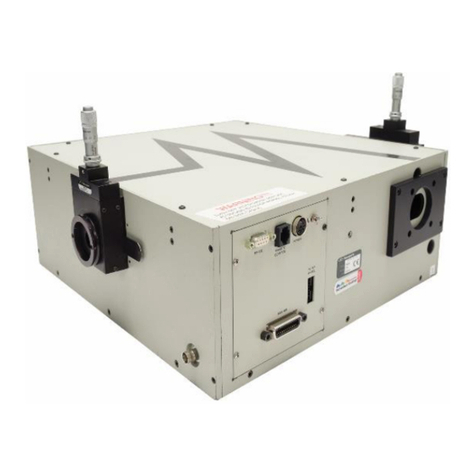
Newport Oriel LCS-100 User manual

1M-66450
APEX Illuminators
M94011A Rev: April 2018
Famil
y
of Brands – Corion®• New Focus™ • Oriel®Instruments • Richardson Gratin
g
s™ • S
p
ectra-
94011A
94011A-ES
User's Manual
Oriel
®
LCS-100
TM
Small Area Sol1A

M94011A
Oriel®LCS-100TM Small Area Sol1A
- 2 -
TABLE OF CONTENTS
1INTRODUCTION .................................................................................................................................... 4
2SAFETY.................................................................................................................................................. 6
2.1UV AND VISIBLE RADIATION ..................................................................................................... 6
2.2LAMP EXPLOSION ...................................................................................................................... 6
2.3OZONE ......................................................................................................................................... 7
2.4ELECTRICAL SHOCK .................................................................................................................. 7
2.5EMI................................................................................................................................................ 8
2.6HEAT ............................................................................................................................................ 8
2.7GENERAL WARNINGS ................................................................................................................ 8
2.8GENERAL CAUTIONS ................................................................................................................. 9
2.9WARNING SYMBOLS .................................................................................................................. 9
3UNPACKING AND ASSEMBLING THE SYSTEM ............................................................................... 12
3.1MODEL 75 HEAVY DUTY MOUNTING ROD............................................................................. 12
3.2POST CLAMP AND ANGLE BRACKET..................................................................................... 13
3.3ANGLE BRACKET MOUNTING TO BOTTOM OF LCS-100TM ................................................... 13
3.4ROD ASSEMBLY........................................................................................................................ 14
4FILTER INSTALLATION / REPLACEMENT......................................................................................... 15
5LAMP INSTALLATION / REPLACEMENT ........................................................................................... 17
5.1ARC LAMPS ............................................................................................................................... 17
6OPERATION......................................................................................................................................... 21
6.1FUSE CHANGE FOR 220VAC ................................................................................................... 21
6.2MOUNTING OPTIONS ............................................................................................................... 22
6.3LAMP START ............................................................................................................................. 23
6.4SHUTTER ................................................................................................................................... 24
6.5IRRADIANCE ADJUSTMENT..................................................................................................... 25
7TROUBLESHOOTING.......................................................................................................................... 26
8SPECIFICATIONS................................................................................................................................ 27
9WARRANTY & SERVICE ..................................................................................................................... 30
CONTACTING ORIEL® INSTRUMENTS ........................................................................................ 30
REQUEST FOR ASSISTANCE / SERVICE...................................................................................... 30
REPAIR SERVICE ............................................................................................................................ 31
NON-WARRANTY REPAIR .............................................................................................................. 31
WARRANTY REPAIR........................................................................................................................ 31
LOANER / DEMO MATERIAL........................................................................................................... 32

M94011A
Oriel®LCS-100TM Small Area Sol1A
- 3 -
LIST OF TABLES
SPECIFICATIONS of LCS-100 TM Solar Simulator ..................................................................................... 27
Typical Output Power from LCS-100 TM Solar Simulator ............................................................................. 27
LIST OF FIGURES
Figure 1: LCS-100TM Model 94011A shown with optional SA-12 Mount Plate............................................... 5
Figure 2: LCS-100TM Model 94011A-ES shown with optional SA-12 Mount Plate ........................................ 5
Figure 3: Model 75 Rod Mounting .............................................................................................................. 12
Figure 4: 90 Degree angle bracket to Post Clamp assembly ..................................................................... 13
Figure 5: 90 Degree angle bracket assembly to bottom of unit.................................................................. 13
Figure 6: Rod assembly ............................................................................................................................. 14
Figure 7: Filter retention thumbscrews ....................................................................................................... 15
Figure 8: Filter assembly insertion and removal......................................................................................... 16
Figure 9: Filter assembly engagement ....................................................................................................... 16
Figure 10: Lamp cage retention cover and thumbscrew ............................................................................ 17
Figure 11: Lamp retaining clip and retaining posts..................................................................................... 18
Figure 12: Lamp handling, insertion, and removal ..................................................................................... 18
Figure 13: Lamp seating............................................................................................................................. 19
Figure 14: Lamp held while retaining clip engaged .................................................................................... 19
Figure 15: Lamp connector engagement ................................................................................................... 20
Figure 16: Lamp mounted properly in its cage ........................................................................................... 20
Figure 17: Fuse replacement ..................................................................................................................... 21
Figure 18: 94011A Dimensions .................................................................................................................. 22
Figure 19: 94011A-ES Dimensions ............................................................................................................ 23
Figure 20: Manual Shutter Knob ................................................................................................................ 24
Figure 21: Spectral output of LCS-100TM Solar Simulator with the AM1.5G filter ....................................... 28
Figure 22: Spectral output of LCS-100TM Solar Simulator with AM0 filter in place of AM1.5G filter ........... 28
Figure 23: Certification data from 94011A Solar Simulator showing the Class A spectral match.............. 29

M94011A
Oriel®LCS-100TM Small Area Sol1A
- 4 -
1 INTRODUCTION
The Oriel®LCS-100TM Small Area Sol1A Series is an integrated, compact, and easy to operate Solar
Simulator.
The Oriel®LCS-100TM consists of:
PN 603402: light source assembly containing
oFactory-preset power supply igniter
oLamp housing with a pre-aligned lamp mount
oFan assembly with adaptive speed control for stable output
oSafety interlocks and thermal cutout protection
PN 90045340: mounted optics containing
oBeam homogenizer
o90 degree beam turner, for downward, upward, and side directing
PN 81088A-LCS: AM1.5G Filter (AM0 or AM Direct filter optional accessories)
PN 6252: 100W Ozone Free Xenon lamp with integral elliptical reflector
PN 75: Heavy Duty 14” Damped Rod for Working Distance adjustment, inch and metric mount
PN 370-RC: Post Clamp Assembly
PN 90056950: Oriel®1.5” Series flange at input of 90 degree beam turner
PN 90-11-042 & 90-11-049: hex wrenches: 1/16”, 3/16”, respectively
Certificate of Compliance to IEC and ASTM Standards ABB rating
All that is required is mounting the adjustable mounting rod, filter and lamp, plugging in the power cord,
switching on the source and adjusting the Irradiance at the working height.
LCS-100 TM Series Solar Simulators
94011A LCS-100TM Solar Simulator, Manual Shutter only
94011A-ES LCS-100TM Solar Simulator, Manual and Motorized Safety Shutter
Accessories
6252 Replacement 100 W Xenon lamp assembly
81011-LCS 2” Square AM0 Filter mounted in frame
81389-LCS 2” Square AM Direct Filter mounted in frame
SA2-11 (M-SA2-11) 12” x 12” (300 x 300mm) Solid Aluminum Plate
SA2-12 (M-SA2-12) 24” x 12” (600 x 300mm) Solid Aluminum Plate
20-22-005 LEVELER 1/4-20 X 1 Length Leveling foot for use with Inch Plate, 4 required
91150V Reference Cell and Meter System
PVIV-1A 1 Amp I-V Measurement SourceMeter, Software and Cables

M94011A
Oriel®LCS-100TM Small Area Sol1A
- 5 -
Figure 1: LCS-100TM Model 94011A shown with optional SA-12 Mount Plate
and (4) 20-22-005 Leveling Feet
Figure 2: LCS-100TM Model 94011A-ES shown with optional SA-12 Mount Plate
and (4) 20-22-005 Leveling Feet

M94011A
Oriel®LCS-100TM Small Area Sol1A
- 6 -
2 SAFETY
SUMMARY OF HAZARDS
The hazards encountered in the operation of these illuminator systems are:
Radiation
Lamp explosion
Ozone
Electrical shock
EMI
Heat
The interlock system is designed for your safety. Do not defeat the interlocks.
2.1 UV AND VISIBLE RADIATION
The high intensity UV and VIS radiation of the lamp can permanently damage the cornea, lens, and
retina of the eye, even causing blindness.This damage may not be immediately apparent.The deep UV
is absorbed in the cornea or eye fluids; focused UV, VIS, and NIR can damage the retina. Normal blink
reaction to visible light may not be adequate protection, and a beam of invisible UV or NIR (produced
by spectral filtering) can be most dangerous, as the blink response is not induced. UV radiation can
also cause painful sunburn, and with prolonged exposure, serious burns.
Recommendations
1. Never look directly into the output beam from an arc lamp housing.
2. Do not look at the specular (mirror) reflection of the beam.
3. Always wear UV protective eyewear or facemask, and adequate protection for exposed areas of
skin.
2.2 LAMP EXPLOSION
When Xenon, Mercury and Mercury-Xenon arc lamps are cold, they are under several atmospheres of
pressure and may explode due to internal strains or physical abuse. When hot, all lamps are under a
pressure of many atmospheres and the possibility of violent explosion exists. Fingerprints and
other contaminants left on the lamp cause a deterioration of the envelope during operation and may
lead to lamp explosion.
Recommendations
1. Do not handle a bare arc lamp without safety goggles and adequate protection for exposed areas
of skin.
2. Wear gloves when handling a lamp. Do not touch the lamp envelope with your fingers.
3. Clean the lamp envelope thoroughly with alcohol or a dilute solution of detergent and water if it
comes in contact with skin.

M94011A
Oriel®LCS-100TM Small Area Sol1A
- 7 -
4. Attach a cover plate over the output port of any illuminator that will be used without the output
enclosed, before operation.
2.3 OZONE
Shortwave ultraviolet radiation photolyses oxygen to produce ozone - O3. Relatively low
concentrations of ozone can cause nasal dryness and a burning sensation in the throat, headaches,
nausea, and irritation of the mucous membranes.
A 150 W UV arc lamp can contribute more than 1 part ozone per million to the cooling air system.
This may be of little consequence in a well-ventilated area, but some people are very sensitive to
ozone and long term effects are not well documented. Noticeable symptoms for most people appear at
around 0.3 - 0.5 ppm.
Recommended maximum exposures are typically:
0.1 ppm for 8 hours exposure
2 ppm or a 2 hour exposure
Recommendations
1. Use an ozone free lamp unless you need the shortwave UV.
2. Vent the cooling air stream to atmosphere (with a low resistance vent path). Do not vent ozone
into a small, enclosed room.
3. Use an Oriel Ozone EaterTM.
2.4 ELECTRICAL SHOCK
When the 94011A(-ES) is operated as intended, the interlock system and the package design
eliminate risk of electrical shock.
Be aware that a high transitory voltage is used to ignite the lamp and, before ignition, the lamp
terminals have a potential difference of up to 200 V. This voltage is dangerous. If there is any concern
about the interlock system, great care is required.
Recommendations
1. Disconnect the illuminator from the ac power mains before removing the cover or optics
assembly.
2. Keep personnel clear of all exposed terminals.
3. Make sure all connections are securely made and check the polarity before starting a lamp.
4. Do not handle lamp leads during lamp ignition.

M94011A
Oriel®LCS-100TM Small Area Sol1A
- 8 -
2.5 EMI
The 94011A(-ES) housing contains EMI (Electro Magnetic Interference) under normal operating
conditions. However, ignition of an arc lamp requires high voltage pulses to break the lamp down and
a high current dump (10’s of Amps discharge) to sustain the arc. Arc lamp ignition creates significant
electromagnetic energy. The high level of EMI integrity of the source contains most of this transient
energy, but additional earthing, careful cable routing, and EMI shielding may be necessary to protect
sensitive digital circuitry from these events.
Recommendations
1. Start the arc lamp before powering nearby computer systems.
2. Keep the computer at least 2 feet away from the ignitor/power supply.
3. Use a different outlet and line for the computer and ignitor/power supply.
2.6 HEAT
The lamps become very hot during operation, and may remain so for many minutes after being shut
off.
Recommendations
1. The fan will remain On for 2 minutes after lamp turn off, after which the power cord can be
removed. Wait at least 10 minutes after turning off the lamp before removing the housing top
cover to access the lamp.
2. Approach the lamp as if it were hot under any circumstances.
3. Allow at least 2 inches of clearance near the fan opening and ventilation slots for adequate
cooling of the lamp and power supply.
2.7 GENERAL WARNINGS
Observe these general warnings when operating or servicing this equipment:
Heed all warnings on the unit and in the operating instructions.
Do not use this equipment in or near water.
This equipment is grounded through the grounding conductor of the power cord.
Route power cords and other cables so they are not likely to be damaged.
Disconnect power before cleaning the equipment. Do not use liquid or aerosol cleaners; use
only a damp lint-free cloth.
Lockout all electrical power sources before servicing the equipment.

M94011A
Oriel®LCS-100TM Small Area Sol1A
- 9 -
To avoid fire hazard, use only the specified fuse(s) with the correct type number, voltage and
current ratings as referenced in the appropriate locations in the service instructions or on the
equipment. Only qualified service personnel should replace fuses.
To avoid explosion, do not operate this equipment in an explosive atmosphere.
Qualified service personnel should perform safety checks after any service.
2.8 GENERAL CAUTIONS
Observe these cautions when operating or servicing this equipment:
If this equipment is used in a manner not specified in this manual, the protection provided by this
equipment may be impaired.
Do not block ventilation openings.
Do not position this product in such a manner that would make it difficult to disconnect the power
cord.
Use only the specified replacement parts.
Follow precautions for static sensitive devices when handling this equipment.
This product should only be powered as described in the manual.
Aside from the lamp and filter holder, there are no operator serviceable parts inside - arc lamp
maintenance is to be performed by a responsible body that has read, understands and follows the
precautions in this manual.
To prevent damage to the equipment, read the instructions in the equipment manual for proper
input voltage.
2.9 WARNING SYMBOLS
The following terms and symbols are used in this documentation and also appear on the LCS-100TM
Small area Sol1A where safety-related issues occur.
General Warning or Caution
The Exclamation Symbol in the figure above appears in Warning and Caution content throughout
this document. This symbol designates a matter in which personal injury or damage to the
equipment is possible.
Electric Shock

M94011A
Oriel®LCS-100TM Small Area Sol1A
- 10 -
The Electrical Shock Symbol in the figure above appears throughout this manual. This symbol
indicates a hazard arising from dangerous voltage. Any mishandling could result in irreparable
damage to the equipment, and personal injury or death.
Caution, Hot Surface
The Caution, Hot Surface Symbol in the figure above appears on the 94011A(-ES) and throughout
this manual. This symbol indicates a burn hazard arising from elevated temperatures.
European Union CE Mark
The presence of the CE Mark on Newport Corporation equipment means that it has been
designed, tested and certified as complying with all applicable European Union (CE) regulations
and recommendations.
Alternating voltage symbol
This international symbol designates an alternating voltage or current.
Waste Electrical and Electronic Equipment (WEEE)
This symbol on the product or on its packaging indicates that this product must not be disposed of
with regular waste. Instead, it is the user responsibility to dispose of waste equipment according to
the local laws. The separate collection and recycling of the waste equipment at the time of
disposal will help to conserve natural resources and ensure that it is recycled in a manner that
protects human health and the environment. For information about where the user can drop off the
waste equipment for recycling, please contact your local Newport Corporation representative.
Protective Conductor Terminal
The protective conductor terminal symbol in the above figure identifies the location of the bonding
terminal inside the unit, which is bonded to conductive accessible parts of the enclosure for safety
purposes.
ON
The ON symbol in the above figure indicates the ON position of the power switch, which is located

M94011A
Oriel®LCS-100TM Small Area Sol1A
- 11 -
above the power cord.
OFF
The OFF symbol in the above figure indicates the OFF position of the power switch, which is
located above the power cord.

M94011A
Oriel®LCS-100TM Small Area Sol1A
- 12 -
3 UNPACKING AND ASSEMBLING THE SYSTEM
The optics beam turner output port was covered for its protection during transportation. Before operating,
the plastic protector must be removed. Save the plastic protector in case you need to store or transport
the unit in the future.
The preferred mounting configuration for the illuminator is mounted to an optical table or breadboard type of
mount plate using the Newport Model 75 Mounting Rod. This rod has 4 mount holes that are spaced to be
compatible with inch and metric (25mm) holes. This rod provides the quickest approach to fine-tune the height
while maintaining rotational and planar alignment with the work plane. For additional mounting configurations,
see Section 6.3.
3.1 MODEL 75 HEAVY DUTY MOUNTING ROD
Remove the Newport Model 75 Mounting Rod from its packaging. Use the (4) supplied 1/4 - 20 x 5/8”
or (4) M6 x 16 screws to mount the Rod to a suitable location on an optical table or optional
baseplate. Make sure the nylon rack is facing the operator position.
Figure 3: Model 75 Rod Mounting

M94011A
Oriel®LCS-100TM Small Area Sol1A
- 13 -
3.2 POST CLAMP AND ANGLE BRACKET
Remove the Newport Model 370-RC Post Clamp and 360-90 90 Degree Angle Bracket from their
packaging. Use the (4) supplied 1/4 - 20 x 5/8” screws, (4) split lock washers, and (4) flat washers to
attach them as shown. The knob with the model number on it will be used to loosen the clamp. This
works better for a right-handed person when it is on the right side, assembled as shown.
Figure 4: 90 Degree angle bracket to Post Clamp assembly
3.3 ANGLE BRACKET MOUNTING TO BOTTOM OF LCS-100TM
Turn the LCS-100TM unit upside down on a clean non-marring surface. Use the supplied 1/4 - 20 x
7/8” screws, 1 split lock washer, and 1 flat washer to attach them as shown. Note that if the user
prefers, it can be mounted on the opposite side from that which is shown, if the nickel plated flat head
screw is replaced by one of the 1/4 - 20 x 7/8” screws.
Figure 5: 90 Degree angle bracket assembly to bottom of unit

M94011A
Oriel®LCS-100TM Small Area Sol1A
- 14 -
3.4 ROD ASSEMBLY
Loosen the Model 370-RC Post Clamp. Hold the unit on the bottom in the area of the bracket near its
center of mass. Slide it down the Model 75 Rod so that the rack lines up with the gear. Tighten the
clamp knob.
Figure 6: Rod assembly

M94011A
Oriel®LCS-100TM Small Area Sol1A
- 15 -
4 FILTER INSTALLATION / REPLACEMENT
The 94011A(-ES) solar simulator includes an AM1.5G spectral correction filter. It shapes the light output to
closely match the total (direct and diffuse) solar spectrum on the Earth’s surface, at a zenith angle of 48.2°
(ASTM 892). This provides a Class A irradiance spectrum suitable for Photovoltaic cell testing.
The filter is shipped in its own case. Note that the solar simulator should not be transported with the filter in
place. Save this case for storage of the filter.
The coated side is mounted on the side with the screw heads showing, and must face the lamp, as shown.
Installation and replacement
1. Disconnect the LCS-100TM from the AC mains.
2. Removethe LCS-100TM top coverby removingthe top 4Phillipshead screwsonly. Donot loosen
or remove the bottom 4 Phillips head screws. Lift the top cover up straight to remove.
3. It is easier to remove and install the filter assembly without a lamp installed, and can avoid
damage to the filter and lamp. This is recommended.
4. Remove the two thumbscrews as shown in Figure 7, and set aside.
Figure 7: Filter retention thumbscrews
5. Ifa filter assemblyis in place to beremoved, slide it off the tworetaining studswhile grasping it as
shown in Figure 8.
6. Lift it out slowly, being careful that the filter does not get scratched or dropped. Place it into
protective packaging.

M94011A
Oriel®LCS-100TM Small Area Sol1A
- 16 -
Figure 8: Filter assembly insertion and removal
7. If a filter assembly is to be installed, remove it from its packaging and orient it so that it is angled
away from the lamp toward its bottom as shown in Figure 8.
8. Lower it slowly into place with a slight tilt to engage one of the holes with its corresponding
retaining stud. Pivot the filter assembly to engage the other retaining stud as shown in Figure 9.
Figure 9: Filter assembly engagement
9. Replace the two thumbscrews, as shown in Figure 7.
10. If you want to install a lamp, proceed to Section 5 for instructions.
11. Install the LCS-100TM top cover with the grooved edge engaging the front panel, sliding it straight
down. Replace the top 4 Phillips head screws, tightening securely.

M94011A
Oriel®LCS-100TM Small Area Sol1A
- 17 -
5 LAMP INSTALLATION / REPLACEMENT
5.1 ARC LAMPS
Please review the safety precautions in sections:
2.2 LAMP EXPLOSION
2.4 ELECTRICAL SHOCK
2.6 HEAT
2.7 GENERAL WARNINGS
2.8 GENERAL CAUTIONS
Handle the lamp carefully. Do not put significant stress on the lamp envelope or connecting wires.
Gloves and eye protection are recommended to be worn when handling an arc lamp.
The following are instructions for the responsible bodythat has read and followsall warningsstatedin
section II Safety when performing these maintenance activities. The responsible body is also
responsible for ensuring that operators areadequately trained inthe safeoperation ofthis equipment.
Installation and replacement
1. Disconnect the LCS-100TM from the AC mains.
2. Removethe LCS-100TM topcoverby removing onlythe top4 Phillips head screws. Do not loosen
or remove the bottom 4 Phillips head screws.
3. Remove the lamp cageconnector retention coverby removing thethumbscrew andset aside,as
shown in Figure 10.
Figure 10: Lamp cage retention cover and thumbscrew
4. If an old lamp is in place, make sure it has cooled at least 10 minutes. Disconnect the lamp
connector from the power supply connector, being careful not to stress or excessively pull on the
wires at the lamp ends.
5. Gently squeeze together the handles of the lamp retaining clip to disengage from the grooved

M94011A
Oriel®LCS-100TM Small Area Sol1A
- 18 -
retaining posts, and let it pivot back to its open position, as shown in Figure 11.
Figure 11: Lamp retaining clip and retaining posts
6. If an old lamp is in place, rotate it slightly and tilt it back so that the anode lead wire clears the
lamp seating plate, then lift it out of the lamp cageslowly,and setit down gently. Forbestcontrol,
handle the lamp only by the ceramic mounting flange at the base of the reflector.
7. Remove the new lamp from its packaging. Grasp it by the ceramic base with the Anode wire
oriented upward for best maneuvering, as shown in Figure 12.
Figure 12: Lamp handling, insertion, and removal
8. Gently lower the lamp into the lamp cage. Rotate it slightly and tilt it back sothat the anode lead
wire clears the lamp seating plate. Guide the reflector rim into the recessed lamp seat, using the
two white pegs as rests for guiding the lamp into place. Make sure the Anode wire is centered
within the cutout at the top of the lamp seating plate, as shown in Figure 13 and 14.
Retaining postsRetaining Clip

M94011A
Oriel®LCS-100TM Small Area Sol1A
- 19 -
Figure 13: Lamp seating
9. Engage the lamp retaining clip over the back side of the reflector rim on either side, then within
thegrooved retainingpost above it. Engage the otherside similarly, so that theclip sits withinthe
groove of the retaining post above it, as shown in Figure 14.
Figure 14: Lamp held while retaining clip engaged
10. While sliding the power supply connector into the cutout in the rear of the lampcage, connectit to
the lamp connector, being careful not to stress or excessively pull on the wires at the lamp ends,
as shown in Figure 15. Note that the connector is keyed so that it may only engage with the
proper polarity.

M94011A
Oriel®LCS-100TM Small Area Sol1A
- 20 -
Figure 15: Lamp connector engagement
11. Replace the lamp cage connector retention cover and screw on the thumbscrew securely.
12. If bare skin hascontactedthe lampbulb besureto cleansethe envelopethoroughly (Section 2.2).
Fingerprints – or any contaminant – can cause deterioration of the envelope during lamp
operation and could lead to premature lamp failure or lamp explosion.
13. Replace the LCS-100TM top cover with the grooved edge engaging the front panel, sliding it
straight down. Replace the top 4 Phillips head screws, tightening securely.
Figure 16: Lamp mounted properly in its cage
Top
Table of contents
Other Newport Laboratory Equipment manuals
Popular Laboratory Equipment manuals by other brands

natus
natus OLYMPIC STERILE-DRIER 43 instruction manual
Miele
Miele A 306/1 operating instructions
Velp Scientifica
Velp Scientifica AREC.X operating manual
Parker Laboratories
Parker Laboratories Thermasonic Gel Warmer user manual

Fritsch
Fritsch PULVERISETTE 1 classic line operating instructions
PASCO
PASCO AP-8209 instruction manual

Terragene
Terragene Trazanto manual
Response Biomedical
Response Biomedical RAMP 200 user manual
Endress+Hauser
Endress+Hauser Analytik Jena APU 28 Series operating instructions
Varian
Varian 920-LC quick start guide
VWR International
VWR International 1915A-2 Installation and operation manual
SAESHIN
SAESHIN LabMuse wp-4 manual
