feedback AntennaLab 57-200-USB User manual

Technology Training for tomorrows world
e-learning
Electricity & Electronics
Control & Instrumentation
Process Control
Mechatronics
Telecommunications
Electrical Power & Machines
Test & Measurement
AntennaLab
Operator's Manual
57-200-USB

BoufoobMbc!!
Operator’s Manual
57-200-USB
Also for use with 57-202 BoufoobMbc Upgrade Pack
(57-200 to 57-200-USB)
Feedback Instruments Ltd, Park Road, Crowborough, E. Sussex, TN6 2QR, UK.
Telephone: +44 (0) 1892 653322, Fax: +44 (0) 1892 663719.
Manual: 57-200-USB Ed05 022006 Printed in England by Fl Ltd, Crowborough
Feedback Part No. 1160–57200USB

Notes

BoufoobMbc
!
OPERATOR’S MANUAL Preface
57-200-USB i
THE HEALTH AND SAFETY AT WORK ACT 1974
We are required under the Health and Safety at Work Act 1974, to make available to users of this equipment certain information
regarding its safe use.+
The equipment, when used in normal or prescribed applications within the parameters set for its mechanical and electrical performance,
should not cause any danger or hazard to health or safety if normal engineering practices are observed and they are used in accordance
with the instructions supplied.
If, in specific cases, circumstances exist in which a potential hazard may be brought about by careless or improper use, these will be
pointed out and the necessary precautions emphasised.
While we provide the fullest possible user information relating to the proper use of this equipment, if there is any doubt whatsoever about
any aspect, the user should contact the Product Safety Officer at Feedback Instruments Limited, Crowborough.
This equipment should not be used by inexperienced users unless they are under supervision.
We are required by European Directives to indicate on our equipment panels certain areas and warnings that require attention by the
user. These have been indicated in the specified way by yellow labels with black printing, the meaning of any labels that may be fixed to
the instrument are shown below:
CAUTION -
RISK OF
DANGER
CAUTION -
RISK OF
ELECTRIC SHOCK
CAUTION -
ELECTROSTATIC
SENSITIVE DEVICE
Refer to accompanying documents
PRODUCT IMPROVEMENTS
We maintain a policy of continuous product improvement by incorporating the latest developments and components into our equipment,
even up to the time of dispatch.
All major changes are incorporated into up-dated editions of our manuals and this manual was believed to be correct at the time of
printing. However, some product changes which do not affect the instructional capability of the equipment, may not be included until it is
necessary to incorporate other significant changes.
COMPONENT REPLACEMENT
Where components are of a ‘Safety Critical’ nature, i.e. all components involved with the supply or carrying of voltages at supply
potential or higher, these must be replaced with components of equal international safety approval in order to maintain full equipment
safety.
In order to maintain compliance with international directives, all replacement components should be identical to those originally supplied.
Any component may be ordered direct from Feedback or its agents by quoting the following information:
1. Equipment type
3. Component reference
2. Component value
4. Equipment serial number
Components can often be replaced by alternatives available locally, however we cannot therefore guarantee continued performance
either to published specification or compliance with international standards.

BoufoobMbc!
OPERATOR’S MANUAL Preface
ii 57-200-USB
OPERATING CONDITIONS
This equipment is designed to operate under the following conditions:
Operating Temperature 10°C to 40°C (50°F to 104°F)
Humidity 10% to 90% (non-condensing)
DECLARATION CONCERNING ELECTROMAGNETIC COMPATIBILITY
Should this equipment be used outside the classroom, laboratory study area or similar such place for which it is designed and sold then
Feedback Instruments Ltd hereby states that conformity with the protection requirements of the European Community Electromagnetic
Compatibility Directive (89/336/EEC) may be invalidated and could lead to prosecution.
This equipment, when operated in accordance with the supplied documentation, does not cause electromagnetic disturbance outside its
immediate electromagnetic environment.
COPYRIGHT NOTICE
©Feedback Instruments Limited
All rights reserved. No part of this publication may be reproduced, stored in a retrieval system, or transmitted, in any form or by any
means, electronic, mechanical, photocopying, recording or otherwise, without the prior permission of Feedback Instruments Limited.
ACKNOWLEDGEMENTS
Feedback Instruments Ltd acknowledge all trademarks.
IBM, IBM - PC are registered trademarks of International Business Machines.
MICROSOFT, WINDOWS XP, WINDOWS 2000, WINDOWS ME, WINDOWS 98 and Internet Explorer are registered trademarks of
Microsoft Corporation.
WARNING:
This equipment must not be used in conditions of condensing humidity.

BoufoobMbc!
OPERATOR’S MANUAL Contents
57-200-USB TOC-1
TABLE OF CONTENTS
Equipment List
1Introduction to BoufoobMbc 1-1
2Installing BoufoobMbc 2-1
2.1 Customers Upgrading from 57-200 to 57-200-USB 2-1
2.2 Installing the Software 2-1
2.2.1 Installing the NEC-WIN Software 2-2
2.3 Installing the Hardware 2-2
2.3.1 Customers Upgrading from 57-200 to 57-200-USB 2-3
2.3.2 Installing Feedback USB Devices 2-3
2.4 Hardware Setup 2-4
2.4.1 Connecting the Computer 2-4
2.4.2 RF Connections 2-5
2.4.3 Connecting the two Towers Together 2-5
2.4.4 Connection to the Mains Supply 2-5
2.4.5 Receiver Antenna 2-5
2.4.6 Assembly 2-7
2.4.7 Mounting 2-8
2.4.8 Polarisation 2-8
3Using BoufoobMbc 3-1
3.1 Starting the Software 3-1
3.2 Application Content 3-1
3.3 Application Windows 3-2
3.4 Further Usage Information 3-2

BoufoobMbc!
OPERATOR’S MANUAL Contents
TOC-2 57-200-USB
4System Test 4-1
4.1 The Test 4-2
4.2 Setting Up the Hardware 4-3
4.2.1 Instructions for Determining the Motor Stiction Value 4-3
4.3 Using the System Without Hardware 4-4
5General FAQ’s 5-1
6Troubleshooting 6-1

BoufoobMbc!
OPERATOR’S MANUAL Equipment List
57-200-USB 1
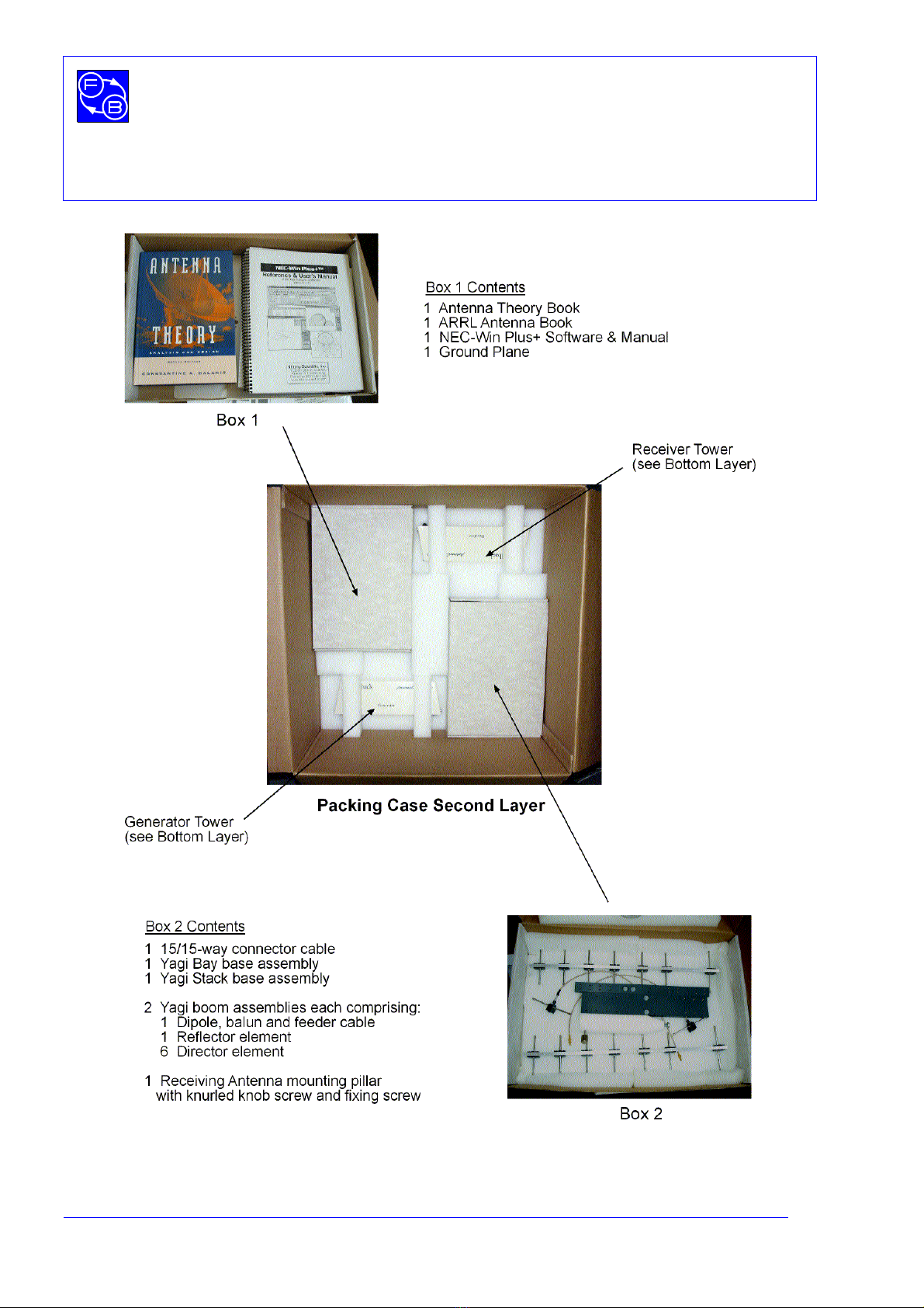
The equipment is supplied in a single package which is divided into three layers. The
contents of each layer are shown in Figures 1 to 3.
Figure 1: Packing Case Top Layer Contents
BoufoobMbc!
OPERATOR’S MANUAL Equipment List
2 57-200-USB
Figure 2: Packing Case Second Layer Contents
BoufoobMbc!
OPERATOR’S MANUAL Equipment List
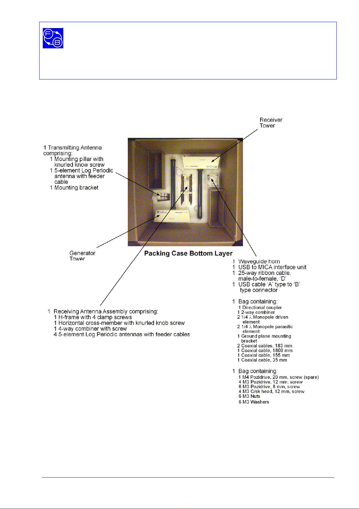
57-200-USB 3
Figure 3: Packing Case Bottom Layer Contents

BoufoobMbc!
OPERATOR’S MANUAL Equipment List
4 57-200-USB
Notes

Chapter 1
BoufoobMbc!
OPERATOR’S MANUAL Introduction to BoufoobMbc
57-200-USB 1-1
1 Introduction to BoufoobMbc
Understanding antennas is often thought of as a 'black art'. The theoretical study of
antennas can be mathematically demanding, requiring knowledge of electric field theory,
spherical geometry, calculus and other advanced mathematical concepts.
However, even armed with these mathematical tools, analysing the performance of
antennas in real, practical situations relies heavily on experience, as it is very difficult to
include all of the vagaries of an antenna's electrical and physical surroundings in
theoretical calculations.
Don't worry! The work done with BoufoobMbc is essentially non-mathematical in its
approach to the subject. The practical aspects and effects associated with antennas are
stressed and the software that is supplied along with BoufoobMbc takes care of the high-
level mathematics. The unique blend of hardware and software experimentation leads to a
practical understanding of antenna performance that would be difficult to achieve with
either hardware or software alone.
The 57-200 BoufoobMbc System comprises hardware, software and courseware, which
together form an integrated learning environment for the study of antenna principles.
BoufoobMbc is designed to explore antenna parameters, and operates between 1.2 and
1.8 GHz. Some background knowledge is necessary in order to make proper use of the
system. The system is complementary to another Feedback product, the ASD512 Antenna
Systems Demonstrator, which deals with the basic concepts of voltage and current in
radiating elements. The 57-200 takes these ideas and puts them into practice, introducing
the user to the concept of computer-based antenna measurements. The 57-200 is
designed to be used at almost any teaching level and, when operated in a low-reflection
environment, is capable of producing data suitable for research and development.
The following parameters can be measured:
•Directivity and gain, displayed as polar diagrams.
•Bandwidth, displayed as graphs of amplitude against frequency.
•Matching, displayed as graphs of return loss against frequency.
A directional coupler is provided for the return loss measurements.
Data may be recorded for archive or for playback on another computer not connected to
the 57-200 hardware.

Chapter 1
BoufoobMbc!
OPERATOR’S MANUAL Introduction to BoufoobMbc
1-2 57-200-USB
Notes

Chapter 2
BoufoobMbc!
OPERATOR’S MANUAL Installing BoufoobMbc
57-200-USB 2-1
2 Installing BoufoobMbc
2.1 Customers Upgrading from 57-200 to 57-200-USB
If you are upgrading from the earlier 57-200 to 57-200-USB, using the 57-202
BoufoobMbc Upgrade Pack, proceed as follows:
1. You may uninstall the DOS based 57-200 BoufoobMbc software (although this is
not necessary). However, please note that the plot files generated using 57-200
may not be used in 57-200-USB nor vice versa.
2. If you have uninstalled the 57-200 software and, if no other software installed on the
PC uses the MICA926 interface card, this can be uninstalled and removed.
3. Install the new software, following the instructions given on the software distribution
CD 57-903 and Feedback Manual – IMS Compatible Content, Installation and User
Guide 93-IMS.. It is important to do this before connecting hardware.
When prompted for hardware calibration values, these may be obtained by examining the
sysinfo.ini file that accompanied the 57-200 software. Earlier versions of the hardware do
not have the calibration values on the rear of the generator.
Once the software installation is complete, please refer to the section on installing the
hardware.
2.2 Installing the Software
Instructions describing how to install the software can be found on the software distribution
CD (57-903). For general information on how to install the software, refer to Feedback
Manual – IMS Compatible Content, Installation and User Guide 93-IMS.

Chapter 2
BoufoobMbc!
OPERATOR’S MANUAL Installing BoufoobMbc
2-2 57-200-USB
2.2.1 Installing the NEC-WIN Software
Installation instructions for this software are given in the accompanying supplied manual.
2.3 Installing the Hardware
BoufoobMbc requires the use of a single USB port. You can identify a USB port on the
back of your computer as a narrow rectangular socket that is usually located close to an
existing keyboard connector.
IMPORTANT NOTE:
It is important that all software packages and components are installed BEFORE
any USB hardware is connected and switched on.
Connecting the USB hardware before installing the software causes ‘unknown
device’ messages to be displayed, since the computer will not know of the USB
devices.
If the hardware has been connected by accident, it should be uninstalled as
follows:
1. From the ‘Start’ menu select ‘Settings’ →‘Control Panel’ →‘System’.
2. Access the ‘Device Manager’ utility.
3. Select ‘View’ →‘Devices by type’.
4. In the Device Manager tree expand the ‘Other devices’ entry and select the
‘USB Device’ entry that has a question mark icon.
5. Right click on the entry and select ‘Uninstall’ (or ‘Remove’) and click OK.
Disconnect the USB hardware.
Reboot the computer.
Install appropriate software.
Reconnect the USB hardware to a different USB port.
When the computer is switched on, a normal ‘connection process’ will occur.
6. This procedure is appropriate to the Windows XP operating system;
however, it may differ for other operating systems

Chapter 2
BoufoobMbc!
OPERATOR’S MANUAL Installing BoufoobMbc
57-200-USB 2-3
2.3.1 Customers Upgrading from 57-200 to 57-200-USB
If you are upgrading from the earlier 57-200 to 57-200-USB, using the 57-202
BoufoobMbc Upgrade Pack, proceed as follows:
1. The cable from the MICA8 card to the generator is not required when using 57-200-
USB and should be removed from the system. (Though this cable should be
retained if you think you may use the 57-200 software again.)
2. Proceed as directed in the following sections.
2.3.2 Installing Feedback USB Devices
1. Before connecting hardware, install the driver software.
2. Ensure that the USB interface unit is not connected to any other device.
3. Connect the interface unit directly to a USB port on your computer using a
USB cable.
The operating system should detect that a USB device has been connected to the
computer and the installation should proceed automatically as shown in Figure 2-1.
Figure 2-1
During the installation, you may be prompted one or more times for the path where a ‘sys’
file is located, as in the following example (see Figure 2-2).
Figure 2-2

Chapter 2
BoufoobMbc!
OPERATOR’S MANUAL Installing BoufoobMbc
2-4 57-200-USB
If this is the case, specify one of the following (depending on your operating system):
Operating system Sys file path
Windows 98, ME C:\windows\system32\drivers
Windows 2000, XP C:\winnt\system32\drivers
(Where 'C:' is the drive where your operating system is installed.)
Once your computer has completed the installation, your USB device is ready for use. It is
not necessary to remove the case of your computer or adjust any switches.
Once the USB interface units are installed, you may then connect the workboards.
2.4 Hardware Setup
The measurement accuracy of the 57-200, as of all antenna testing systems, is affected by
reflections from its surroundings. In order to obtain the highest performance, an open field
site or anechoic chamber would be necessary; however, excellent results for teaching can
be obtained in a typical laboratory. The design separation between the two antennas is 3
metres. If very high gain antenna systems were being tested, then a greater distance
would be needed to obtain the plane wavefront necessary to give accurate results.
Conversely in a difficult situation with low gain antennas and high levels of room reflection,
closer separation can be tolerated. Situations where good reflectors, such as metal, are in
close proximity should be avoided.
Place the generator tower, 57-200 Generator on a table or bench where it is about one or
two metres from the computer. The receiver tower, 57-200 Receiver, should be located
about three metres from the generator tower. It is not advisable to have the computer
between the two, as there should be as much space as possible around the two towers in
order to reduce reflections.
2.4.1 Connecting the Computer
It is important that you install the 57-903 BoufoobMbc USB driver software before
you connect the hardware to the computer.
Once the driver software is installed and the USB interface unit connected to the
computer, connect the interface unit to the computer socket on the generator tower using
the 25-way ribbon cable. You can fit it only one way round and into only one of the sockets
on the tower base.

Chapter 2
BoufoobMbc!
OPERATOR’S MANUAL Installing BoufoobMbc
57-200-USB 2-5
2.4.2 RF Connections
Connect the RF coaxial cable emerging from the base of the generator tower to the
adjacent RF out socket.
Connect the RF coaxial cable emerging from the base of the receiver to the adjacent RF in
socket.
2.4.3 Connecting the two Towers Together
The 15-way sockets on the two towers should be inter-connected using the cable
assembly provided. It does not matter which way round the cable is fitted.
2.4.4 Connection to the Mains Supply
Check that the line voltage selector, mounted on the back of the 57-200 Generator unit, is
set to the correct value for your supply. Set the Power and Motor Enable switches off.
Connect the Line socket to the mains using the lead provided making sure the mains
earth is properly connected.
2.4.5 Receiver Antenna
This is an array of four 5-element log periodics fed to a four-way microstrip combiner. It is
illustrated in Figure 2-3.
This antenna is used in all the measurements and tests described in the software and is a
suitable receiving antenna for most Antenna Tests.
The Receiver Antenna is supplied assembled and should not normally need to be
dismantled. However, should you wish to alter the assembly to provide a different antenna,
instructions for its re-assembly are given in the following paragraphs.

Chapter 2
BoufoobMbc!
OPERATOR’S MANUAL Installing BoufoobMbc
2-6 57-200-USB
Figure 2-3: Receiving Antenna
a) View from above
b) View from Front
clamp screw

Chapter 2
BoufoobMbc!
OPERATOR’S MANUAL Installing BoufoobMbc
57-200-USB 2-7
2.4.6 Assembly
Figure 2-4: Assembling the H-frame
The first stage in assembly is to attach the H-frame to the horizontal bar which is in turn
attached to the mounting pillar, as shown in Figure 2-4. The combiner, Figure 2-5, is then
attached to the free end of the horizontal bar (see also Figure 2-6).
4 coaxial sockets for
antenna elements
coaxial socket for
receiver connection
Figure 2-5: The Combiner
Assemble the log-periodic assemblies to the H-frame as indicated in Figure 2-3, making
sure that the four antennas are correctly phased; ie, that the individual log-periodics all
have the cables emerging at the top (or all at the bottom) and that each element points the
same way as the corresponding ones in the other log-periodics.
Table of contents
Other feedback Laboratory Equipment manuals

Popular Laboratory Equipment manuals by other brands


EYELA
EYELA N-1300 Series instruction manual

IKA
IKA A10 basic operating instructions

REPLIGEN
REPLIGEN TangenX SC Series user guide

Gamry Instruments
Gamry Instruments PTC1 Operator's manual

Stuart
Stuart SW6 Instructions for use

VERDER
VERDER Carbolite Gero HTMA 5/95 Installation, operation and maintenance instructions