Feelgood mr.steam iTEMPO Instruction manual

mr
.steam® Feel Goo Inc.
www.mrsteam.com
iTEMPO™& iTEMPO/PLUS™CONTROLS
Installation, Operation & Maintenance Manual

General In ormation
As you follow these instructions, you
will notice warning an caution
symbols. This blocke information is
important for the safe an efficient
installation an operation of this
control. These are types of potential
hazar s that may occur uring
installation an operation:
states a hazar
may cause serious injury or eath
if precautions are not followe .
signals a situation
where minor injury or pro uct
amage may occur if you o not
follow instructions.
IMPORTANT NOTE:
This highlights information that is
especially relevant to a problem-free
installation.
WARNING
!
Table o Contents:
General Information.........................................1
Before Installing ............................................1-2
Dimensional Information..................................3
Installations ...................................................4-7
Installing the Remote
Temperature Probe ...................................8-10
iTempo Operating Instruction...................11-12
iTempo/Plus Operating Instruction...........13-16
Care an Maintenance...................................17
Warranty .........................................................17
CAUTION
!
mr.steam®
Sussman-Automatic Corporation®I [email protected] I www.mrsteam.com
43-20 34th Street, Long Islan City, NY 11101 9410 S. La Cienega Blv . Inglewoo CA 90301
1 800 76 STEAM FAX: 718 472 3256 1 800 72 STEAM FAX: 310 216 2944

1
mr
.steam®Installation & Operating Instructions
_____________________________________________________________
BEFORE INSTALLING
Carefully inspect the control an packaging
for shipping amage. In the event of ship-
ping amage, please contact the carrier for
claim information. Our customer service e-
partment can assist you with any missing or
amage parts.
To avoi unintentional steam-
bath operation, o not locate the control
where other controls, accessories, shower
hea s, valves, bo y sprays or similar within
the shower coul cause confusion or inter-
fere with the Mr.Steam control’s inten e
use an function.
Do not use any iTempo/Plus, iTempo, Home-
Wizar or iGenie controls without rea ing
an un erstan ing the respective Installation
an Operation Manual an Mr.Steam steam
generator Installation an Operation Manual
(PN 101289 Revision number 10.0/08 or
higher). Failure to rea an un erstan
these instructions may result in an inopera-
tive or hazar ous installation.
CAUTION
!
WARNING
!
A peel an stick warning
sticker is provi e in the MrSteam steam
generator Installation, Operation an Main-
tenance Manual. This manual is provi e
with every steam generator. The warning
sticker must be rea an permanently affixe
in a conspicuous location near the steam
room. Failure to rea an affix this warning
sticker in a conspicuous location may result
in serious injury or eath. Please call
MrSteam at 800 767-8326 for a free replace-
ment or if you have any questions regar ing
the warning sticker.

mr
.steam®Installation & Operating Instructions
______________________________________________________________
2
BEFORE INSTALLING (cont.)
Install the iTempo or iTempo/Plus controls ac-
cor ing to installation instructions. Failure to
install accor ing to instructions will result in
an inoperative control or hazar ous overheat-
ing or ina equate heating of the steam
room. If an iTempo or iTempo/Plus control is
installe outsi e the steam room a Remote
Temperature Probe (PN MSTS) must be in-
stalle insi e the steam room per instructions
for the Remote Temperature Probe. Failure to
install accor ing to instructions will result in
an inoperative control an overheating of the
steam room.
Do not route iTempo/Plus,
iTempo, Home Wizar or iGenie control
wiring insi e con uit together with power
lines or close to hot water or steam piping.
Doing so may result in an inoperative or haz-
ar ous installation. Do not alter or mo ify
any Mr. Steam pro ucts inclu ing the steam
generator, iTempo/Plus, iTempo, iGenie or
Home Wizar controls. Doing so may result
in an inoperative or hazar ous installation
an will voi the warranty.
WARNING
!
IMPORTANT NOTES:
• Turn power to the steam generator OFF be-
fore connecting the control to the generator.
Failure to turn the power off will result in an
inoperable control.
• Do not operate iTempo/Plus, iTempo, Home
Wizar or iGenie controls with anything other
than a Mr.Steam iTempo compatible steam
generator. Mr.Steam resi ential steam genera-
tors with serial numbers lower than 900000, or
any other bran of steam generator are not to
be operate with iTempo controls. Doing so
may result in an inoperative installation.
• This ocument contains important safety,
operation an maintenance information.
Leave this ocument with the homeowner.
Do not iscar this ocument.
• Discontinue use of the steam generator
or control if the steam generator is amage
or otherwise not functioning properly. Doing
so may result in an inoperative or hazar ous
installation.
• All illustrations are for illustrative purposes
only.
21
/2”
41
/2”
1
/4”
3/8”
3/4”
1”
5”
5”
33/4”
12” long
pigtail
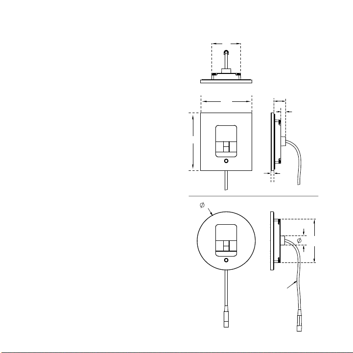
Dimensional In ormation
or the Round and Square
iTempo™and iTempo/Plus™
BOX CONTENTS:
• iTempo™or iTempo/Plus™Control
• Control Cable (30 ft.)
• Steam hea
• Tube of Silicone Sealant
• Owner’s Manual
3
mr
.steam®Installation & Operating Instructions
______________________________________________________________
Drawings for Ill strative P rposes Only.

4
mr
.steam®Installation & Operating Instructions
______________________________________________________________
IMPORTANT NOTE:
See installation instructions for
the MSTS Temperature Probe
before rough-in or installation
of control (pg. 8-9).
Ins alla ion Ins ruc ions for Round &
Square iTempo™and iTempo/Plus™
STEP 1
Determine the desired installation location of the control.
The iTempo™and iTempo/Plus™ controls are designed to
be installed inside or outside the steam room as a
matter of personal preference. If the control is
installed outside the steam room a Remote Temp-
erature Probe part number MSTS must be installed
inside the steam room. If the control is installed
inside the steam room the control must be located:
• 4-5 feet above the floor near the bather seating
area.
• The control features an integral temperature
sensor. Locate the control in a location repre-
presentative of the desired steambathing
temperatures. Do not locate the control above or
near the steam head or direct steam emissions. Locating
the controls near the steamhead or near direct steam
emissions may result in poor steam room temperature control.
• On a vertical wall
• The control cable length is 30 feet. Insure that the control
and/or steam generator are located accordingly.
Contact a Mr.Steam technical service representative if a
longer cable is required (60 ft. cable, PN 103990-60).
3-7
⁄ 8”
Drawings for Illustrative Purposes Only.
DIAGRAM 1
2-5
⁄ 8”
STEP 2
Diagram 1
Ma e a 2-5
⁄8” wide by 3-7⁄8” high cutout in
the desired control location.
Do not oversize or undersize the cutout.
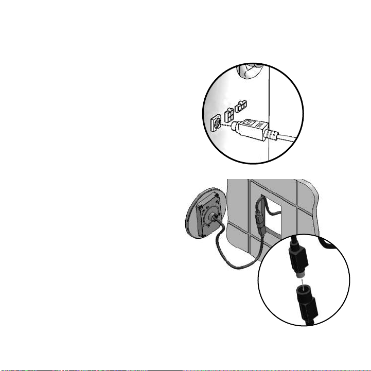
STEP 3
Diagram 2
Route the control cable (provided with the
control) from the wall cutout to the steam
generator. Connect one end of the cable to
the steam generator connector.
NOTE:
The connector is eyed with the
flat facing up. The control cable is the same
at both ends.
IMPORTANT NOTE:
Be careful not to
strain, staple, pinch or otherwise damage
the control cable. Route cable as required
to permit replacement. Do not route cable
inside conduit together with power lines or
close to hot water or steam piping.
STEP 4
Diagram 3
Firmly connect the other end of the cable to
the control. Turn on power to the steam
generator and test the control to verify
correct connections. Test per the
instructions on pages 10-15. With
verification of proper control function,
proceed to Step 5.
DIAGRAM 2
mr
.steam®Installation & Operating Instructions
______________________________________________________________
5
Drawings for Illustrative Purposes Only.
DIAGRAM 3

If the generator is on for more
than a few minutes steam will start coming out
of the steamhea . Insure that steamroom is not
occupie .
STEP 5
Diagram 4
Remove an iscar peel-off paper to expose
a hesive liner.
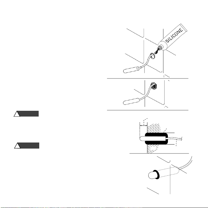
STEP 6
Diagram 5
Run a bea of silicone (provi e ) as shown to
the outer e ge of the control faceplate,
following the contour of the circle or square
shape. Use silicone as require to create a
moisture seal.
NOTE: The silicone supplie by Mr. Steam can
be use to meet a variety of sealing an
gasketing. It cures to silicone rubber an
a heres to glass, woo , metal, porcelain,
ceramic tile, painte surfaces, many plastics an
rubber. Surfaces must be clean an ry. Apply
thin layer of pro uct. Fit together an support if
necessary. Allow excess material to cure, then
trim with a sharp bla e. Sealant “skins” in 5
minutes, ries to touch in 1 hour. Fully cures an
bon s in 24 hrs.
DIAGRAM 5
mr
.steam®Installation & Operating Instructions
______________________________________________________________
6
DIAGRAM 4
CAUTION
!
Drawings for Ill strative P rposes Only.
mr
.steam®Installation & Operating Instructions
______________________________________________________________
IMPORTANT NOTE:
Do not apply
excessive amo nts of silicone. Do not apply
silicone to any other parts of the control
incl ding the adhesive gasket.
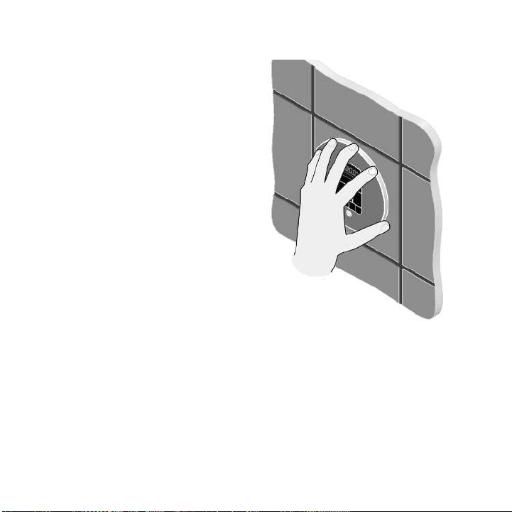
STEP 7
Diagram 6
Insure the mounting surface is clean an ry
as require for goo a hesion. Hol the
control with the LED isplay in the 12 o'clock
position an press the control against the wall
u ntil the a hesive sticks an hol s firmly.
Control may have to be supporte or secure
until the silicone fully cures an bon s.
7
DIAGRAM 6
Drawings for Ill strative P rposes Only.

Installing the Remote
Temperature Probe
(PN: MSTS)
The Remote Temperature Probe is require
when the iTempo or Tempo/Plus Controls
are installe outsi e the steam room.
The Remote Temperature
Probe (P/N MSTS) is for use with iTempo
an iTempo/Plus Controls only. Do not use
with any other controls. Do not use any
other temperature probe with the iTempo
an iTempo/Plus controls. Noncompatible
pro ucts may result in an inoperative con-
trol an a hazar ous con ition.
Install the iTempo or
iTempo/Plus controls accor ing to the in-
stallation instructions on pages 3-5. Failure
to o so may result in an inoperative con-
trol an a hazar ous con ition.
1. Determine the location of the Remote
Temperature Probe:
The Remote Temperat re Probe m st be
installed
:
a. On a vertical surface
b. 4-5 feet above the floor
c. in a location representative of the esire
steam bathing temperature. Locating the MSTS
near the steamhea or near irect steam emis-
sions may result in poor steamroom temperature
control.
d. The probe has an integral 30' cable. Insure that
the probe an /or steam generator are locate ac-
cor ingly.
2. Drill a 5/16 inch iameter hole in the wall. Do
not oversize or un ersize the hole. Clean area
thoroughly.
NOTE: The silicone supplie by Mr. Steam can be
use to meet a variety of sealing an gasketing. It
cures to silicone rubber an a heres to glass,
woo , metal, porcelain, ceramic tile, painte sur-
faces, many plastics an rubber. Surfaces must be
clean an ry. Apply thin layer of pro uct. Fit to-
gether an support if necessary. Allow excess mate-
rial to cure, then trim with a sharp bla e. Sealant
“skins” in 5 minutes, ries to touch in 1 hour. Fully
cures an bon s in 24 hrs.
3. Remove the knock-out from the steam
generator jacket as shown in Diagram 1.
4.
Insert the probe cable through the knock-out an
connect to the connector on the steam generator
printe circuit boar marke EXT TEMP as shown in
Diagram 1.
CAUTION
!
CAUTION
!
mr
.steam®Installation & Operating Instructions
______________________________________________________________
8

9
mr
.steam®Installation & Operating Instructions
______________________________________________________________
Mr.Steam Steam Generator
(shown with cover removed
and NOT installed)
Temperature
Probe Cable
(30 feet)
Temperature
Probe Connection
Knock-Out
Temperature
Sensor Probe
DIAGRAM 1
Drawings for Ill strative P rposes Only.
mr
.steam®Installation & Operating Instructions
______________________________________________________________
10
5.
Route the en of the probe cable with the tem-
perature probe through the wall into the steam
room as shown in Diagram 2.
IMPORTANT NOTE:
Do not strain, staple,
pinch or otherwise amage the probe cable.
6. With a minimal length of the cable expose
apply silicone (provi e ) to the hole in the wall
as require to create a moisture seal as shown
in Diagram 2.
7. Push the temperature cable an probe into
hole as require to leave minimum 1/4",
maximum 1/2" of the bulb expose as shown
in Diagram 3.
Insure a minimum of 1/4" of
the temperature probe is expose to the air.
Failure to o so may interfere with the ability
to sense temperature an may result in
excessive steam room temperatures.
The expose area of the tempera-
ture probe must be free of silicone or any materials
or obstructions that prevent irect exposure to the
steam room air. Failure to o so may interfere with
the ability to sense temperature an may result in
excessive steam room temperatures
.
NOTE:
For Ill strative P rposes Only.
Drawings Not to Scale
WARNING
!
WARNING
!
Silicone Sealant
Cable
Wall
1⁄4" minimum
1⁄2" maximum
DIAGRAM 2
DIAGRAM 3
Sectional View
Installed Remote
Temperature Probe
showing a minimum
of 1/4” of the probe
expose to steam-
room air
S T E A M R O O M I N T E R I O R

11
mr
.steam®Installation & Operating Instructions
______________________________________________________________
The iTempo Control features programmable igital
temperature control, a fixe (60) minute uration,
ON/OFF an PAUSE. The control can be set at a
temperature range from 80˚Fup to 120˚F
Set the steambathing temperature
accor ing to personal preference, however it is
highly recommen e to begin steambathing at a
low temperature setting for a very short uration to
gauge comfort an safety levels.
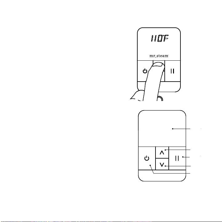
ON/OFF
Diagram 1
Press the ON/OFF key to start or stop the flow of
steam. Steam will begin to flow a few minutes after
the control is turne ON. The uration require for
the steam room to reach steambathing tempera-
tures epen s on the steam room construction an
steam generator specifications. Steam may continue
to flow for a short time after the control is turne
OFF.
PAUSE FEATURE
Diagram 2
If a pause in steam flow is esire press the PAUSE
key. The isplay will flash while the control is in the
PAUSE mo e. The timer will continue to count own
while in the PAUSE mo e. Steam may continue to
flow for a short time after pause is presse .
DIAGRAM 1
DIAGRAM 2
iTempo™Operating Instructions
WARNING
!
Drawings for Ill strative P rposes Only.
mr
.steam®Installation & Operating Instructions
______________________________________________________________
12
DIAGRAM 3
Display
Up Key
Pause Key
Down Key
ON/OFF
Key
mr.steam
DIAGRAM 4
TIMER FEATURE
When the control is turne ON a 60 minute time u-
ration is initiate . The control will turn off after 60
minutes unless the control is turne off manually.
MEMORY FEATURE
If the control is turne off manually before 60 minutes
then the efault temperature of 110˚F will be use
the next time the control is turne on. If the control
times out at 60 minutes (not manually turne off) then
the previous user temperature setting will be use
when the steambath is use again.
SETTING THE TEMPERATURE
Diagram 3
The control is pre-set an will isplay the temperature
setting of 110˚F ( efault setting). Use the UP an
DOWN keys to change the temperature setting from
80˚ F to 120˚ F in one egree increments.
CHANGING THE TEMPERATURE UNITS
(F˚/C˚) Diagram 4
When the generator is Off, Press an hol ON/OFF
key for 10 secon s. The temperature units will be is-
playe as Fahrenheit (TuF) or Celsius (TuC). Use the
UP/DOWN keys to choose between (TuF) an (TuC).
Press ON/OFF key to accept the new units an exit.
Drawings for Ill strative P rposes Only.

13
mr
.steam®Installation & Operating Instructions
______________________________________________________________
mr.steam
temp
aroma chroma
time
mr.steam
temp
aroma chroma
time
The iTempo/Plus Control features programmable tempera-
ture control, programmable time uration, clock, Aroma-
Steam, ChromaSteam®, ON/OFF an two personal settings.
Set the steambathing temperature accor ing
to personal preference, however it is highly recommen e
to begin steambathing at a low temperature setting for a
very short uration to gauge comfort an safety levels.
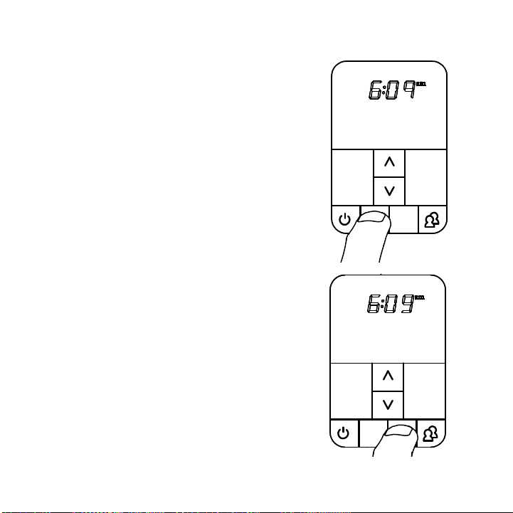
POWERING UP THE UNIT
Diagram 1
When the generator is first powere up or after a power
interruption, the clock isplay flashes an the clock is
rea y to be set up.
NOTE:
Pressing the ON/OFF will start the generator
even if the clock has not been set.
ON/OFF
Diagram 2
Press the ON/OFF key to start or stop the flow of steam.
The Temperature Set Point is isplaye . Steam will begin to
flow a few minutes after the control is turne ON. The
uration require for the steam room to reach steambathing
temperatures epen s on the steam room construction an
steam generator specifications. Steam may continue to flow
for a short time after the control is turne OFF.
iTempo/Plus™Operating Instructions
WARNING
!
DIAGRAM 1
DIAGRAM 2
Drawings for Ill strative P rposes Only.

mr
.steam®Installation & Operating Instructions
______________________________________________________________
14
iTempo/Plus™Operating Instructions
(cont.)
mr.steam
temp
aroma
SETTING THE CLOCK
Diagram 3
When the isplay is not flashing: Press an hol the
TIME key until the isplay starts flashing.
Use the UP/DOWN keys to select the esire time,
at this time the AM/PM logo will be isplaye .
Press the TIME key to save changes.
NOTE:
The clock can only be set when the
generator is off.
SETTING THE STEAMBATH DURATION
Diagram 4
Press TIME key to set or isplay the steambath ura-
tion time on the clock. The control is pre-set an will
isplay a TIME setting of 20 minutes ( efault set-
ting). With the TIME or CLOCK isplaye , press the
UP or DOWN keys (Diagram 5) to set the esire
uration time (2-60 minutes) in two minute incre-
ments.
Set the steambath uration accor ing to personal
preference, however it is highly recommen e to
begin steambathing at a very short uration to
gauge comfort an safety levels. The control will
turn off when the uration perio times out. Then,
the clock time will be isplaye .
DIAGRAM 3
DIAGRAM 4
DIAGRAM 5

15
mr.steam
aroma chroma
time
mr.steam
chroma
timetemp
aroma chroma
mr.steam
timetemp
SETTING THE TEMPERATURE
Diagram 6: Press TEMP key to set the esire temperature or is-
play the temperature setting.
Diagram 7: The control is preset an will isplay a temperature
setting of 110˚F ( efault setting). With the temperature isplaye ,
press the UP or DOWN keys to set the esire temperature (80°F
to 120°F) in one egree increments.
Set the steambathing temperature accor ing to personal prefer-
ence, however it is highly recommen e to begin steambathing at
a low temperature setting to gauge comfort an safety levels.
MEMORY FEATURE
If the control is turne off manually before it times out then the
efault settings of 20 minutes an 110°F will be use the next
time the control is turne on. If the control times out (not manually
turne off) then the previous user time an temperature settings
will be use when the steambath is turne on.
PROG 1 AND PROG 2
Diagram 8
Use the P1/P2 key program to store preferre settings.
To program preferre settings:
Press ON/OFF key to turn generator on.
Press P1/P2 key once to program PROG1.
Press it twice to program PROG2. The selecte parameter will be
isplaye . Enter the preferre time an temperature settings.
The iTempo/Plus will store the following settings: set point, time
uration & aroma state. To select PROG1 or PROG2 : Press
ON/OFF key then press P1/P2 key once to select PROG1,
press it twice to select PROG2. The steambath will begin
to operate at the store settings.
DIAGRAM 6
DIAGRAM 7
DIAGRAM 8
mr
.steam®Installation & Operating Instructions
______________________________________________________________
mr
.steam®Installation & Operating Instructions
______________________________________________________________
16
mr.steam
chroma
timetemp
aroma
mr.steam
aroma
timetemp
chroma
CHANGING THE TEMPERATURE
UNITS
(˚F/˚C)
When the generator is Off, Press an hol
ON/OFF key for 10 secon s. The temperature
units will be isplaye as Fahrenheit (TuF) or
Celsius (TuC). Use the UP/DOWN keys to
choose between (TuF) an (TuC). Press
ON/OFF key to accept the new value an exit.
AROMASTEAM
Diagram 9
The AromaSteam is an optional accessory
that automatically injects aromatic oil into
the steam. Press the ON/OFF key to turn the
steam generator on. Then, press the
AROMA key. The Aroma in icator will be
isplaye . The AromaSteam turns off auto-
matically when the steam generator stops
heating. Press the AROMA key to turn it off
uring a steam session. The in icator will
turn off.
CHROMASTEAM
™ Diagram 10
The ChromaSteam is an optional accessory
that provi es colore light in the steam-
room. Press the CHROMA key to turn light
on. Press twice to select the next color. Press
again to turn the light off. Note that the light
can be turne ON even if the steam genera-
tor is OFF.
DIAGRAM 9
DIAGRAM 10

17
mr
.steam®Installation & Operating Instructions
______________________________________________________________
Care Tips or all Controls and Steamheads
1. Use only mil soap an water on a soft cloth to clean the control an steamhea .
2. Do not use abrasive cleansers
3. If the ecorative cover is amage on the iTempo™or iTempo/Plus™
call Mr.Steam®technical service for replacement parts.
NOTE:
Replacement of the ecorative covers requires removal an
reinstallation of the control from the mounting surfaces.
Warranty
To register your steam generator unit online an
to review the Mr.Steam Limite Lifetime Warranty please go to:
blog.mrsteam.com/wr
mr.steam
temp
aroma chroma
time
Display
Up Key
Time Display/
Adjust Key
Down Key
Program Key
ChromaSteam
Key
Time Display/
Adjust Key
ON/OFF Key
AromaSteam
Key

mr
.steam®
Feel Goo Inc.
Pro ucts, information an
specifications are subject
to change without notice.
For more information
call Sales & Support at:
1.800.76.STEAM
(East Coast)
1.800.72.STEAM
(West Coast)
2013 © Sussman-Automatic Corporation
Mr.Steam an es., AromaFlo, AutoFlush, Au-
toSteam, Butler Package, ChromaSteam, Clean
Steam...Every Time, Club Therapy, Digital 1,
Express Steam, From Bathroom to Spa, iSizing,
iSteam, iSteam/Plus, MusicTherapy, Spa Pack-
age, Steam Genie, Steam on Deman ,
Steam@Home, iTempo, iTempo/Plus, Steam
Therapy, Sussman, Valet Package, Virtual Spa
System, Voice Genie an Voice Wizar are reg-
istere tra emarks of Sussman-Automatic Cor-
poration. Au ioWizar , Home Wizar , iButler,
iGenie, iTempo, iTempo/Plus, MySteam, Smart
Sizing, SteamStart, SteamStop, The Intelligent
Steambath are tra emarks of Sussman-
AutomaticCorporation. 100474 REV. 2/13
TEMPLATE FOR CONTROL INSTALLATION (SEE PG.4)
3-7
⁄ 8”
2-5⁄ 8”
This manual suits for next models
1
Table of contents


