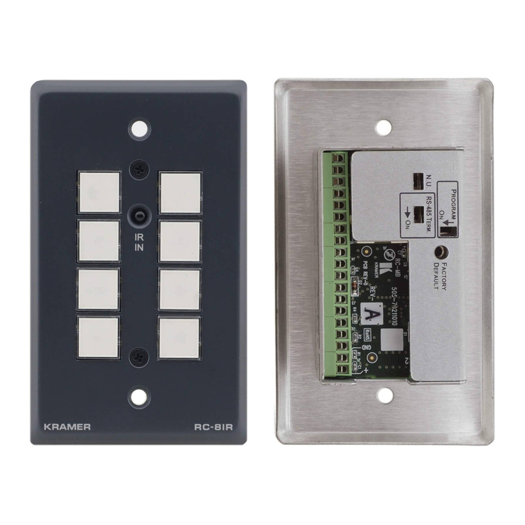
Kramer K-NET RC-53D User manual

Kramer Electronics, Ltd.
USER MANUAL
Model:
RC-53D
K-NET™ Auxiliary Control Panel

Contents
i
Contents
1Introduction 1
2Getting Started 1
3Overview 2
4Defining the RC-53D 3
5Using the RC-53D K-NET Auxiliary Control Panel 5
6Installing the RC-53D Faceplate, Button Caps and Labels 6
7Operating the RC-53D K-NET Auxiliary Control Panel 7
8Technical Specifications 8
Figures
Figure 1: RC-53D K-NET Auxiliary Control Panel – Front Panel 3
Figure 2: RC-53D K-NET Auxiliary Control Panel – Rear Panel 4
Figure 3: RC-53D connected to the SV-551 SummitView™ Processor / Switcher 5
Figure 4: Sample Button Label Sheet 6
Figure 5: Button Cap Orientation 6
Figure 6: RC-53D Labels Setup 7
Tables
Table 1: RC-53D K-NET Auxiliary Control Panel – Front Panel Features 3
Table 2: RC-53D K-NET Auxiliary Control Panel – Rear Panel Features 4
Table 3: The Commands Configuration 7
Table 4: Technical Specifications of the RC-53D K-NET Auxiliary Control Panel 8

Introduction
1
1 Introduction
Welcome to Kramer Electronics! Since 1981, Kramer Electronics has been providing
a world of unique, creative, and affordable solutions to the vast range of problems
that confront the video, audio, presentation, and broadcasting professional on a daily
basis. In recent years, we have redesigned and upgraded most of our line, making the
best even better! Our 1,000-plus different models now appear in 11 groups1
Congratulations on purchasing your Kramer RC-53D K-NET™ Auxiliary Control
Panel which is available in European (80mm and 86mm height versions) and
American versions, and can be used as a system controller when connected via
K-NET™
that are
clearly defined by function.
2
The package includes the following items:
to a Master room controller (for example, the SV-552 SummitView™
Processor / Switcher or one of the Kramer SL series controllers).
•The RC-53D
•Screwdriver
•This user manual3
2 Getting Started
This user manual is written for the end user. Refer to the separate
K-Config Configuration Guide (available online) for details of how to
install and configure the Room Controller4
We recommend that you review the contents of this user manual.
1 GROUP 1: Distribution Amplifiers; GROUP 2: Switchers and Matrix Switchers; GROUP 3: Control Systems; GROUP 4:
Format/Standards Converters; GROUP 5: Range Extenders and Repeaters; GROUP 6: Specialty AV Products; GROUP 7: Scan
Converters and Scalers; GROUP 8: Cables and Connectors; GROUP 9: Room Connectivity; GROUP 10: Accessories and Rack
Adapters; GROUP 11: Sierra Products
2 K-NET is a proprietary Kramer protocol for communication between Kramer products
3 Download up-to-date Kramer user manuals from http://www kramerelectronics com
4 The guide provides information about how to set up the system and is updated on a regular basis For the latest online guide, go to
http://www kramerelectronics com
KRAMER: SIMPLE CREATIVE TECHNOLOGY
Overview
2
3 Overview
The RC-53D is an auxiliary remote control panel for Master Room Controllers1
The RC-53D:
for
control of A/V equipment in a room.
•Features six front panel, single color, backlit buttons designed in two groups;
one group of two buttons, and another group of four buttons
•Has a digital volume control adjustment knob
•Is available as a 2 Gang wall plate for the USA or a 2 Gang wall plate for
Europe2
•Does not require a separate power supply
•Includes two K-NET ports and an RS-232 serial port for firmware upgrade
•Features two programmable LCD displays, one for each button group
To achieve the best performance:
•Connect only good quality connection cables, thus avoiding interference,
deterioration in signal quality due to poor matching, and elevated noise-levels
(often associated with low quality cables)
•Avoid interference from neighboring electrical appliances and position your
Kramer RC-53Daway from moisture, excessive sunlight and dust
1 Such as the Kramer SummitView System or the SL-1 Master Room Controller
2 Available in two height sizes: 8 6cm and 8cm

Defining the RC-53D
3
4 Defining the RC-53D
Figure 1and Table 1define the RC-53D front panel.
Version for the US Version for Europe
1 12 23 33 34 45 56 67 7
Figure 1: RC-53D K-NET Auxiliary Control Panel – Front Panel
Table 1: RC-53D K-NET Auxiliary Control Panel – Front Panel Features
# Feature Function
1 SOURCE Buttons Group of four programmable, backlit buttons
1
2
Faceplate Screws Four screws connecting the faceplate to the Rear Box
3 “DISPLAY” and “SOURCE”
Labels Programmable, 8 character, LCD displays on a blue background
4 DISPLAY Buttons Group of two programmable, backlit buttons
5 Maximum VOLUME LED Lights red, indicating maximum volume
6 VOLUME LEDs Light green, indicating volume level
7 VOLUME Knob Rotate clockwise to increase volume level
1 By the system integrator only

KRAMER: SIMPLE CREATIVE TECHNOLOGY
Defining the RC-53D
4
Figure 2and Table 2define the RC-53D rear panel.
Version for the US
Version for Europe
Figure 2: RC-53D K-NET Auxiliary Control Panel – Rear Panel
Table 2: RC-53D K-NET Auxiliary Control Panel – Rear Panel Features
# Feature Function
1 Program USB Connector Connect to a computer for firmware upgrade
1
2
Grounding Screw Connect to grounding wire
3 RS-232 Terminal Block Connect to the RS-232 connector on a PC for firmware upgrade
1
4 K-NET Terminal Block Connect the GND to the Ground connection2
5 , connect B (-) and
A (+) to RS-485, and connect +12V to +12V on the companion
unit
K-NET Terminal Block
1 When the unit is connected via K-NET to a Master Room Controller, you can upgrade the firmware via the USB or ETH ports of the
Master Room Controller
2 The ground connection is sometimes connected to the shield of the RS-485 cable (in most applications, it is not connected)

Using the RC-53D K-NET Auxiliary Control Panel
5
5 Using the RC-53D K-NET Auxiliary Control Panel
The installation process is not detailed in this user manual. This user manual is
applicable once the unit is installed and configured1
•Setting up the labels on the buttons, according to your specific requirements
, and includes:
•Configuration of the Master room controller via the K-Config Windows®-based
configuration software
Since the auxiliary panel is used as a remote controller for Master Room
Controllers via the proprietary communication channel K-NET (as illustrated in
Figure 3):
•It requires only a K-NET connection to the Master Room controller
•A power supply unit is not required2
•The auxiliary panel can be programmed only via the Master Room controller
(for example, the Kramer SV-551 SummitView™ Processor/Switcher)
Black = GND
PINOUT
Red = +12V
Green = A
White = B
Figure 3: RC-53D connected to the SV-551 SummitView™ Processor / Switcher
1 By authorized Kramer technical personnel or by an external system integrator
2 Power supplies are sold separately Consult your Kramer dealer for details

KRAMER: SIMPLE CREATIVE TECHNOLOGY
Installing the RC-53D Faceplate, Button Caps and Labels
6
6 Installing the RC-53D Faceplate, Button Caps and Labels
This section describes how to install the faceplate, button caps and labels.
Figure 4illustrates a sample button label sheet.
Figure 4: Sample Button Label Sheet
To install the faceplate, button caps and labels:
1. Remove the required labels from the supplied button label sheet.
2. Hold the button cap so that it is oriented as shown in Figure 5with the
“wings” on the left and right sides, and insert the label inside the cap.
3. Repeat for all six caps.
4. Retaining the orientation, place the six button caps on the buttons of the
RC-53D.
5. Remove the protective foils from both sides of the Perspex windows.
6. Place the faceplate on the RC-53D so that the four screw mounting holes are
aligned.
7. Insert the four mounting screws and tighten with a screwdriver.
8. Install the volume control knob.
Figure 5: Button Cap Orientation

Operating the RC-53D K-NET Auxiliary Control Panel
7
7 Operating the RC-53D K-NET Auxiliary Control Panel
In the following example1Figure 6(illustrated in ), the auxiliary control panel is
labeled with specific functions and each button is programmed2to perform several
tasks3Table 3as defined in .
Table 3: The Commands Configuration
The Label The Macro Sequence
Figure 6: RC-53D Labels Setup
ON •Power up the projector
•Power up the DVD player
•Roll down the projector screen
•1 minute delay (for he projector to heat
up)
•The projector selects the DVD input
OFF •Power down the projector
•Stop the DVD player
•Power down the DVD player
•Stop the VCR
•Power down the VCR
•Roll up he projector screen
DVD •Stop the video player
•The projector selects the DVD input
•Play the DVD
VCR •Stop the DVD
•The projector selects the VCR input
•Play the VCR
VOLUME •Use the VOLUME knob to adjust he
audio level
1 This is only one example among numerous possibilities, each button can be programmed as required In this example, two buttons are
not assigned
2 By the technical installer
3 A macro sequence, including several commands per button, carried out one after the other

KRAMER: SIMPLE CREATIVE TECHNOLOGY
Technical Specifications
8
8 Technical Specifications
Table 4defines the technical specifications.
Table 4: Technical Specifications1
PORTS:
of the RC-53D K-NET Auxiliary Control Panel
2 K-NET on terminal block connectors; 1 RS-232 on terminal block connector, 1USB
connector
POWER SOURCE: 12V DC, 140mA over K-NET
FUSE: 500mA, FSMD 1812
DIMENSIONS: For the USA: 11.4cm x 2.6cm x 11.4cm (4.49" x 1.02" x 4.49", W, D, H)
For Europe: 15.2cm x 1.9cm x 8.6cm (5.98" x 0.75" x 3.39", W, D, H) or
15.2cm x 1.9cm x 8cm (5.98" x 0.75" x 3.15", W, D, H)
WEIGHT: 0.14kg (0.31lbs.) approx.
ACCESSORIES: Screwdriver
1 Specifications are subject to change without notice

9
LIMITED WARRANTY
WHOISPROTECTED?
WHATISCOVEREDANDWHATISNOTCOVERED
WHATWEWILLPAYFORANDWHATWEWILLNOTPAYFOR
HOW YOU CAN GET WARRANTY SERVICE
LIMITATIONOFIMPLIEDWARRANTIES
EXCLUSIONOFDAMAGES
CAUTION!
Kramer Electronics (hereafter ) warrants this product free from defects in material and workmanship under the
following terms Kramer
HOWLONGISTHE WARRANTY
Labor and parts are warranted for seven years from the date of the first customer purchase
Only the first purchase customer may enforce this warranty
Wewillpaylaborandmaterialexpensesforcovereditems Wewillnotpayforthefollowing:
Theliability of Kramer forany effective productsis limited to the repair or replacement of theproduct at ouroption Kramer shall
notbeliablefor:
Thiswarrantygivesyouspecificlegalrights,andyoumayalsohaveotherrights,whichvaryfromplacetoplace
AllproductsreturnedtoKramerforservicemusthavepriorapproval Thismaybeobtainedfromyourdealer
Thisequipmenthasbeentestedtodeterminecompliancewiththerequirementsof:
EN-50081: "Electromagneticcompatibility(EMC);
genericemissionstandard
Residential,commercialandlightindustry"
EN-50082: "Electromagneticcompatibility(EMC)genericimmunitystandard
Part1:Residential,commercialandlightindustryenvironment"
CFR-47: FCC* Rules and Regulations:
Part 15: “Radio frequency devices
Subpart B Unintentional radiators”
Except as below, this warranty covers all defects in material or workmanship in this product The following are not covered
bythewarranty:
1 Any product which is not distributed by Kramer, or which is not purchased from an authorized Kramer dealer If you are
uncertain as to whether a dealer is authorized, please contact Kramer at one of the agents listed in the Web site
www kramerelectronics com
2 Any product, on which the serialnumber has been defaced, modified or removed, or on which the WARRANTY VOID
TAMPERED sticker has been torn,
3 Damage,deteriorationormalfunctionresultingfrom:
i) Accident,misuse,abuse,neglect,fire, water,lightningorotheractsofnature
ii) Productmodification,orfailuretofollowinstructionssupplied withtheproduct
iii) RepairorattemptedrepairbyanyonenotauthorizedbyKramer
iv) Anyshipmentoftheproduct(claimsmustbepresentedtothecarrier)
v) Removalorinstallationoftheproduct
vi) Anyothercause,whichdoesnotrelatetoaproductdefect
vii)Cartons,equipmentenclosures,cablesoraccessoriesusedinconjunctionwiththeproduct
1 Removalorinstallationscharges
2 Costs of initial technical adjustments (set-up), including adjustment of user controls or programming These costs are the
responsibilityoftheKramerdealerfromwhomtheproductwaspurchased
3 Shippingcharges
1 To obtain service on you product, you must take or ship it prepaid to any authorized Kramer service center
2 Whenever warranty service is required, the original dated invoice (or a copy)must be presented as proof of warranty
coverage, and should be included in any shipment of the product Please also include in any mailing a contact name,
company, address, and a description of the problem(s)
3 For the name of the nearest Kramer authorized service center, consult your authorized dealer
All implied warranties,including warranties ofmerchantability and fitness for a particular purpose, arelimited in duration to
the length of this warranty
1 Damagetootherpropertycausedbydefectsinthisproduct,damagesbaseduponinconvenience,lossofuseoftheproduct,loss
oftime,commercialloss;or:
2 Anyother damages, whether incidental,consequential or otherwise Some countries maynotallowlimitations on how longan
implied warranty lasts and/or do not allow the exclusionor limitation of incidental or consequential damages, so the above
limitationsandexclusionsmaynotapplytoyou
Servicing the machines can only be done by an authorized Kramer technician Any user who makes changes or
modifications to the unit without the expressed approval of the manufacturer will void user authority to operate the
equipment
UsethesuppliedDCpowersupplytofeedpowertothemachine
Pleaseuserecommended interconnection cablesto connect the machineto other components
IF reattached, removed or otherwise interfered with
*FCCandCEapprovedusingSTPcable(fortwisted pairproducts)
NOTE:
Part1:

Kramer Electronics, Ltd.
Web site: www kramerelectronics.com
E-mail: info@kramerel.com
P/N: 2900-000567 REV 3
For the latest information on our products and a list of Kramer
distributors, visit our Web site www.kramerelectronics.com,
where updates to this user manual may be found.
We welcome your questions, comments and feedback.
Safety Warning:
Disconnect the unit from the power supply before
opening/servicing.
Caution
Other manuals for K-NET RC-53D
1
Table of contents
Other Kramer Control Panel manuals

Kramer
Kramer RC-712M User manual

Kramer
Kramer RC-52N User manual

Kramer
Kramer RC-53DLC User manual

Kramer
Kramer WSI-1VGA User manual

Kramer
Kramer RC-3TB User manual

Kramer
Kramer RC-308 User manual

Kramer
Kramer K-NET RC-53DLC User manual

Kramer
Kramer VP-747T User manual

Kramer
Kramer T-RC-8IR User manual

Kramer
Kramer VP-727T User manual