Feeney Feeney DesignRail 24V LED Lighting V2, User manual

1-800-888-2418 | www.feeneyinc.com 1
Rev: 09/21
DesignRail®24V LED Lighng (v2)
General Notes:
Drivers are available in a variety of waages. In general a driver should not exceed more than 80% of its rated output capacity.
(Example: 60W Driver = 60 x 0.8 = 48W Max).
Strip Lights require 1.44 was per foot. Aer determining the necessary length of strip lighng, calculate the waage and ensure
the driver being used has adequate capacity (example: 10’ = 10 x 1.44 = 14.4W). The maximum length of strip lighng that can be
connected in one run is 55 feet.
Building codes vary by locaon and jurisdicon. Consult all applicable codes before installing DesignRail® LED Lighng.DesignRail®
LED Lighng may not be suitable for every applicaon and it is the sole responsibility of the installer to ensure that DesignRail® LED
Lighng is used for its intended purpose.
WARNING: ELECTRIC SHOCK IS ALWAYS POSSIBLE WHEN WORKING WITH ELECTRICITY. THIS CAN CAUSE SERIOUS PERSONAL
INJURIES OR DEATH. ELECTRICAL SHORTS CAN ALSO CAUSE FIRES AND PROPERTY DAMAGE. ALWAYS MAKE SURE THE
ELECTRICAL OUTLET YOU ARE PLUGGING INTO IS GROUNDED.
Installaon Instrucons
1-800-888-2418 | www.feeneyinc.com2
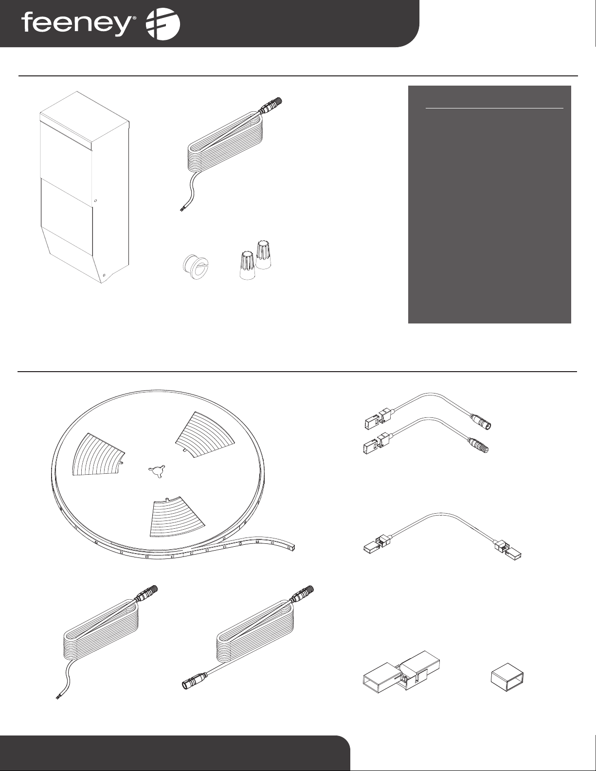
LED Lighng - Driver Kits
24V MAGNETIC DIMMABLE DRIVER
(SKU #LED : 40W, LED : 60W, LED : 96W)
ISOLATION
BUSHING
(SKU #1114)
WIRE NUTS
(PAIR)
(SKU #7670)
KIT CONTENTS
40W Driver Kit
(SKU #LED : 40W-DK)
1x 40 WaDimmable Driver
1x Starter Cable (20')
1x Wire Nuts (Pair)
1x Isolaon Bushing
60W Driver Kit
(SKU #LED : 60W-DK)
1x 60 WaDimmable Driver
1x Starter Cable (20')
1x Wire Nuts (Pair)
1x Isolaon Bushing
96W Driver Kit
(SKU #LED : 96W-DK)
1x 96 WaDimmable Driver
1x Starter Cable (20')
1x Wire Nuts (Pair)
1x Isolaon Bushing
LED Light Strip
(SKU #LED : 05 to LED : 55)
LED EXTENSION CABLE (132")
(SKU #LED : EXT132)
LED CONNECTOR PAIR (includes tube of silicone)
(SKU #LED : CONN)
LED CRIMP CONNECTOR (8")
(SKU #LED : CC8)
LED SPLICE CONNECTOR (5-pack)
(SKU #LED : SPL)
LED END CAP (5-pack)
(SKU #LED : EC)
LED STARTER CABLE (20')
(SKU #LED : STC)
LED Lighng - Components
LED STARTER CABLE (20')
(SKU #LED : STC)
1-800-888-2418 | www.feeneyinc.com 3
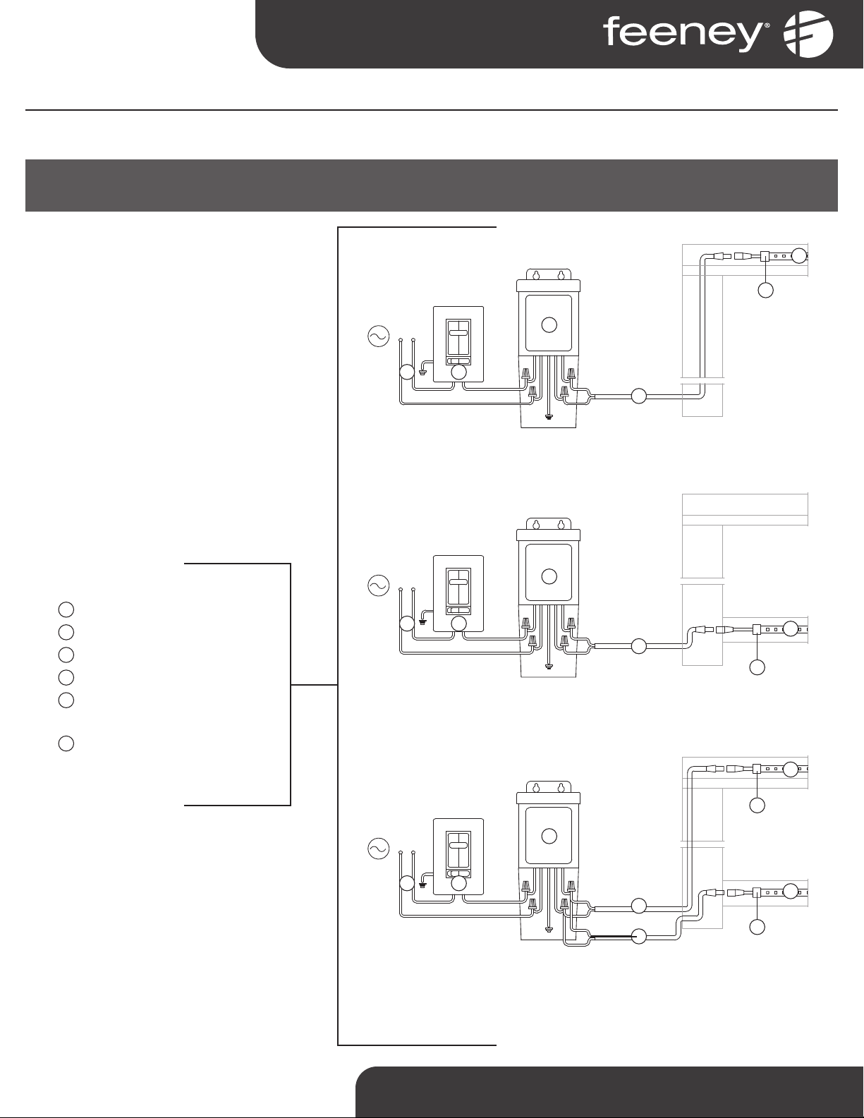
Step 1 - Install Drivers
Step 1A – Connect Source Power to Driver
IMPORTANT SAFETY NOTE: TO REDUCE RISK OF ELECTRICAL SHOCK, TURN OFF AC CIRCUIT BREAKER PRIOR TO COMMENCING ANY ELECTRICAL WORK AND
CONNECTING DRIVER(S) TO AC POWER SOURCE. VERIFY THAT LIVE POWER IS NOT PRESENT AT JUNCTION BOX WHEN MAKING CONNECTIONS.
Determine locaon of driver.
Note: It is best to locate the drivers as close as
possible to the lighࢼng to reduce the possibility
of voltage drop occuring. If possible, the driver
should be within 15 feet of the post that will
accept the 20' starter cable.
Route exterior rated wiring from compable
dimmer switch/AC power source to locaon of
driver.
Connect drivers to dimmer switch/AC power
source.
Connect 20' starter cable and route from driver
to post using supplied wire nuts.
1. Power (by customer)
2. Light Switch (by customer) 1
3. 24v Dimmable Driver 2
4. LED Starter Cable (20')
5. LED Connector Pair (Female
Connector)
6. LED Light Strip
LIGHTING COMPONENTS:
1. Mount vercally only. See Switch Compatabilty
Spec Sheet at www.feeneyinc.com
2. See Driver Spec Sheet at www.feeneyinc.com
3
4
1 2
5
6
TOP RAIL LIGHTING - WIRING DIAGRAM
BOTTOM RAIL LIGHTING - WIRING DIAGRAM
3
4
1 2
5
6
Note: If using both top and boom rail lighࢼng, run each with their own starter
cable aached to the driver.
Alternaࢼvely, a separate driver may be supplied for top and boom rail lighࢼng,
allowing for independent control of each circuit.
TOP & BOTTOM RAIL LIGHTING - WIRING DIAGRAM
3
4
1 2
5
6
5
6
4
1
2
3
4
5
6
1-800-888-2418 | www.feeneyinc.com4
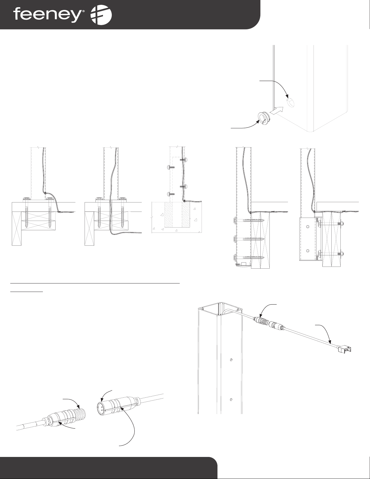
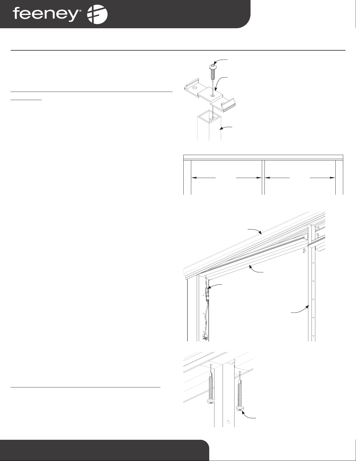
Step 1B - Drill Posts and Route Starter Cable
Determine the post that will act as the starng post, this will likely
be designated on the lighng layout schemac received with the
order. Installing the starter cable through the post is easiest when
done prior to mounng the post.
Determine the locaon that the starter cable will enter the starng
post.
Note: Depending on the post mounࢼng method, and driver locaࢼon
relaࢼve to the post, the starter cable entrance point may vary. (See
Figure 1.2 for typical recommendaࢼons)
Figure 1.1
1/2" DIA.
HOLE
GROMMET
PART #1114
For systems with lighng installed into Series 200, 300, 350, or
450 top rail:
Fish the connector for the starter cable through the post and out
of the top, and aach LED Connector (Female) to Starter Cable.
(See Figure 1.3).
IMPORTANT NOTE: Maintaining the polarity at all connec-
on points is crical. Constant alignment verificaon
of the of the posive and negave signs will guarantee
less problems and rework.
Use masking tape to temporarily secure starter cable to outside
of post to prevent retracng back into post.
WIRE COMES
UP THROUGH
DECKING AND
INTO POST.
WIRE CAN BE RUN
IN CONDUIT BURIED
IN CONCRETE, OR
RUN DIRECTLY
FROM ENCLOSURE
TO POST. WIRE
INSIDE POST RUNS
BETWEEN INSIDE
POST WALL AND
STANCHION.
WIRE RUNS UNDER
DECK THROUGH
FASCIA BOARDS
AND ENTERS POST
BELOW DECKING
SURFACE BETWEEN
FACSIA AND POST
FACE.
WIRE RUNS
UNDER DECK AND
ENTERS POST
ABOVE FASICA
BRACKET BELOW
DECKING.
WIRE RUNS UNDER
DECK THROUGH 3/4"
HOLE IN BASEPLATE
AND BLOCKING.
(3/4" HOLE DRILLED BY
CUSTOMER)
Figure 1.2
LED CONNECTOR
(FEMALE)
STARTER CABLE
Figure 1.3
MALE CONNECTOR
FEMALE CONNECTOR
Keep the straight line
on the outside maࢼng
connecࢼon aligned
1-800-888-2418 | www.feeneyinc.com 5
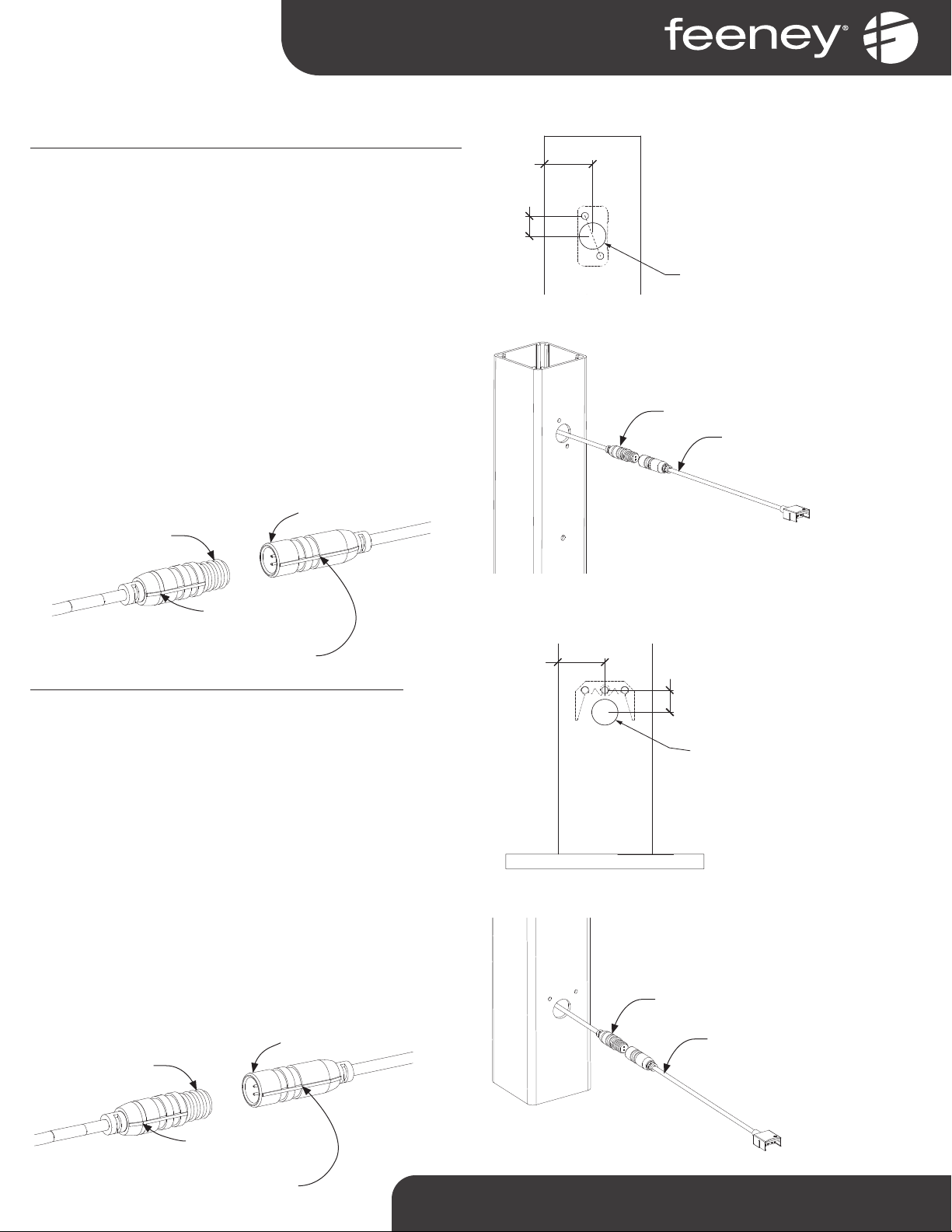
For systems with lighng installed into Series 150 top rail:
Drill an 11/16” diameter hole vercally centered between the
factory pre-drilled top rail RCB holes. This will allow the light
strip and connector to pass through the RCB hollow (See Figure
1.4). Repeat this step for each post which will have light strips
running through it. For stair posts, pre-drill top rail RCB holes as
needed, and then pre-drill 11/16" diameter hole.
Pull starter cable out through drilled hole between RCB holes,
and aach LED Connector (Female) to Starter Cable (See Figure
1.5).
IMPORTANT NOTE: Maintaining the polarity at all con-
necon points is crical. Constant alignment verifi-
caon of the of the posive and negave signs will
guarantee less problems and rework.
Use masking tape to temporarily secure starter cable to outside
of post to prevent retracng back into post.
For systems with lighng installed into Boom Rail: Drill an
11/16” dia. hole, at 9/16” below and centered between the
boom rail RCB holes (See Figure 1.6). Repeat this step for each
post which will have light strips running through it. For stair
posts, pre-drill boom rail RCB holes as needed, and then pre-
drill 11/16" diameter hole.
Pull starter cable out through drilled hole between RCB holes,
and aach LED Connector (Female) to Starter Cable (See Figure
1.7).
IMPORTANT NOTE: Maintaining the polarity at all con-
necon points is crical. Constant alignment verifi-
caon of the of the posive and negave signs will
guarantee less problems and rework.
Use masking tape to temporarily secure starter cable to outside
of post to prevent retracng back into post.
Step 1B - Connued
11/16" HOLE
1-3/16"
1/2"
TOP OF POST
Figure 1.4
1-3/16"
11/16" HOLE
9/16"
BOTTOM OF POST
Figure 1.6
Figure 1.5
LED CONNECTOR
(FEMALE)
STARTER CABLE
Figure 1.7
LED CONNECTOR
(FEMALE)
STARTER CABLE
MALE CONNECTOR
FEMALE CONNECTOR
Keep the straight line
on the outside maࢼng
connecࢼon aligned
MALE CONNECTOR
FEMALE CONNECTOR
Keep the straight line
on the outside maࢼng
connecࢼon aligned
1-800-888-2418 | www.feeneyinc.com6
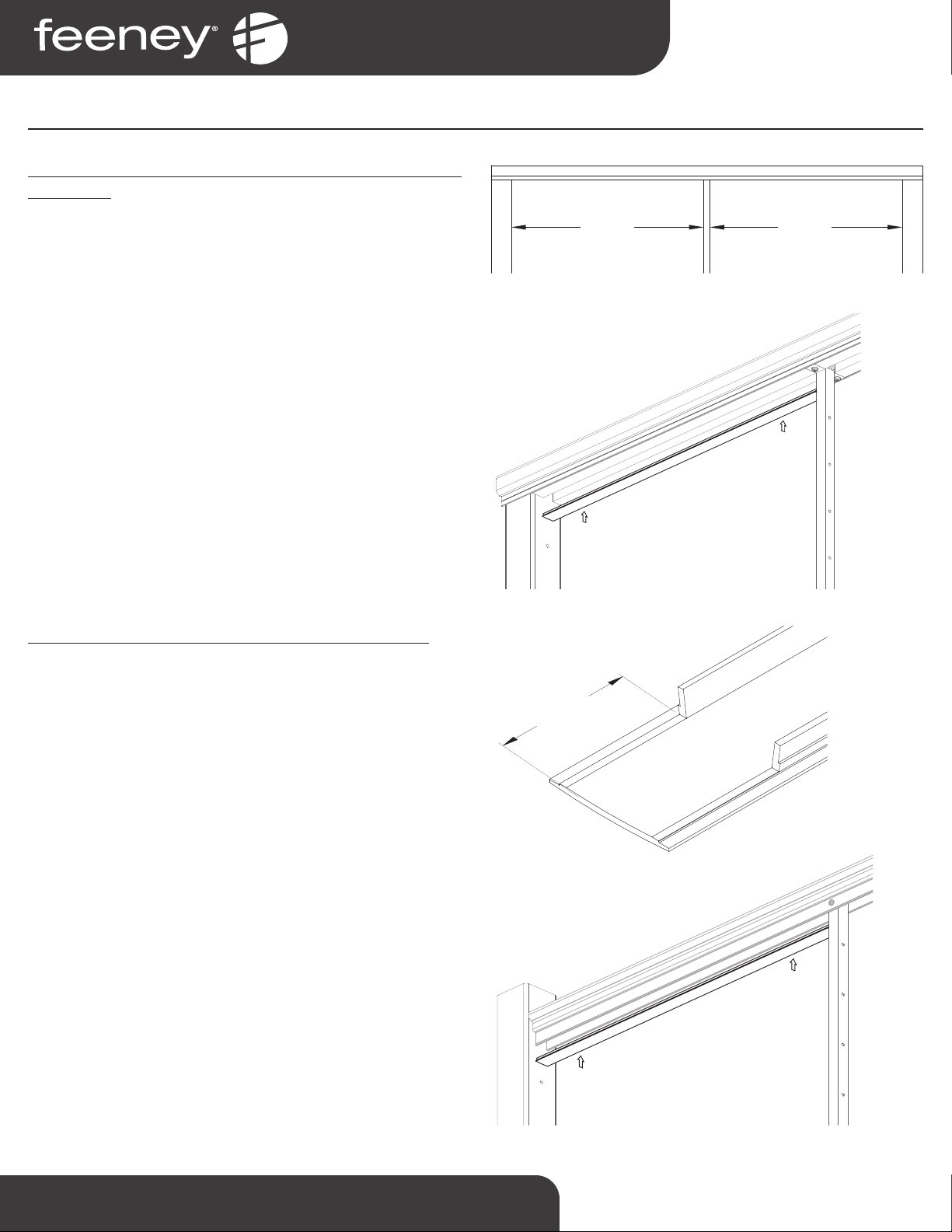
Step 2 - Prepare Railing Frame
Following driver installaon, and aer roung the starter
cable, install all posts and top rail per DesignRail Installaon
Instrucons.
For systems with lighng installed into Series 200, 300, 350, or
450 top rail:
Aach 3/4” wide piece of standard infill to top of intermediate
pickets using #10 x 3/4” screw (See Figure 2.1).
Follow standard DesignRail installaon instrucons for aaching
boom rail, or picket base plate, and install picket sub-assembly
panels.
Measure the opening between the picket and post face on each
side of the picket (See Figure 2.2). These dimensions should be
equal. Cut top rail insert for lighng, to fit on each side of the
picket.
Install top rail insert on each side of picket. Avoid pinching
starter cable by starng insert at a slight angle and rotang up
and snapping into top rail (See Figure 2.3).
Secure intermediate picket to top rail using (2x) #8 x 1” self-
tapping screws (See Figure 2.4).
For systems with lighng installed into Series 150 top rail:
Intermediate picket can be directly aached to flange of built-in
channel. Light strips will install directly into top rail, without an
addional insert
Figure 2.2
MEASURE MEASURE
Figure 2.1
#10 x 3/4"
SCREW
3/4" WIDE PIECE
OF STANDARD TOP
RAIL INFILL FOR
CABLERAIL
INTERMEDIATE
PICKET
Figure 2.3
STARTER CABLE
WITH LED CONNECTOR
TOP RAIL
INSERT FOR
LIGHTING
INTERMEDIATE
PICKET
TOP RAIL
Figure 2.4
#8 x 1" SELF-TAPPING
SCREW

1-800-888-2418 | www.feeneyinc.com 7
For systems with lighng installed into Boom Rail:
Measure opening between the post faces beneath the boom
rail (See Figure 2.5).
Cut channeled boom rail inert to fit between posts.
Trim channel poron of isert at both ends to clear RCBs. This can
be done by cung the ‘top’ of the channel to a point just above
the flanges, then ‘snipping’ the sides to remove (See Figure 2.6).
Install boom rail insert between posts (See Figure 2.7).
Figure 2.6
1-1/4"
Figure 2.7
BOTTOM RAIL
BOTTOM RAIL
INSERT
STARTER CABLE
WITH LED CONNECTOR
Figure 2.5
MEASURE
Step 2 - Connued

1-800-888-2418 | www.feeneyinc.com8
Measure length of strip light needed for run (face of post to
face of post). Reference lighng layout for approximate light
strip engths.
Cut light strip to length at nearest cut mark. Cut marks are
located approx. every 4-inches. Using scissors cut between
the 4 copper dots (See Figure 3.1).
Determine which end of light strip will be used at starng
post, by lining up the posve symbol on the light strip with
the posive symbol on the LED Connector. Be sure to
account for the back of the light strip (the side with the tape)
needing to face upwards. The light strip may need to be
flipped end for end in order to avoid twisng when properly
oriented (See Figure 3.2).
Roll back the adhesive tape at the end of the light strip just
enough so that it is out of the way of where the connector
will be placed. Use the provided silicone and affix the clear
plasc sleeve to the end of the light strip, make sure window
opening is oriented so that the copper dots are aligned in
opening (See Figure 3.3). The end of the light strip is now
ready to be snapped into the connector.
Snap the light strip onto the starter cable LED connector
assembly by firmly pressing the clear plasc sleeve into the
connector. The prongs of the LED connector will enter in
through the opening in the clear plasc sleeve and pierce
the light strip, contacng the copper dots (See Figure 3.4).
Step 3 - Install Light Strips
DC 24V DC 24V DC 24V DC 24V
Figure 3.1
LED CONNECTOR
CLEAR PLASTIC SLEEVE
LIGHT STRIP
Figure 3.2
POSITIVE
SYMBOL
LED CONNECTOR
CLEAR PLASTIC SLEEVE
LIGHT STRIP
Figure 3.4
Figure 3.3
CLEAR PLASTIC SLEEVE
LIGHT STRIP
LIGHT STRIP
ADHESIVE TAPE

1-800-888-2418 | www.feeneyinc.com 9
Peel back the adhesive tape protecve layer about 6 to
12 inches, enough to begin scking the light strip to the
underside of the channel.
Stuffstarter cable and connector back into post, so that light
strip starts as close to the face of the post as possible. Push
the light strip up and hold with firm pressure, allowing the
adhesive to bond to the aluminum (See Figure 3.5). Connue
peeling back the adhesive tape protecve layer and adhering
the light strip to the railing a few feet at a me.
For systems with lighng installed into Series 200, 300,
350, or 450 top rail:
Connue the enre light strip along the length of the top rail,
passing the light strip over the top of the posts and pickets.
For systems with lighng installed into Series 150 top rail:
Connue the enre light strip along the length of the top
rail, passing the light strip over the intermediate pickets,
through the pre-drilled holes and RCBs in the channel of the
Series 150 top rail.
For systems with lighng installed into Boom Rail:
Connue the enre light strip along the length of the boom
rail, passing the light strip through the pre-drilled holes and
RCBs in the channel of the boom rail insert (See Figure 3.6).
Corner post condions and newel post stair transions may
require addional connectors. See following details for
specific installaon condion soluons.
Figure 3.5
Figure 3.6
Step 3 - Connued

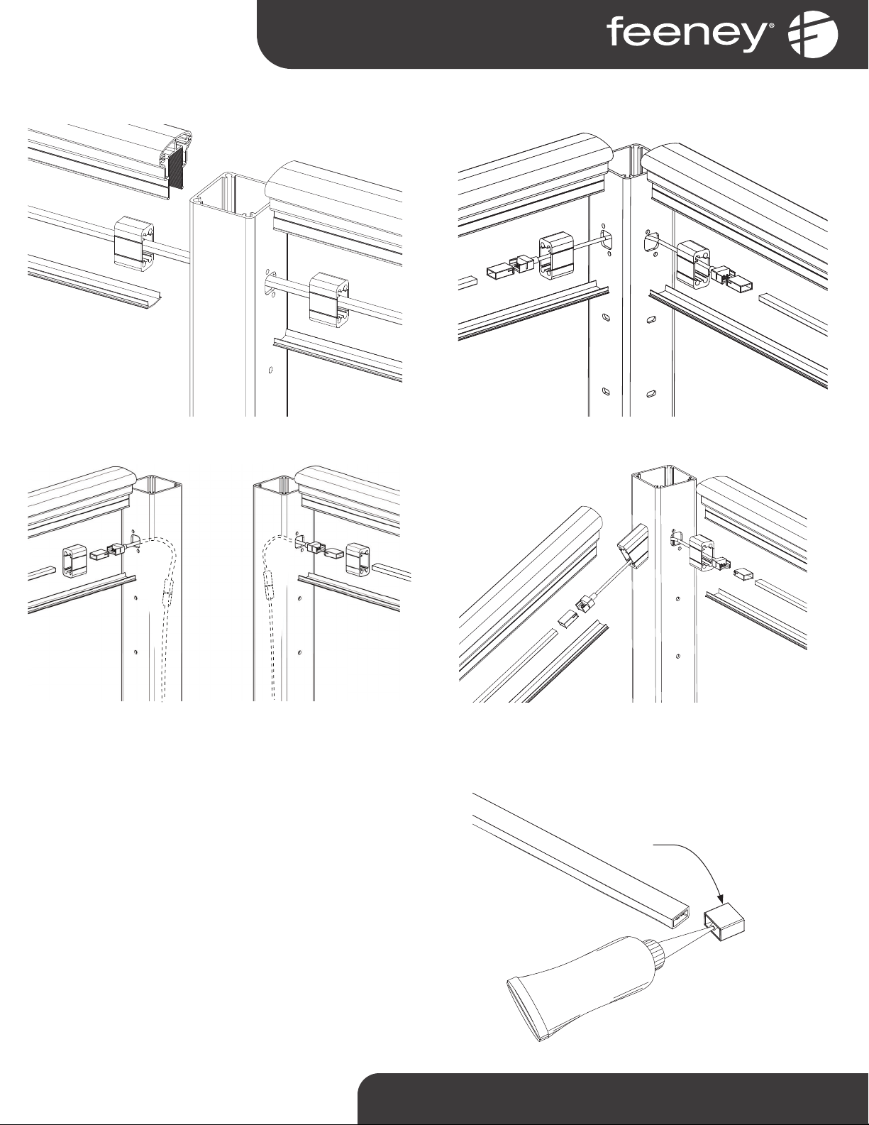
1-800-888-2418 | www.feeneyinc.com10
Intermediate Post with Series 200, 300, 350 or 450 top rail
and boom rail
Stair Newel Post with Series 200, 300, 350, 450 top rail and
boom rail on level and Series 150 and boom rail on stairs
Single Corner Post with Series 200, 300, 350, 450 top rail
and boom rail
Double Corner Post with Series 200, 300, 350, 450 top rail
and boom rail
Lighng in Series 200, 300, 350 or 450 Top Rail and Boom Rail Details
1-800-888-2418 | www.feeneyinc.com 11
Lighng in Series 150 Top Rail Details
Stair Newel Post with Series 150 top railDouble Corner Posts with Series 150 top rail
Single Corner Post with Series 150 top railIntermediate Post with series 150 top rail
At the exposed terminaon end of the light strip, where no more
connecons will be made roll back the adhesive tape. Use the
provided silicone and affix an end cap. (See Figure 3.4).
END CAP
Figure 3.4
1-800-888-2418 | www.feeneyinc.com12
For systems with lighng installed into Series 200, 300, 350, or
450 top rail:
Measure the opening between the picket and post face on each
side of the picket (See Figure 4.1). These dimensions should be
equal.
Cut diffuser lens to length to fit on each side of the picket, using
a sharp ulity knife, or heavy duty ulity scissors/shears.
Insert diffuser lens into top rail insert, or top rail flanges, as
shown. (See Figure 4.2).
For systems with lighng installed into Series 150 top rail:
Follow the same instrucons for measuring and cung diffuser
lens to length, as for other top rails (shown above).
Trim 1-1/4” of the ‘tension flanges’ at the end of the diffuser lens
that will be under the top rail RCB. Trimming is best done with
a small backsaw or sharp ulity knife. This will keep the diffuser
lens from interfering with the boom of the RCB. (See Figure 4.3).
Insert diffuser lens into top rail insert, or top rail flanges, as
shown. (See Figure 4.4)
Figure 4.1
MEASURE MEASURE
Figure 4.4
Figure 4.3
1-1/4"
Step 4 - Install Diffuser Lens
Figure 4.2

1-800-888-2418 | www.feeneyinc.com 13
For systems with lighng installed into Boom Rail:
Measure opening between the post faces beneath the boom
rail (See Figure 4.5).
Cut diffuser lens to length, using a sharp ulity knife, or heavy
duty ulity scissors/shears.
Depending on the length of the boom rail it may require more
than one piece of diffuser lens to fill the enre length. In this
case, insert the full 36” lens, then trim the second lens to fit the
remainder of the opening.
Insert diffuser lens into boom rail infill, as shown (See Figure 4.6).
MEASURE
Figure 4.5
Figure 4.6
Step 4 - Connued
LED Lighng - Troubleshoong
Scenario #1 - If all locaons do not illuminate, there could be a polarity issue
1. Turn offAC circuit breaker prior to connuing the next procedure.
2. Swap the wires at the driver terminals
3. Replace cover on driver unit
4. Turn on AC circuit breaker
5. Power up the driver and check all LED locaons for illuminaon
Scenario #2 - Some LED locaons are illuminated but others are not
1. Note which locaons are not illuminang
2. Turn offAC circuit breaker prior to connuing to next procedure
3. Rotate the connector 180 degrees at each noted locaon where the light strip is not illuminang
4. Repeat at all noted locaons that did not illuminate
5. Turn on AC circuit breaker
6. Power up the driver and check all locaons for illuminaon
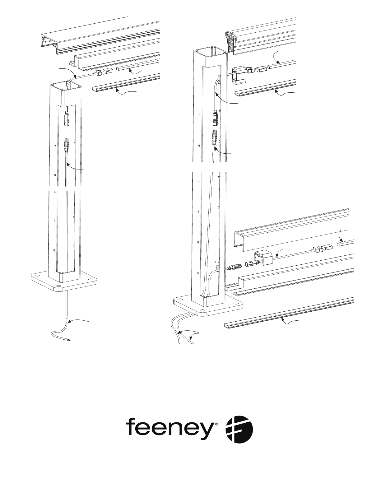
Starng Post with Top Rail Lighng, shown
with series 450 top rail (Series 200, 300, and
350 top rail similar)
Light Strip
Starter Cable (20')
LED Connector (Female)
Diffuser Lens
Top Rail
Bottom Rail
Starter Cable
Diffuser Lens
Light Strip
Bottom Rail Insert
LED Connector Pair
(Female)
Top Rail
Top Rail Insert
LED Connector
(Female)
Diffuser Lens
Starter Cable (20')
Starter Cable
Light Strip
www.feeneyinc.com
1-800-888-2418
©2021 Feeney, Inc. (09/21)
EXPLODED ISOMETRIC VIEWS
Starng Post with Top Rail and Boom Rail
Lighng, shown with series 150 top rail
Table of contents
Popular Lighting Equipment manuals by other brands


JONATHAN Y
JONATHAN Y JYL3050 instructions

Williams-Sonoma
Williams-Sonoma Hayes Assembly instructions

National Specialty Lighting
National Specialty Lighting LED Brick Star Gen I installation instructions

Lightmaxx
Lightmaxx VEGA DOT 60 user manual

Clas Ohlson
Clas Ohlson SCSYD001 quick start guide

Generac Power Systems
Generac Power Systems CTF 10mt owner's manual

Mania
Mania ILLUSIOLIGHT instruction manual

VisionAid
VisionAid StandBright 2 instructions

ADJ
ADJ INNO POCKET Z4 User instructions

Capital Play
Capital Play Trampoline MagicNight Lights Installation Manual & Safety Instructions

Cooper Crouse-Hinds
Cooper Crouse-Hinds 858 Series instruction manual

Terex
Terex Series AL4000 Operator's manual