Felicitysolar SCHM Series User manual

USER GUIDE
MPPT Controller SCHM Series User Guide
MPPT solar charge controller
Make life full of hope
358-010003-04358-010155-00

1 ABOUT THIS MANUAL ..................................................................................... 1
1.1 Purpose ................................................................................................. 1
1.2 Scope .................................................................................................... 1
1.3 SAFETY INSTRUCTIONS ........................................................................ 1
2 INTRODUCTION .............................................................................................. 2
2.1 Features................................................................................................. 2
2.2 Product Overview ................................................................................... 2
3. INSTALLATION ............................................................................................... 3
3.1 Unpacking and Inspection ........................................................................ 3
3.2 Preparation ............................................................................................ 3
3.3 Mounting the Unit .................................................................................... 3
3.4 Power Connection ................................................................................... 4
4. OPERATION ................................................................................................... 6
4.1 Power-Up ............................................................................................... 6
4.2 Operation and Display Panel .................................................................... 6
4.3 LCD Display Icons ................................................................................... 7
4.4 LCD setting ............................................................................................. 8
4.5 Reference Code ...................................................................................... 11
5. CHARGING LOGIC ......................................................................................... 12
5.1 3-stage Charging .................................................................................... 12
5.2 Setting Parameter and Default Value ........................................................ 13
6. TROUBLE SHOOTING .................................................................................... 14
7. SPECIFICATIONS ........................................................................................... 15
Contents
3.5 Grounding and Ground Fault Interruption................................................... 4
6 7 8 9
4
5
1
23
01 02
•Intelligent Maximum Power Point Tracking technology increases efficiency 25%~30%
•Compatible for PV systems in 96V~ 384V(from 8 packs to 32 packs)
•Three-stage charging optimizes battery performance (Two-stage charging in lithium battery mode)
•Maximum charging current up to 25/ 50A
•Maximum efficiency up to 98%
•Supports lithium battery and various lead-acid batteries, AGM and gel battery
•Integrated intelligent slot compatible with MODBUS communication
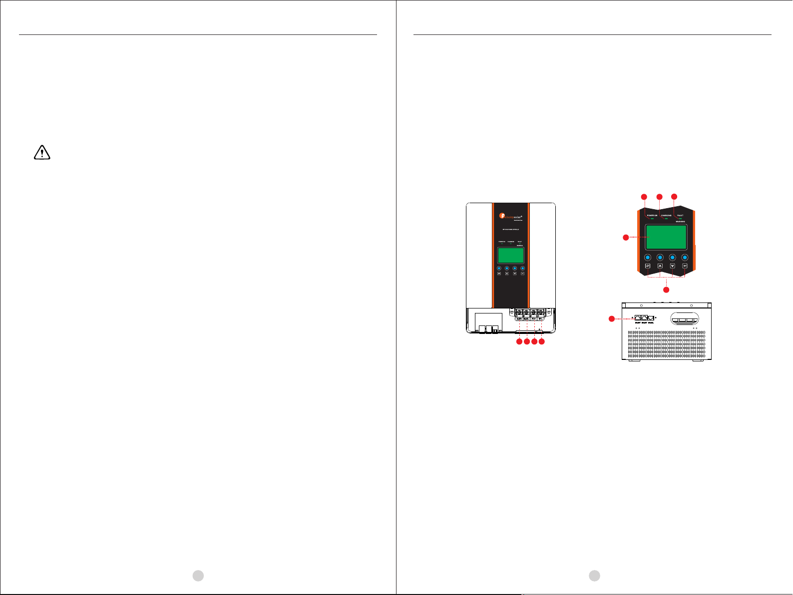
2.2 Product Overview
2.1 Features
MPPT solar charge controller MPPT solar charge controller
1. LCD display 2. Power On indicator 3. Charging indicator
4. Fault and warning indicator 5. Operation button 6. Battery Positive +
7. Battery Negative - 8.PV Positive + 9. PV Negative -
10. Communication Port
10
2. INTRODUCTION
1.1 Purpose
This manual describes the assembly, installation, operation and troubleshooting of this unit. Please read
this manual carefully before installations and operations. Keep this manual for future reference.
1.2 Scope
This manual provides safety and installation guidelines as well as information on tools and wiring.
1.3 SAFETY INSTRUCTIONS
WARNING: This chapter contains important safety and operating instructions. Read and keep
this manual for future reference.
1. Before using the unit, read all instructions and cautionary markings on the unit, the batteries and all
appropriate sections of this manual.
2. Do not disassemble the unit. Take it to a qualified service center when service or repair is required.
Incorrect re-assembly may result in a risk of electric shock or fire.
3. To reduce risk of electric shock, disconnect all wirings before attempting any maintenance or cleaning.
Turning off the unit will not reduce this risk.
4. CAUTION – Only qualified personnel can install this device with battery.
5. NEVER charge a frozen battery.
6. For optimum operation of this charger, please follow required spec to select appropriate cable size. It’s
very important to correctly operate this charger.
7. Be very cautious when working with metal tools on or around batteries. A potential risk exists to drop a
tool to spark or short circuit batteries or other electrical parts and could cause an explosion.
8. Please strictly follow installation procedure when you want to disconnect PV or battery terminals. Please
refer to Installation section of this manual for the details.
9. GROUNDING INSTRUCTIONS -This charger should be connected to a permanent grounded wiring
system. Be sure to comply with local requirements and regulation to install this charger.
10. NEVER cause short circuited on battery output.
11. Warning!! Only qualified service persons are able to service this device. If errors still persist after following
troubleshooting table, please send this charger back to local dealer or service center for maintenance.
1 ABOUT THIS MANUAL
Thank you for selecting this solar charge controller. This solar charge controller is an advanced solar
charger with maximum power point tracking. Applying intelligent MPPT algorithm, it allows solar charge
controller to extract maximum power from solar arrays by finding the maximum power point of the array.
The MPPT battery charging process has been optimized for long battery life and improved system performance.
Self-diagnostics and electronic error protections prevent damage when installation errors or system faults
occur. The charger also has a multi-functional LCD and communication port to monitor controller status.

1
03 04
Install the unit to the wall by screwing two screws.
Refer to right chart.
Overcurrent Protection and Disconnects
Recommended breaker rating:
Minimum battery circuit breaker/fuse rating
1.25 x 25Amps = 31.3 Amps 1.25 x 50Amps = 62.5 Amps
A disconnect is required for the battery and solar circuits to provide a means for removing power from
the charger. Double pole switches or breakers are convenient for disconnecting both solar and battery
conductors simultaneously.
Connect the Power Wires
The solar modules can produce open-circuit voltages in excess of 100 Vdc when in sunlight. Verify if solar
input breaker or disconnect has been opened (disconnected)before connecting system wires.
WARNING: Shock Hazard
3. INSTALLATION
3.2 Preparation
Before installation, please inspect the unit. Be sure that nothing inside the package is
damaged. You should have received the following items inside of package:
•Solar charge controller x 1
•User manual x 1
Before connecting all wirings, please take off wiring box cover by removing screws as
shown below.
3.1 Unpacking and Inspection
3.4 Power Connection
The table below provides the recommended minimum wire size allowed for the charger.
Wire types rated for 75°C and 90°C are listed.
Minimum Wire Size
Wire size
Recommended wire size:
MPPT solar charge controller MPPT solar charge controller
Typical Amperage Wire Type 75° °C Wire 90° °C Wire
Copper 4 AWG (25 m㎡ ) 6 AWG (16 m㎡ )
Aluminum 2 AWG (35 m㎡ ) 4 AWG (25 m㎡)
50A
Copper 8 AWG (10 m㎡ ) 8 AWG (10 m㎡ )
Aluminum 6 AWG (16 m㎡ ) 6 AWG (16 m㎡)
25A
3.3 Mounting the Unit
50CM50CM
20CM 20CM
PV+ PV-
BATTERY+
BATTERY-
Consider the following points before selecting where to install:
• This solar charge controller is designed in IP20 for indoor applications only.
• Do not mount the unit on flammable construction materials.
• Mount on a solid surface
• Install this charger at eye level in order to allow the LCD display
to be read at all times.
• For proper air circulation to dissipate heat, allow a
clearance of approx. 20 cm to the side and approx. 50 cm
above and below the unit.
• The ambient temperature should be between 0°C and 55°C
to ensure optimal operation.
• The recommended installation position is to be adhered to
the wall vertically.
The four large power terminals are sized for 14 - 2 AWG (2.5 - 35mm 2 ) wire. The terminals are rated for
copper and aluminum conductors. Use UL-listed Class B 600Volt stranded wire for SCHM50240 model/
1000Volt stranded wire for SCHM25384 model. Good system design generally requires large conductor
wires for solar module and battery connections that limit voltage drop losses to 2% or less.
CAUTION: Circuit breakers or fuses must be installed in both battery and solar circuits.
The battery circuit breaker or fuse must be rated to 125% of the maximum current or more. The recommended
breaker/fuse rating for use with the charger is listed in the below table.
NO NAME SPECIFICATION PICTURE
Screw Mounting screw
User manual User manual
Guarantee card Guarantee card
1
2
33
2
23
•Screw x n
•Guarantee card x 1

05 06
WARNING: Risk of Damage
Be sure that the battery connection is made with correct polarity. Turn on the battery breaker/disconnect
and measure the voltage on the open battery wires BEFORE connecting to the controller. Disconnect the
battery breaker/disconnect before wiring to the controller.
4. Connect positive terminal (+) of battery to the battery positive terminal (+) on the controller.
5. Connect negative terminal (-) of battery to the battery negative terminal (-) on the controller.
WARNING: Risk of Damage
Be sure that solar connection is made with correct polarity. Turn on the solar breaker/disconnect and measure
the voltage on the open wires BEFORE connecting to the controller. Disconnect solar breaker/disconnect
before wiring to the controller.
6. Connect positive wire (+) of solar module to the PV positive terminal (+) on the controller.
7. Connect negative wire (-) of solar module to the PV negative terminal (-) on the controller.
8. Screw four (4) power terminals tightly with 50 in-lbs torque. (5.65 Nm)
MPPT solar charge controller MPPT solar charge controller
4. OPERATION
Connecting the solar module to the battery connector will permanently damage the controller.
• Confirm that the solar and battery polarities are correctly connected to the controller.
• A battery must be connected to the controller before operating it. The controller will not operate only with
solar input. Solar input can trigger the controller to start up when the battery is connected without pressing
the button.
• Turn on battery disconnect switch first, and then turn on solar disconnect switch. If the solar module is
in full sunlight, the controller will begin charging.
• The number of battery must be seted according to actual needs in the first uesd (in seting program 05).
Otherwise, the controller can’t work properly and 25 warning occur.
4.1 Power-Up
WARNING: Risk of Damage
4.2 Operation and Display Panel
The operation and display panel, shown in below chart, is on the front p ane l of t he c ontroller. It includes
three indicators, four operation buttons and a LCD display, indicating the operating status and input/output
power information.
LED Indicator
LED Indicator Messages
POWER ON Green
Solid On
Light off
WARNING/FAULT
CHARGING Green
Red
Flashing
Solid On
PV Voltage is fault
The controller is charging.
Bulk charge stage: flashing every 0.5 second
Absorption stage: flashing every 0.5 second
Lithium battery wake-up: flashing every 0.3 seconds
Fault status
PV Voltage is OK
Solid On Float stage
Flashing Warning status: flashing every 0.5 second
3.5 Grounding and Ground Fault Interruption
Use a copper wire to connect the grounding terminal in the wiring box to earth ground.The grounding terminal
is identified by the ground symbol shown below that is stamped into the outside box on the right side of the
terminal block:
The minimum size of the copper grounding wire is 8 AWG (10 mm2).
WARNING: Risk of Fire
DO NOT bond system electrical negative to earth ground at the controller.
Connect terminals by following below steps (Refer to diagram above):
1. Make sure that the system input and output disconnect switches are both turned off before connecting
power wires to the charger. There are no disconnecting switches inside the charger.
2. Make 4 power wires first. M6 wiring terminal is selected.
Refer to the chart below.
3. Pull all wires into the wiring box.
M6

07 08
MPPT solar charge controller MPPT solar charge controller
Button Operation
4.3 LCD Display Icons
Icon Function description
Indicates the PV input voltage, BAT charging voltage ,BAT charging current.
Indicates battery level by 0-20%, 21-40%, 41-60%, 61-80% and 81-100% in charging
status.
Disapper
Indicates charging dynamics .
Indicates PV voltage
To go to next selection
BATTYPE
CHGLIMIT
Indicates warning/fault codes.
Indicates battery voltage
Battery Charging Status
Constant
Current
mode /
Constant
Voltage
mode
< 2V/cell Five bars will flash in turns.
2 ~ 2.055V/cell The down bar will be on and the other four bars
will flash in turns.
2.055 ~ 2.11V/cell The two down bars will be on and the other three
bars will flash in turns.
The four down bars will be on and the less bar will
flash.
Batteries are fully charged. 5 bars will be on.
Floating mode
Status Battery voltage LCD Display
4.4 LCD setting
Setting Programs:
0 0
Program Description Options
Exit setting mode
Escape
Maximum charging current
0 1
50A(Default for
SCHM50240 model)
Short press "ENTER" button to enter
the seting status, after that, shortly
press "UP"or "DOWN" button to
increase or decrease 1A each time,
and after pressing "UP"or "DOWN"
button for 2.5 seconds, it will increase
or decrease 10A every 0.5 seconds.
> 2.167 V/cell
The three down bars will be on and the other two
bars will flash in turns.
2.11 ~2.167V/cell
Indicates battery current
Indicates software version
25A(Default for
SCHM25384 model)
Input/Output Information
Flashing
Solid on
PV voltage is too low
PV voltage is too hight
PV voltage is ok
Flashing indicates battery disconnect

09 10
MPPT solar charge controller MPPT solar charge controller
Battery type
0 2
Absorption voltage
0 3
0 4 Float voltage
If “Use-Defined” is selected in
program 02, this program can be set
up. The setting range is from 12.0V
to 15.0V. If “LIb” is selected in
program 02, this parameter is
consistent with absorption voltage.
Use-Defined(Default)
14.4V (Default)
Press "UP" or "DOWN" button to
modify, increment of each short press
is 0.1V, and after pressing for 2.5
seconds, it will charge 1V every 0.5
seconds. Once the value is achieved
15.0V, the value will jump back to12.0V.
13.6V (Default)
Press "UP" or "DOWN" button to
modify, increment of each short press
is 0.1V, and after pressing for 2.5
seconds, it will charge 1V every 0.5
seconds. Once the value is achieved
15.0V, the value will jump back to 12.0V.
AGM
LIB
0 6 Battery C.V. charging
duration
2.5 hours(Default)
0 5 Number of battery
0 7 Back light of LCD
ENA(Default)
Setting the control of LCD backlight
enable, LCD backlight will always-on.
Setting the control of LCD backlight
disable, have no operation the LCD
backlight will go out after 60s.
For SCHM50240 model
For SCHM25384 model
0 8 Battery charging
enable
ENA(Default)
ENA: Charging enable
DIS: Charging disable
If “Use-Defined” or “Lib” is selected
in program 02, this program can be
set up. The setting range is from
12.0V to 15.0V.
This program and program 05
constitute the total charging voltage.
For example, the absorption voltage is
14.4V, the setting value of program 05
is 20, and the total charging voltage
is 288V =14.4V X20.
This program and program 05
constitute the total float voltage.
For example, the float voltage is 13.6V,
the setting value of program 05 is 20,
and the total charging voltage
is 272V =13.6V X20.
If “Use-Defined” is selected, battery
charge voltage can be set up in
program 03 and 04 . If “Lib” is selected,
battery charge voltage can be set up in
program 03 .
Note:Program 03,04 and 05 is
designed for lead acid batteries, AGM
batteries and gel batteries. If lithium
batteries are used, ensure that the total
charging voltage set by the controller is
not greater than the rated charging
voltage of lithium batteries.
The setting range is from 0.1 hours to
15 hours. Press "UP"or"DOWN" button
to modify, increment of each short press
is 0.1 hours, and after pressing
for 2.5 seconds, lt wil charge 1 hours
every 0.5 seconds. It will jump back to
0.1hours after 15 is achieved.
Set the number of batteries in series
according to actual use.The 50240
model setting range is from 8 packs to
20 packs (96V~240V) and the 25384
model setting range is from 20 packs to
32 packs (240V~384V).
Note 1:One pack corresponds to 12V.
Note 2:This program applies to lead
acid batteries, AGM batteries and gel
batteries.
If 'Lib' is set in program 02, This
program should be set according to the
charging voltage of lithium battery and
make sure the controller total charging
voltage does not exceed the charging
voltage of the lithium battery. For the
calculation method of the total charging
voltage of the controller, refer to
program 03.

4.5 Reference Code
Type Code Event
Warning
20
Output derating caused from high PV voltage
Output derating caused from high temperature
Fan1 failure
Fan2 failure
Fan3 failure
21
22
23
24
25
11 12
MPPT solar charge controller MPPT solar charge controller
In general, this solar charge controller is designed with 3-stage battery charging algorithm for fast, efficient,
and safe battery charging. The following picture shows the sequence of charging stages.
5. CHARGING LOGIC
5.1 3-stage Charging
NIGHT
BULK
CHARGE
ABSORPTION FLOAT NIGHT
VOLTAGE
TIME
CURRENT
TIME
1) Bulk charge stage
In bulk charge stage, charge current begins to flow, typically at the maximum rate of the charge source. The
controller will supply solar power to charge battery as much as possible.
2) Absorption stage
When battery charging voltage is reached to Absorption voltage point, the charging stage changes from bulk
charge to absorption. Constant-voltage regulation is used to maintain battery voltage at the absorption stage.
If the charging current drops to one-tenth of the maximum charging current setting point, the charging status
will change to float stage.
Voltage
Current
FLOAT
One-tenth of Max.
charging current set point
ABSORPTION
Absorption
Voltage
FLOAT
BULK
ABSORPTION
C.V. Charging
Time
If the elapsed time of absorption stage is over
setting value for C-V charging time, it
will also transfer to float stage.
3) Float Stage
After the battery is fully charged in the absorption stage,
the controller will reduces the battery voltage to the
setting point of float voltage. Once in float stage,
constant-voltage regulation is used to maintain battery
voltage at setting point of float voltage.
In lithium battery mode: the charging logic has no
floating charge stage
ABSORPTION
BULK FLOAT BULK ABSORPTION
Lower than
float voltage
for 30 min.
Float
Voltage
ABSORPTION
BULK FLOAT BULK ABSORPTION
Float Voltage
FLOAT Cancel
Voltage
Float timeout
If the battery voltage remains lower than the float
voltage for 30minutes, the controller will return to bulk
charging stage.
Once the battery voltage drops to setting point of
float cancel voltage, the controller also returns to
bulk charging stage. Float cancel voltage = floating
charging voltage – (1V x battery numbers in series)
Float cancel voltage
( No floating charge
in lithium battery mode )
IIC-eeprom fault
11
Battery voltage is too high
06
Battery current senser fault
08
Battery voltage senser fault
09
Heatsink1 temperature-variable fault
04
Heatsink2 temperature-variable fault
05
Over temperature fault
03
Software detect over current fault
01
Hardware detect over current fault
02
FAULT
NTC disconnect
12
PV is high loss
10
Battery short
07
Software version and hardware version do not match
13
Need to set the number of batteries in program 05 based on the actual
number of batteries

13 14
MPPT solar charge controller MPPT solar charge controller
6. TROUBLE SHOOTING
5.2 Setting Parameter and Default Value
Recommended and default parameter settings are listed below.
Battery
type
Absorp.
Stage
Float
Stage
Absorp.
Time
Parameter
Unit - Volt Volt
Option AGM 14.4 13.6
Option Flooded 14.6 13.8
Default Customized - -
Option LIb - -
hours
2.5
2.5
2.5
-
Situation
Fault Event
Fault
Code Situation
Battery voltage is too high
06
1.Check whether the rated output voltage of the battery
is correct(Program 05), and then restart the controller .
If the problem remains, please contact your installer.
Heatsink1 temperature-variable fault
04
1. Check whether the fans is turning, and whether the air
inlet and outlet is blocked.
2. Restart the controller.
3. If the problem remains, please contact your installer.
Over temperature fault
03 1. Keep the controller in the cool environment.
2. If the problem remains, please contact your installer.
Heatsink2 temperature-variable fault
05
1. Check whether the fans is turning, and whether the air
inlet and outlet is blocked.
2. Restart the controller.
3. If the problem remains, please contact your installer.
Software detect over current fault
01 1. Restart the controller.
2. If the problem remains, please contact your installer.
Hardware detect over current fault 1. Restart the controller.
2. If the problem remains, please contact your installer.
02
1. Restart the controller.
2. If the problem remains, please contact your installer.
IIC-eeprom failure
11
NTC disconnect
12 1. Restart the controller.
2. If the problem remains, please contact your installer.
PV is high loss
10
1. Verify that the pv array is correctly configured and
that the PV open-circuit voltage is within the
specifications of the controller.
2. If the problem remains, please contact your installer.
Battery current senser fault
08 1. Restart the controller.
2. If the problem remains, please contact your installer
Battery voltage senser fault
09 1. Restart the controller.
2. If the problem remains, please contact your installer.
Battery short
07
1.Check the battery terminal and the output terminal of
the controller to ensure that there is no short circuit,
and then restart the controller.
2. If the problem remains, please contact your installer.
Software version and hardware
version do not match
13 1. Restart the controller.
2. If the problem remains, please contact your installer.

15 16
MPPT solar charge controller MPPT solar charge controller
Charging curve
Bul k
(Co nst ant Cu rre nt)
Abs orp tio n
(Co nst ant Vol tag e)
Mai nte nan ce
(Fl oat ing )
100 %
50%
Time
T0 T1
T1=10*T0, minlmum 10mlns,maximum ghrs
Cur ren t
Volt age
Cha rgi ng Cur ren t,%
Bat ter y Volta ge, p er cel l
Table 3 Mechanical and Environment
Model
Ambient
Temperature
Range
Storage
Temperature
Humidity
Enclosure
0℃ to +55℃
- 40℃ to 75℃
0%-90%RH(No condensing)
IP20(indoor&vented)
Table 2 Battery Charging
Charging algorithm
Charging stages
3-Step
Bulk, Absorption, Float
Temperature
compensation
coefficient
Temperature
compensation range
MODEL
-5 mV / °C / cell (25 °C ref.)
0 °C to +50 °C
Product Size
(W x H x D,mm)
Product
Weight (Kg)
SCHM50240 SCHM25384
SCHM50240 SCHM25384
365*250*164MM
11.5KG
PV Array voltage
& Battery current
NTC(inner)
temperature &
Battery current
Protections
Solar high voltage disconnect
Solar high voltage reconnect
Battery high voltage disconnect
Battery high voltage reconnect
High temperature disconnect
High temperature reconnect
7. SPECIFICATIONS
Table 1 Electrical Specifications
Maximum Solar
Input Voltage
Maximum Input
Power
MODEL
Maximum Battery
Current
Nominal System
Voltage
500V
PV Start-up
Voltage
100V
750 850
Arr ay Vol tag e(Volts)
Bat tery Curre nt( Amps)
Maximum
Battery
Current
For SCHM25384
450 500
Arr ay Vol tag e(Volts)
Bat tery Curre nt( Amps)
Maximum
Battery
Current
For SCHM50240
30 35 40 45 50 55 60 70 75
NTC (in ner) Tempe rat ure
(de gre es C)
Bat ter y Cur rent( Amp s)
Maximum
Battery
Current
SCHM50240
50Amps
96~240V
850V
SCHM25384
25Amps
240~384V
230V
10000W
Vstart-pv
Vbat+30V Vbat+30V
Vbat+10V Vbat+10V
Vlow-pv
This manual suits for next models
2
Table of contents
Other Felicitysolar Inverter manuals

Popular Inverter manuals by other brands

Sofar solar
Sofar solar HYD 3K-EP user manual

Delta
Delta SOLIVIA 5.0 AP G3 Operation and installation manual

Tripp Lite
Tripp Lite PowerVerter PVINT375 Specification sheet

Lamarche
Lamarche LTI2 PRO Installation and operation manual

i-MO
i-MO JAGUAR CUB CM Series manual

FRONIUS
FRONIUS Eco 15.0-3-208 US installation instructions


