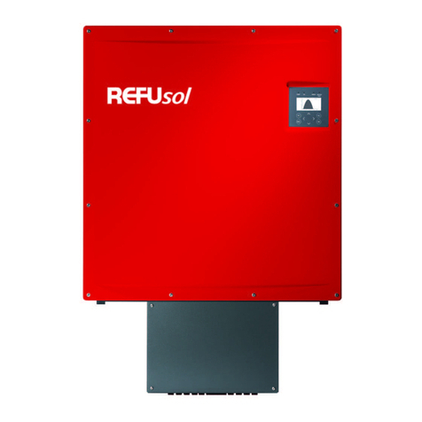
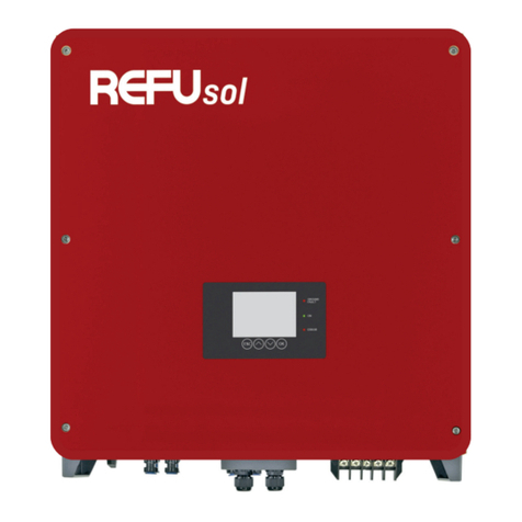
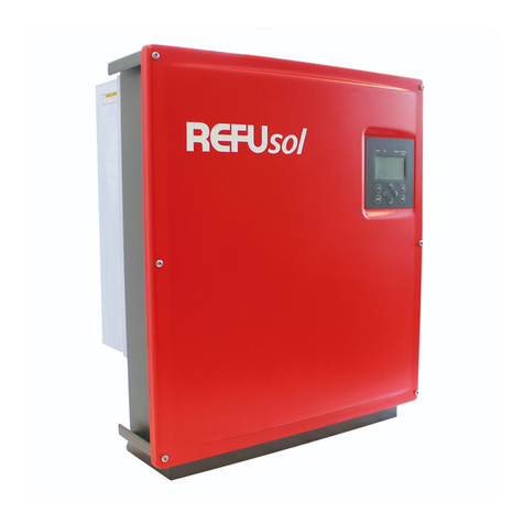
Refu sol 008K bis 20K User manual

BA_REFUSOL 008K-020K_V08.1_EN
Copyright REFUsol GmbH 1-1
REFUsol
®
– solar inverter
REFUsol®008K bis 20K
Operating instructions
Version 08.1

BA_REFUSOL 008K-020K_V08.1_EN
2 Copyright REFUsol GmbH
Title REFUsol®– Solar Inverters
Type of Documentation Operating Instructions
Published by
REFUsol GmbH
Uracher Straße 91 D-72555 Metzingen
Telephone: +49 (0) 7123 969-102 Fax +49 (0) 7123 969-333
www.refusol.com
Legal Disclaimer
All details in this documentation have been compiled and checked with
utmost care. Despite of this, faults or deviations based on technical progress
cannot be completely excluded. We therefore do not accept any liability for
their correctness.
The relevant up-to-date version can be obtained from www.refusol.com .
Copyright
The details of this documentation are the property of REFUsol GmbH.
Using and publicising this documentation, even if only in parts require
the written consent of REFUsol GmbH.
Trade Mark REFUsol®is a registered trademark of REFUsol GmbH
Marking Date of Issue Remarks
BA_REFUSOL 008K_020K_V08.1_EN 2012-10-11 MR

BA_REFUSOL 008K-020K_V08.1_EN
Copyright REFUsol GmbH 3
Table of Contents
10BRegarding these operating instructions.................................................................................. 6
1.1 Symbols and Markup ...................................................................................................... 6
1.2 Warning notices .............................................................................................................. 6
1.2.1 Lay-out of a warning notice............................................................................................. 6
1.2.2 Categories of warning notices ........................................................................................ 6
1.3 Notices ............................................................................................................................ 7
2Safety notices............................................................................................................................. 8
2.1 Proper usage .................................................................................................................. 8
2.2 Qualification of personnel ............................................................................................... 8
2.3 Dangers arising from misuse .......................................................................................... 8
2.4 Protection against touching electrical parts .................................................................... 9
2.5 Protection against magnetic & electro-magnetic fields during operation & assembly.. 10
2.6 Protection against touching hot parts ........................................................................... 10
2.7 Protection during handling and assembly..................................................................... 11
2.8 Note before starting up ................................................................................................. 11
2.9 Disposal ........................................................................................................................12
3Description of REFUsol® 008K to 020K.................................................................................. 13
3.1 Description of the Device.............................................................................................. 13
3.2 Scope of Delivery of the REFUsol®008K to 020K ....................................................... 14
3.3 Outside Dimensions of the REFUsol®008K to 020K ................................................... 14
3.4 Block Diagram of the REFUsol®008K to 020K ............................................................ 15
3.5 Solar Inverter DC Connector ........................................................................................ 15
3.6 Reverse Current through Defective Modules ............................................................... 17
3.7 Control Panel ................................................................................................................ 18
3.8 Internal Data Logger ..................................................................................................... 18
4Installation ................................................................................................................................ 19
4.1 Unpacking the Device................................................................................................... 19
4.2 Assembly Site Requirements........................................................................................ 19
4.3 Transport.......................................................................................................................21
4.4 Storage .........................................................................................................................21
4.5 Mounting the REFUsol®008K to 020K ......................................................................... 21
4.6 Connectors on the Device ............................................................................................ 23
4.7 Power Connection......................................................................................................... 23
4.8 Power Supply Line........................................................................................................ 24
4.9 Grid line inductance ...................................................................................................... 25
4.10 Grounding ..................................................................................................................... 26
4.11 Residual Current Protective Device.............................................................................. 26
4.12 PV- Generator DC Connection ..................................................................................... 27

BA_REFUSOL 008K-020K_V08.1_EN
4 Copyright REFUsol GmbH
4.13 DC Connecting Line...................................................................................................... 27
4.14 Interface Port RS485 .................................................................................................... 28
5Commissioning ........................................................................................................................ 30
5.1 Turn on the Device........................................................................................................ 30
5.2 Setting the Country Code and the Menu Language ..................................................... 31
5.3 Activating the Device .................................................................................................... 33
5.4 Navigation on the Control Panel ................................................................................... 35
5.5 Password Entry............................................................................................................. 36
5.6 Menu Structure ............................................................................................................. 39
5.7 ENS Test....................................................................................................................... 46
6Configuration ........................................................................................................................... 48
6.1 Reduction of the power output...................................................................................... 48
6.2 Communication via Ethernet......................................................................................... 48
6.3 Communication via RS485 ........................................................................................... 48
6.4 Portal monitoring........................................................................................................... 49
6.5 Sending Config ............................................................................................................. 49
6.6 Server IP .......................................................................................................................49
6.7 Server port .................................................................................................................... 49
6.8 Portal test function ........................................................................................................ 49
7Troubleshooting....................................................................................................................... 50
7.1 Self-test Error Messages .............................................................................................. 50
7.2 Transient Failure........................................................................................................... 50
7.3 Faults ............................................................................................................................ 50
7.4 Fault Acknowledgement ............................................................................................... 50
7.5 List of Fault Messages.................................................................................................. 51
8Options ..................................................................................................................................... 56
8.1 Power Plug.................................................................................................................... 56
8.2 Radiation and temperature Sensor............................................................................... 56
8.3 Remote Monitoring System .......................................................................................... 57
8.4 Instrument settings for monitoring with SolarLog®or MetoControl®............................. 58
8.5 Data Logger Parameters .............................................................................................. 59
8.6 Power Cap .................................................................................................................... 60
8.7 Connecting the AC-Adaptor Electrically to the Additional Power Cap.......................... 62
9Maintenance ............................................................................................................................. 63
10 Technical Data.......................................................................................................................... 64
10.1 Inverters ........................................................................................................................ 64
10.2 Radiation and temperature sensor ............................................................................... 66
10.3 Power Cap .................................................................................................................... 67

BA_REFUSOL 008K-020K_V08.1_EN
Copyright REFUsol GmbH 5
11 Contact...................................................................................................................................... 68
12 Certificates ............................................................................................................................... 69
13 Notes ......................................................................................................................................... 70

BA_REFUSOL 008K-020K_V08.1_EN
6 Copyright REFUsol GmbH
1 0BRegarding these operating instructions
The operating instructions form a part of the product
Read the operating instructions before using the product.
Keep the operating instructions readily available with the device for the entire life expec-
tancy of the product.
Provide access to the operating instructions to all future users of the device.
1.1 Symbols and Markup
Pre-condition
One-step operating instruction
1. Multiple-step operating instruction
Bulleted list
Highlighting Highlighting within a text
Result
1.2 Warning notices
1.2.1 Lay-out of a warning notice
WARNING
TEXT
The type and source of danger are described here.
Measures for avoiding the danger are shown here.
Example
DANGER
Death or severe injury to persons due to high discharge current when
opening the device.
It is essential to ensure an earthing connection has been established
prior to connection to the supply current circuit.
1.2.2 Categories of warning notices
There are three categories of warning notices
DANGER
"DANGER" designates a safety notice, disregarding which will lead directly to
death or severe bodily injury being sustained!

BA_REFUSOL 008K-020K_V08.1_EN
Copyright REFUsol GmbH 7
WARNING
"WARNING" designates a safety notice, disregarding which can lead to death
or severe bodily injury being sustained!
CARE
"CARE" designates a safety notice, disregarding which can lead to material
damage or light bodily injuries being sustained!
1.3 Notices
Notice: A notice describes information which is important for the optimum and
cost-effective operation of the equipment.

BA_REFUSOL 008K-020K_V08.1_EN
8 Copyright REFUsol GmbH
2 Safety notices
2.1 Proper usage
The REFUsol®, referred to in these operating instructions as the inverter, is a solar inverter, which
transforms the direct current generated by the PV generator (photovoltaic modules) into alternating
current and feeds this to the public power supply network. The inverter has been constructed ac-
cording to the current state of technology and in line with the rules of technical safety. Any use
beyond this is not deemed to be proper. The manufacture will not accept liability for any damages
resulting from this and the user alone will bear all responsibility.
2.2 Qualification of personnel
Only suitably trained and qualified personnel are allowed to work on this inverter. Personnel are
regarded as being qualified if they are sufficiently familiar with the assembly, installation and opera-
tion of the product as well as with warnings and safety measures according to these operating in-
structions.
Furthermore, they will have been trained, instructed or authorised to switch electric circuits and
devices on and off, to earth these and to identify them for their designated purpose in line with
working requirements. They must be in possession of suitable safety equipment and be trained in
first aid.
2.3 Dangers arising from misuse
DANGER
Danger to life from electric shock
Device may only be installed and serviced by qualified specialist
technical personnel.
DANGER
Danger to life from electric shock
After the device has been switched off, the interior may still contain life-
threatening voltage.
Do not open inverter.
DANGER
Danger to life from electric shock
Carry out connections carefully.
DANGER
Danger to life from high discharge current
It is essential to ensure an earthing connection has been established
prior to connection to the supply current circuit!

BA_REFUSOL 008K-020K_V08.1_EN
Copyright REFUsol GmbH 9
WARNING
Danger to health for persons with pace-makers, metallic implants and
hearing aids in direct proximity to electrical equipment.
Corresponding circle of persons must consult their doctor before-
hand.
WARNING
Danger of burns!
Machine housing surfaces may be hot!
Allow hot surfaces to cool down.
WARNING
Danger of bodily injury through crushing, shearing, cutting, striking.
Assembly of the device with two persons.
2.4 Protection against touching electrical parts
WARNING
Danger to life, danger of injury due to high electrical voltage
Installation of the inverter must only be carried out by trained specialist
personnel. In addition, the installer must be accredited by the responsi-
ble energy provision company.
Operation, maintenance and/or repair of the inverter must only be car-
ried out by personnel trained and qualified to work with electrical de-
vices.
General assembly and safety stipulations relating to working on high
current facilities must be followed.
Before switching on, a check must be made to ensure that the plugs are
firmly in place (locking).
The plugs of the PV generator must only be pulled out once when the
DC circuit breaker is positioned at "OFF". The feeder must be isolated
and secured against switching on again before the power plug is pulled
out.

BA_REFUSOL 008K-020K_V08.1_EN
10 Copyright REFUsol GmbH
2.5 Protection against magnetic & electro-magnetic fields during
operation & assembly
WARNING
Danger to health for persons with pace-makers, metallic implants and hear-
ing aids in direct proximity to electrical equipment.
Persons with pace-makers and metallic implants must not as a rule enter
areas in which electrical devices and parts are being assembled, oper-
ated or are being brought into service.
Should people wearing pace-makers need to enter such areas, then the
decision as to whether this is permitted is to be made by a doctor before-
hand. The immunity from interference of pace-makers which have al-
ready been implanted or will be in the future varies greatly, meaning that
no generally valid rules exist about this.
Persons with metal implants or metal splinters as well as those with hear-
ing aids must ask a doctor before entering such areas, as impairments to
health are to be expected there.
2.6 Protection against touching hot parts
CARE
Danger of burns through hot surfaces and housings.
The upper part of the housing as well as the refrigeration unit can reach a surface
temperature of 75 °C with a surrounding temperature of 45 °C.
Do not touch housing surface near to hot sources of warmth.
Allow the device to cool down for 15 minutes before touching the surface
of the device.

BA_REFUSOL 008K-020K_V08.1_EN
Copyright REFUsol GmbH 11
2.7 Protection during handling and assembly
WARNING
Danger of injury with improper handling through crushing, shearing, cut-
ting, striking and raising.
The weight of the inverter amounts to 40 kg!
Follow the general instructions for assembly and safety whilst handling
and setting up.
Use suitable assembly and transportation equipment.
Avoid pinching and crushing by taking suitable precautions.
Only use suitable tools. Use special tools where this is prescribed.
Use lifting equipment and tools in a technically correct manner.
If necessary, use suitable protective equipment (for example, goggles,
safety shoes, protective gloves).
Do not stand under hanging loads.
Remove any liquids escaping onto the floor immediately to avoid the dan-
ger of slipping.
2.8 Note before starting up
In the event of installation in France, the device must be provided with the warning sticker laid
down by UTE C 15-712-1. The warning sticker is included in the delivery.
Problem-free and safe operation of the inverter is conditional upon due and specialised trans-
portation, storage, assembly and installation as well as careful operation and maintenance.
Only use accessories and spare parts approved by the manufacturer.
Adherence must be ensured to the prescriptions and stipulations regarding safety of the coun-
try in which the inverter is to be used.
The environmental conditions stated in the product documentation must be observed.
Starting up is to be prohibited until the entire equipment corresponds to the national stipula-
tions and safety rules regarding use.
Operation is only permitted with adherence to the national EMC prescriptions for the present
use case.
The manufacturer of the equipment or machine is responsible for ensuring adherence to the
thresholds required by the respective national stipulations.
European countries: EC Directive 2004/108/EC (EMC Directive).
The technical data, connection and installation conditions are to be taken from the product
documentation and must be observed under all circumstances.
Switching off of the inverter must first be effected on the AC side via the circuit breaker. Switch-
off is then to be effected on the DC side via the DC circuit breaker, should maintenance work
need to be carried out on the DC side. This ensures the life expectancy of the DC circuit
breaker is increased.
It is not necessary to switch off the inverter via the DC circuit breaker overnight, as the inverter

BA_REFUSOL 008K-020K_V08.1_EN
12 Copyright REFUsol GmbH
switches off completely as soon as no DC voltage is present at the input.
If no switch-off is effected via the DC circuit breaker, the inverter switches on automatically in
the morning when the PV generator supplies sufficiently high voltage. This means that the ma-
ximum output is generated.
2.9 Disposal
Dispose of the packaging and replaced parts according to the rules
applicable in the country where the device is installed.
Do not dispose of the inverter with normal domestic waste.
The inverter complies with the RoHS Directive. That means that the
device can be delivered to local sites for the disposal of household
appliances.
REFUsol GmbH takes the inverter completely back. Please contact
the Service!

BA_REFUSOL 008K-020K_V08.1_EN
Copyright REFUsol GmbH 13
3 Description of REFUsol® 008K to 020K
3.1 Description of the Device
The REFUsol®is a three-phase solar inverter without a transformer, which has a particularly high
efficiency at any operating point and is suitable for the connection of a PV generator with a power
of 8.8kW up to 21.2 kW. Heat is dissipated only by convection, with an internal temperature monitor
protecting the device against exceeding the permissible ambient temperature. The inverter is de-
signed such that the device does not have to be opened for assembly and connection work. All
electrical connections are exclusively made with lockable connectors. The device features an inte-
grated DC isolating switch according to EN 60947-3, which considerably reduces the overall instal-
lation work. The inverter provides the usual communication interfaces RS485 and Ethernet. An
illuminated graphical display shows the development of the feed power and other operating data in
a clearly arranged manner. An 8-key control panel below the display provides excellent and com-
fortable control and navigation features. Based on its design in protection class IP 65, the inverter
can be installed at almost any outside location.
Figure No. 1 REFUsol®008K to 020K

BA_REFUSOL 008K-020K_V08.1_EN
14 Copyright REFUsol GmbH
3.2 Scope of Delivery of the REFUsol®008K to 020K
The scope of delivery of the REFUsol®includes a wall-mounting bracket and an enclosed bag
0030532 containing:
- 1 x 5-pin contact insert, IP67, VC-TFS5-PEA
- 1 x adapter housing, IP67, VC-K-T3-R-M25-PLOMB
- 3 x U-washer, shape B, M8, DIN125-8
- 1 x cable gland, Schlemmer-Tec, M25x1.5/21532
- 2 x cross-recessed flat-head screw, M5x20 => for mechanically securing the device
in the wall bracket
- 1 x warning label in according UTE C 15-712-1 for installing in France
The IP67 VC-K-T3-R-M25-PLOMB adapter housing allows sealing according to DK4940.
The seal is run through a hole in the screw (below the screw head of the adapter housing) and the
opening provided and attached to the housing of the device.
3.3 Outside Dimensions of the REFUsol®008K to 020K
Figure No. 2 REFUsol®008K to 020K

BA_REFUSOL 008K-020K_V08.1_EN
Copyright REFUsol GmbH 15
3.4 Block Diagram of the REFUsol®008K to 020K
Figure No. 3 Block diagram of the REFUsol®008K to 020K
1) DC overvoltage protection, type 3
2) AC overvoltage protection, type 3
3.5 Solar Inverter DC Connector
The PV generator may not exceed the following operational characteristics under any circum-
stances!
Device type 008K 010K 13K 017K 020K
Max. DC voltage at each input 1000 V
Max. current for each DC input pair (008K to 013K ) and
DC input triplet (017K to 020K), respectively
25 A
Max. DC current at the input across all connections 23 A 25 A 30 A 38,5 A 41 A
To keep the maximum current allowed of 25A at the DC Circuit breaker contacts, observe the
following input assignments.
The power of the PV generator must be uniformly distributed over all 3 inputs (008K to 010K),
4 inputs (013K) or 6 inputs (017K to 020K). The maximum DC current of 36 A / 41 A may not be
exceeded.

BA_REFUSOL 008K-020K_V08.1_EN
16 Copyright REFUsol GmbH
Figure No. 4 PV generator connector REFUsol®013K
2 PV connecting lines inputs 1 and 3 or inputs 2 and 4
3 PV connecting lines inputs 1, 2 and 3 or inputs 1, 3 and 4
4 PV connecting lines inputs 1, 2, 3, 4
Note: Not observing the requirements may resultin a malfunction and
damage to the DC-Circuit breaker and thus the warranty deemed void!
Note: Should all DC inputs not be occupied, then the open inputs are closed with
MC4 closure caps. By Not observing these requirements the IP65
protection class can not be guaranteed! Both caps (+/-) can be ordered at
any time under the part no. 0028991 and 0028992 from Refusol GmbH.
Figure No. 5 PV generator connector REFUsol®017K to 020K
3 PV connecting lines inputs 1, 3 and 5 or inputs 2, 4 and 6
4 PV connecting lines inputs 1, 3, 5 and 6 or inputs 2, 3, 5 and 6
6 5 4 3 2 1
- - - -

BA_REFUSOL 008K-020K_V08.1_EN
Copyright REFUsol GmbH 17
If several PV connecting lines are available, the connections can be made as desired.
WARNING
When using the solar inverter without transformer, do not ground the
positive or negative pole of the PV generator!
3.6 Reverse Current through Defective Modules
Reverse currents are fault currents that only occur in PV systems comprising parallel strings. Given
short circuits of individual modules or cells in a module, or a double ground fault, the open circuit
voltage of the string in question can drop (e.g. due to defective modules or parts of modules) so far
that the intact parallel strings will drive a reverse current through the defective string. This may
result in strong heating and therefore to a destruction of the string.
What is more, the reverse current may cause secondary damage.
To prevent such damage to PV systems, appropriate precautionary measures should be taken.
There are the following two cases:
1. The PV system is designed such that the reverse current which is flowing in case of a
failure and consists of the sum of the short-circuit currents of all intact strings in the
worst case does not result in the destruction of the damaged string and therefore in sec-
ondary damage either. The decisive factor here is the current carrying capacity of the
system components (connectors, lines) and the reverse current carrying capacity of the
modules. The appropriate data can be found in the manufacturer's data sheet. In this
case, it is not necessary to take any further measures.
2. The PV system is designed such that the reverse current flowing in case of a failure ex-
ceeds the destruction limit. In this case, each string must be separately protected by a
string fuse connected in series with the other string fuses. In case of a failure, this iso-
lates the string from the intact strings so that destruction is prevented.

BA_REFUSOL 008K-020K_V08.1_EN
18 Copyright REFUsol GmbH
3.7 Control Panel
The graphical user interface which is integrated on the front of the device and comprises 128 x 64
pixels can be used to display the development of interesting data, such as the feed power. The
parameters required are selected and entered on the 8-key control panel the control panel is illumi-
nated on pressing a key and turns dark automatically.
Figure No. 6 Control panel
F1: Display the menu.
◄►: Function in the menu: jump to the first or last menu item.
Function while parameters are edited: digit to the left, digit to the right (decade jump).
▲▼: Select the menu.
ESC: Acknowledge failures and delete entries.
: Confirm the selected menu and entered data.
3.8 Internal Data Logger
The inverter features an internal data logger that allows measured values to be simultaneously
recorded in the form of parameters. The data logger is implemented as a ring buffer. If this buffer is
full, the oldest data is overwritten. With the default setting on delivery, the data logger logs 16
measuring channels.
Recording cycle Storage time
1 minute 6 months
2 minutes 12 months
5 minutes 2,5 years
10 minutes 5 years
Status LED

BA_REFUSOL 008K-020K_V08.1_EN
Copyright REFUsol GmbH 19
4 Installation
4.1 Unpacking the Device
The inverters are loaded at their head and packed upside down facilitate transport. You will there-
fore see the bottom side of the device (connectors) after having opened the package. Take the
device at the two holding grips that are visible on the side and remove it from the packaging. When
being unpacked, the device keeps the packaging grid locked in place on its housing. The packag-
ing grid can be used to deposit the device on the floor. This prevents the cover from being dam-
aged.
Figure No. 7 Rear panel of REFUsol®008K to 020K
4.2 Assembly Site Requirements
The inverter is provided with mere convection cooling and is therefore designed for attachment to a
vertical wall. The device is attached by means of a self-centering wall-mounting plate.
WARNING
To prevent accidents when installing and servicing, free and safe ac-
cess to the devices must be ensured.
The assembly site must be shaded.
The device may only be mounted in a vertical position.
For the assembly is to choose a solid wall or metal construction, which comply the fire-
protection class F30 and the load capacity of 40kg per unit. Relevant provisions of const-
ruction regulations must be observed!
Holding grip
Holding grip Holding grip
Holding grip

BA_REFUSOL 008K-020K_V08.1_EN
20 Copyright REFUsol GmbH
Mount the device at an appropriate distance from combustible materials.
We recommend that you mount the device at eye level to ensure optimum user comfort.
Owing to its protection type (IP65), the device can also be mounted in outside areas.
Note: To ensure protection class IP65, only use the male and female
connectors provided for connecting the inverter and connect them
according to the connector manufacturer's mounting instructions. To
protect against penetrating moisture and dirt, unused inputs and
outputs must be properly closed. Failure to observe these
specifications could void your warranty!
Note: Do not cover the cooling ribs of the heat sink. Failure to observe this
specification could void your warranty.
To allow for the heat dissipation required, keep the following minimum distances from
the ceiling and wall as well as from neighbouring devices.
Minimum
distances
At the
sides
50 mm or
1.9685 inches
At the
top
500 mm or
19.685 inches
At the
bottom
500 mm or
19.685 inches
Figure No. 8 Minimum distances
CAUTION
Inverters should in no case be mounted on top of each other without a
Power Cap otherwise the convection cooling will be affected!
Table of contents
Other Refu sol Inverter manuals