manuals.online logo
Brands
  1. Home
  2. •
  3. Brands
  4. •
  5. i-MO
  6. •
  7. Inverter
  8. •
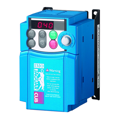
  9. i-MO JAGUAR CUB CM Series User manual

i-MO JAGUAR CUB CM Series User manual

This manual suits for next models

5

Other i-MO Inverter manuals

i-MO HD2 IP Series User manual

i-MO

i-MO HD2 IP Series User manual

i-MO iDrive2 XKL User manual

i-MO

i-MO iDrive2 XKL User manual

i-MO iDrive EDX 100V series 1-ph/0.2 - 0.75kW (0.25 -... User manual

i-MO

i-MO iDrive EDX 100V series 1-ph/0.2 - 0.75kW (0.25 -... User manual

i-MO iDrive User manual

i-MO

i-MO iDrive User manual

i-MO iDrive-EDX Series User manual

i-MO

i-MO iDrive-EDX Series User manual

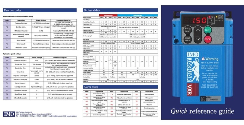
i-MO Jaguar CUB3A-1 User manual

i-MO

i-MO Jaguar CUB3A-1 User manual

i-MO Jaguar CUB User manual

i-MO

i-MO Jaguar CUB User manual

i-MO Jaguar VXM User manual

i-MO

i-MO Jaguar VXM User manual

i-MO VXSM75-1 User manual

i-MO

i-MO VXSM75-1 User manual

i-MO Jaguar VXR3A-1 User manual

i-MO

i-MO Jaguar VXR3A-1 User manual

Popular Inverter manuals by other brands

Omnik New Energy Omniksol-1.5k-TL user manual

Omnik New Energy

Omnik New Energy Omniksol-1.5k-TL user manual

Agilent Technologies 33250A user guide

Agilent Technologies

Agilent Technologies 33250A user guide

4-noks ZR-SWITCH-RC instruction manual

4-noks

4-noks ZR-SWITCH-RC instruction manual

V&T V5 Series user manual

V&T

V&T V5 Series user manual

Hon Turing HT-T-S1000-12 introduction

Hon Turing

Hon Turing HT-T-S1000-12 introduction

Metabo E 140 SP Plus Original operating instructions

Metabo

Metabo E 140 SP Plus Original operating instructions

BARRON EXITRONIX Tucson Micro Series installation instructions

BARRON

BARRON EXITRONIX Tucson Micro Series installation instructions

Baumer HUBNER TDP 0,2 Series Mounting and operating instructions

Baumer

Baumer HUBNER TDP 0,2 Series Mounting and operating instructions

electroil ITTPD11W-RS-BC Operation and Maintenance Handbook

electroil

electroil ITTPD11W-RS-BC Operation and Maintenance Handbook

Silicon Solar TPS555-1230 instruction manual

Silicon Solar

Silicon Solar TPS555-1230 instruction manual

Mission Critical Xantrex Freedom SW-RVC owner's guide

Mission Critical

Mission Critical Xantrex Freedom SW-RVC owner's guide

HP 3312A Operating and service manual

HP

HP 3312A Operating and service manual

Hoymiles HM-500T user manual

Hoymiles

Hoymiles HM-500T user manual

Nitecore SPM10 user manual

Nitecore

Nitecore SPM10 user manual

AEG Protect PV installation manual

AEG

AEG Protect PV installation manual

On Board TruePower Plus 1200MS owner's manual

On Board

On Board TruePower Plus 1200MS owner's manual

Plugreen PGM-200P-230 Installation and operation manual

Plugreen

Plugreen PGM-200P-230 Installation and operation manual

Fourgroup Easy use and Programming Handbook

Fourgroup

Fourgroup Easy use and Programming Handbook

manuals.online logo
manuals.online logoBrands
  • About & Mission
  • Contact us
  • Privacy Policy
  • Terms and Conditions

Copyright 2025 Manuals.Online. All Rights Reserved.

SINGLE PHASE MICRO-VERTER 0.2 - 2.2KW
Guarantee
Year
Caution
This publication
is only to be
used as a guide.
Please seek the full
instruction manual
before installation.
If in doubt please
call IMO on
020 8452 6444 or
visit our website on
www.imopc.com
(Please refer to inside back
cover for further details)
Index
2
Features and Conformities
4
Applications
5
Specifications and Characteristics
6
Common Specifications
7
Terminal Designation
8
Basic Electrical Connections
9
The Keypad
11
Main Functions (F)
12
Other Functions (E,C,H)
13
Protective Functions
14
External Dimensions
15
Options
17
Wiring Equipment
18
Warranty, Safety Precautions, and Help Lines
1
Guarantee
Year
2
Great performance in a compact package.
IMO Jaguar low-noise inverters:
Specifications for the new generation.
Environment-friendly features
• Utilizes a low-noise control power supply system which
minimizes noise interference on peripheral devices
such as sensors.
• Minimal motor noise driving whether high carrier
frequency (lower-noise) or low carrier frequency
is selected.
• Equipped with terminals for connecting DC REACTOR for
harmonics suppression.
Conventional inverter
CUB CM
Noise level [dB]
20
30
40
50
60
70
0 102030405060
Frequency [Hz]
20
30
40
50
60
70
0 102030405060
Frequency [Hz]
PID control function: for fans
and pumps
•Complete with a PID control function which can
optimise the flow rate of fans and pumps.
Compact
•Only 80mm wide and 120mm high (up to 0.75kW): can
be installed easily in panels.
•Mountable on 35mm IEC compliance rails using the
optional rail mounting base (up to 0.75kW).
Conformity to Low Voltage Directive
The Jaguar CUB CM Series conforms to the Low
Voltage Directive with EN50178.
Conformity to EMC Directive
• Emission requirement
EMC filters in compliance with EN61800-3 are
provided for all models as an optional extra
• Immunity requirement
The Jaguar CUB CM Series inverters meet
EN61800-3 as standard.
3
Easy operation and simple,
wiring
•Equipped with a large potentiometer (on the
front of the inverter) which sets output
frequency.
•Control through various input signals: from
0 to 10V DC, from 0 to 5V DC, and from 4 to
20 mA.
•Separated main circuit input terminals and
output terminals, arranged at the top and the
bottom of the inverter for confusion-free
connections.
•Easy to wire control inputs/outputs.
Serial communication
(RS485)
•Serial data communication conforming to
RS485 through the optional personal
computer interface card.
Other useful features
•Compliant with major world safety
standards: UL, cUL, TÜV, EN (CE
marking) standards.
•Equipped with inrush current control
circuit in order to protect magnetic
contactor.
•Records accumulated operation time.
•Cooling fan stop operation to increase fan
life, reduce its air noise and save energy.
JAGUAR CUB CM
4
JAGUAR CUB CMAPPLICATIONS
Other applications
•Machine tool coolant pumps
•Screw feeders
•Industrial washing machines
•Palletisers
•Jaccuzzis
•Labelling machines
•Filling machines
•Spindle drives
•Potato sorters
•Boiler temperature control
•Automatic shutter doors
•Wood turning lathes
•Tread mills
•Labelling machines
•Vibrators
•Classifiers
•Knitting machines
Controlling fans and pumps using variable speed to save energy
The PID* control function lets the inverter optimally control air conditioning systems and various types of fans The CUBCM can
also accurately control pump speeds.
*Proportional, Integral, Derivative
Conveyors
Adjusting the conveyor speed according to cycle time.
Mixers
Variable speed control of agitators and separators.
FREQ.SET
WARNING
RISK OF ELECTRIC SHOCK
Refer to user manual
before installation and
operation
Do not remove this
cover while applying
power and at least 5
min. after disconnecting
Note: Run and stop keys
function only in keypad
operation mode (when
function code FO2 setting
is 0, 2 or 3)
RUN
PRG
RESET
FUNC
DATA STOP
5
Torque characteristics
STANDARD SPECIFICATIONS
120
150
100
80
65
50
200V/50Hz
0320 50 100
Short time operation torque
(high torque boost)
Continuous operation torque
100% of output torque refers to
the rated torque of the motor
driver at 50Hz.
Output torque [%]
Output frequency [Hz]
Type Jaguar CUB CM – 0.2 0.4 0.75 1.5 2.2
Nominal applied motor kW – 0.2 0.4 0.75 1.5 2.2
Output Rated capacity *1) kVA 0.53 0.95 1.5 2.6 3.8
ratings Rated voltage *2) V 3-phase, 200V/50Hz; 200, 220, 230V/60Hz
Rated current *3) A – 1.4 2.5 4.0 7.0 10.0
Overload capability 150% or rated current for 1 minute
Output frequency Hz 0.1 – 120
Input Phases, Voltage, Frequency l-phase, 200 to 240V, 50/60Hz
ratings Voltage/frequency variations • Voltage: +10 to -10% • Frequency: +5 to -5%
Momentary voltage dip When the input voltage is 165V or more, the inverter can be operated continuously
capability When the input voltage drops below 165V from rated voltage, the inverter can be operated for 15ms
(less than 85% load of nominal applied motors)
Rated (with DCR) – 2.0 3.5 6.5 11.8 17.7
current *4) (without DCR) – 3.9 6.4 11.4 19.8 28.5
Required power
supply capacity *5) kVA – 0.4 0.7 1.3 2.4 3.6
Braking
Torque (standard) *6) 150% 100% 50% 30%
DC injection braking • Starting frequency: 3.0Hz (Fixed) • Braking time: 0.0 to 30.0s • Braking level: 0 to 100% of rated current
Enclosure (IEC 60529) IP 20
Cooling method Natural cooling Fan cooling
Standards • UL/cUL, Low Voltage Directive, EMC Directive
• IEC 61800-2 (Rating, specifications for low voltage adjustable frequency a.c. power drive systems)
• IEC 61800-3 (EMC product standard including specific test methods)
Mass kg – 0.6 0.7 0.9 1.6 2.2
*1) Inverter output capacity (kVA) at 220V. *2) Output voltage is proportional to the power supply voltage and cannot exceed the power supply voltage. *3) Current derating may be required in
case of low impedance loads such as high frequency motor. *4) This value is calculated using IMO calculation method. (Refer to Technical Information). *5) When a power-factor correcting DC
REACTOR is used. *6) With a nominal applied motor, this value is average torque when the motor decelerates and stops from 60Hz. (It may change according to motor loss).
Single-phase 200V series
6
JAGUAR CUB CMCOMMON SPECIFICATIONS
Item Explanation
Output Maximum frequency 50 to 120Hz (in 1Hz steps)
frequency Base frequency 50 to 120Hz (in 1Hz steps)
Starting frequency 1 to 6Hz (in 1Hz steps)
Carrier frequency 0.75 to 15kHz
Accuracy (Stability) • Analog setting : ±1.0% of maximum frequency (at 25 ±10˚C)
• Digital setting : ±0.01% of maximum frequency (at -10 to +50˚C)
Setting resolution • Analog setting : 1/256 of maximum frequency ex.) 0.25Hz at 60Hz, 0.5Hz at 120Hz
• Digital setting : 0.01Hz at maximum frequency of up to 99.9Hz (1Hz at maximum frequency of 100Hz and above)
Control Control method •
Sinusoidal PWM control
Voltage/freq. (V/f) characteristic
Maximum output voltage proportional to line input voltage (without AVR control)
Torque boost Manual: Code selection (0 to 31), including the save energy pattern for variable torque load
Starting torque 150% (at 6Hz) (Torque boost code (F09) is 20 and above.)
Operation method • KEYPAD operation : key, key
• Digital input signal operation : FWD or REV command
• LINK operation : RS485 (Option)
Frequency setting • KEYPAD operation : or key
• Built-in potentiometer: Potentiometer is standard equipment
• Analog input: 0 to +10VDC (0 to +5VDC)
v to 20mADC
• Multistep frequency: 4 different frequencies can be selected by terminal (SS1) and (SS2).
• LINK operation: RS485 (Option)
Running status signal Relay output: Alarm output for any fault. (1SPDT)
Analog output: Output frequency, output current, PID feedback value, DC link circuit voltage
Acceleration time 0.0 to 60s (0.0 = 0.01s)
Deceleration time 0.1 to 60s
Frequency limiter High and low limiter can be preset.
Bias frequency Bias frequency can be preset (-120 to 120Hz)
Gain for frequency setting
100% (For 0 to +10VDC) or 200% (For 0 to +5VDC)
Jump frequency control Jump frequency (3 points) and its common jump hysteresis width (0 to 30Hz0 can be preset
Auto-restart after Automatic restart is available after a momentary power failure (retry method)
momentary power failure
PID control This function can control flow rate pressure, etc. (with an analog feedback signal.)
• Reference signal (F01): • KEYPAD operation ( or key)
• Voltage input (Terminal 12)
• Current input (Terminal C1)
• Analog input (Built-in Potentiometer)
• Feedback signal (H21) • Terminal 12 (0 to +10V DC or 1 to 5V DC)
• Terminal C1 (4 to 20mA DC)
Indication Operation mode • Output frequency, output current, PID reference value, PID feedback value
(running or stopping • Setting frequency
Program mode Function code, data code
Trip mode Displays trip fault code as follows
• OC1 (Overcurrent during acceleration)
• OC2 (Overcurrent during deceleration)
• OC3 (Overcurrent running at constant speed)
• OU1 (Overvoltage during acceleration)
• OU2 (Overvoltage during deceleration)
• OU3 (Overcurrent running at constant speed)
• LU (Low voltage)
• OH1 (Overheating at heatsink)
• OH2 (External thermal relay tripped)
• OL (Motor overload)
• OLU (Inverter unit overload)
• Er1 (Memory error)
• Er3 (CPU error)
• Er8 (RS485 error)
Operation and Trip mode Trip history (passed/4 times
Charge lamp (Red) When the DC link circuit voltage is higher than 50V,. the charge lamp is ON
Protection Overload Protects the inverter by electronic thermal overload relay and detection of inverter temperature
Overvoltage detection Detects DC link circuit voltage (400V), and stops the inverter
Undervoltage Detects DC link circuit undervoltage (200V) and stops the inverter
Overheating Protects the inverter by detection of inverter temperature
Short-circuit Short-circuit protection for inverter output circuit
Ground fault Ground fault protection for inverter output circuit (detection at starting)
Motor overload • Protects the motor after the inverter trips
(running or stopping • Electronic thermal overload relay can be selected for standard motor or IMO inverter motor
Stall prevention
• Controls the output frequency to prevent (overcurrent) trip when the output current exceeds the limit value during acceleration
• Lowers the output frequency to hold almost constant torque when the output current exceeds the limit value during operation at constant speed
• Controls the output frequency to prevent (overvoltage) trip when the DC link circuit voltage exceeds the limit value during deceleration
Auto reset When the inverter is tripped, it resets automatically and restart. 5-times auto reset can be selected
Condition Installation location Free from a dusty location, corrosive gases, oil mist and direct sunlight. Indoor use only
(Installation Altitude 1000m or less. (Applicable to 3000m with power derating: -10%/1000m)
and
Ambient temperature -10˚ to +50˚C
operation)
Ambient humidity 5 to 95% RH (non-condensing)
Vibration 3mm at 2 to 9Hz, 1m/s2at 9 to 200Hz
Storage conditions • Temperature: -25˚ to +65˚C • Humidity: 5 to 95% RH
Setting
7
TERMINAL DESIGNATION
Symbol Terminal name Function Remarks
Func. code
Main
L1/L, L2/N
Power input Connect 1-phase 200V power supply
circuit U, V, W Inverter output Connect 3-phase induction motor
P1, P(+) For DC REACTOR Connect the DC REACTOR (option) for power-factor
correction or harmonic current reduction
G Earth Terminal for inverter chassis
Analog 13 Potentiometer +10VDC power supply for setting potentiometer (POT: 1 to 5kΩ) Allowable maximum output currrent: 10mA
input 12 Voltage input 0 to +10VDC/0to 100% (0 to +VDC/0 to 100%) • Input impedance: 22kΩF01
• Allowable maximum input voltage: 50mA
• If input voltage is 10 to 15VDC, then the inverter
clamps it at 10VDC
(PID control) Used for PID control reference signal or feedback signal
F01, H21
C1 Current input 4 to 20mA DC/0 to 100% • Input impedance: 250ΩF01
• Allowable maximum input current: 30mA DC
• If input voltage is 20 to 30mA DC, then the
inverter clamps it at 20mA DC
(PID control) Used for PID control feedback signal or reference signal
F01, H21
11 Common Common for analog signals Same potential as CM – 0V
Digital FWD Forward operation FWD – ON ........ The motor runs in the forward direction When FWD and REV are simultaneously ON, the F02
input command FWD – OFF ...... The motor decelerates and stops motor decelerates and stops
REV Reverse operation REV – ON ........ The motor runs in the reverse direction When FWD and REV are simultaneously ON, the
command REV – OFF ...... The motor decelerates and stops motor decelerates and stops
X1 Digital input 1 These terminals can be preset as follows • Sink type terminal specifications E01 to
X2 Digital input 2
• ON state maximum input voltage: 2V E03
X3 Digital input 3
(maximum source current: 6mA)
• OFF state maximum terminal voltage: 24 to 27V
(allowable maximum leakage current: 0.5mA)
(SS1) Multistep freq. (SS1): 0, 1 different frequencies can be selectable 0 frequency (All (SS1) and (SS2) signals are OFF) C05 to
(SS2) select (SS1, SS2): 0 to 3 different frequencies can be selectable is set by “F01” C07
(BX) Coast-to-stop (BX) – ON ...... Motor will coast-to-stop • The motor restarts from 0Hz by turning off BX
command (No alarm signal will be output)
with the operation command (FWD or REV) ON
• Assigned to terminal X2 at factory setting
(RST) Alarm reset (RST) – ON ...... Faults are reset • During normal operating, this signal is ignored
(This signal should be held for more than 0.1s) • Assigned to terminal X3 at factory setting
(THR) Trip command (THR) – OFF ...... “0H2 trip” occur and motor will coast-to-stop This alarm signal is held internally
(External fault)
(WE-KP) Write enable for (WE-KP) – ON ...... The data will be changed by KEYPAD panel F00
KEYPAD
(Hz/PID) PID control cancel (Hz/PID) – ON ...... The PID control is cancelled and KEYPAD panel frequency H20 to
setting ( or ) is effective H25
(LE) Link enable (LE) – ON ...... The link operation is effective For switch link operation to communication
(RS485: Option)
P24/CM
P24: DC voltage supply
DC voltage supply (+24V, max 100mA) DIPSW select: SW7
11 CM: common Common for digital signal Same potential as 11
Analog FM Analog monitor • Output voltage (0 to 10VDC) is proportional to selected function’s value as follows Allowable maximum output currrent: 2mA F30,
output .Output frequency (0 to max. frequency) F31
.Output current (0 to 200%)
.PID feedback value (0 to 100%)
.DC link circuit voltage
11 (Common) • Bias value can be preset
Relay 30A, 30B Alarm relay Outputs a contract signal when protective function is activated Contact rating: F36
output 30C output Changeable exciting mode active or non-exciting mode active by function No. F36 • 250V AC, 0.3A, cos ø=0.3
• 48VDC, 0.5A, non-inductive
Applicable maximum voltage for CE marking
(Low Voltage Directive)
Applicable maximum voltage for UL/cUL
Terminal functions
Terminal arrangement
30A 30B 30C FM X1 X2 X3 FWD REV
P24/CM
11 12 13 C1
G L1/L L2/N P1 P(+)
GN(-) U V WP(+)
●Main circuit terminals
Input 1-phase
Output 3-phase
●Control circuit terminals
8
JAGUAR CUB CMBASIC ELECTRICAL CONNECTIONS
Keypad panel operation
The following diagram is for reference only.
For detailed wiring diagrams, refer to the relevant instruction manual.
External operation
The following diagram is for reference only.
For detailed wiring diagrams, refer to the relevant instruction manual.
Connect the inverter to the power supply and the motor. Then,
turn on the power to enable variable-speed operation.
Notes:
1) To operate the inverter using the factory-settings, proceed as
follows:
(1) Start/stop........................Press or key on the
keypad panel. (*2)
(2) Setting frequency...........Use the frequency setting
potentiometer (VR) on the keypad
panel.
2) To enable and keys for frequency setting, select
function code F01 and change the data from 4 to 0. Change of
the data code disables the VR (frequency setting
potentiometer).
3) Keep the control circuit wires at least 100 mm away from the
main circuit wires and put them in separate ducts to prevent
high frequency coupling and resultant malfunctions.
Where control wiring crosses the main wiring, ensure that they
cross each other at right angles.
4) For the wiring of the control circuit, use shielded or twisted
pairs with the shortest possible length. (When using shielded
wires, connect one end of the shields to the inverter ground
terminal and leave the other end free.)
5) If there is a magnetic contactor or a solenoid close to the
inverter, mount a surge absorber to the coil in a parallel
connection. Keep the wiring length to a minimum.
*1 When connecting the optional DC reactor, remove the jumper wire from between
P1 and P(+).
*2 Drive will run in forward direction as set in factory.
Notes:
1) This wiring diagram shows the connection for stopping the
inverter or setting frequency through external signals.
When “1” is set at F01, you can set a frequency by using input
signal from 0 to 10V DC. When “2” is set at F01, you can set a
frequency by using an input signal between 4 and 20mA.
In this case, set “1” at F02.
2) If there is a magnetic contactor or a solenoid close to the
inverter, mount a surge killer to the coil in a parallel
connection. Keep the wiring length to a minimum.
3) To wire the control circuit, use shielded or twisted wires. When
using shielded wires, connect the shields to G.
4) Control logic is selectable as sink/source by position of switch
SW7 on pcb ie. SW7 = UP, inputs are referenced to onboard
power supply P24 (24 VDC). SW7 = DOWN, inputs require
external power supply and are referenced to zero volts at
inverter CM terminal.
*1 When connecting the optional DC reactor, remove the jumper wire from between
P1 and P(+).
U
V
W
*Motor
M
13
12
11
C1
FWD
REV
X1
X2
P24/CM
X3
FM
P(+)
N(-)
30A
30B
30C
G
*: Option
Alarm relay output
P1
P(+)
P1
P(+)
E
When DC
REACTOR is used
(*1)
G
30
L1/L
L2/N
Power supply
1-phase 200 to 240V
50/60Hz
*MCCB
or
ELCB
FILTER
.
U
V
W
*Motor
M
13
12
11
C1
FWD
REV
X1
X2
P24/CM
X3
FM
P(+)
N(-)
GG
Alarm relay output
SW7 (see note 4)
P1
P(+)
P1
P(+)
E
When DC
REACTOR is used
Analog meter
Analog monitor
To Terminal No. 11
To G
Frequency set
voltage input
(0 to 10V DC)
Frequency set
current input
(4 to 20mA DC)
Forward operation
command
Reverse operation
command
*: Option
(*1)
30A
30B
30C
30
3
2
1
L1/L
L2/N
Power supply
1-phase 200 to 240V
50/60Hz
*MCCB
or
ELCB
FILTER
.
P24
CM
Warning – Inverter must be earthed.
Input wiring must be protected against short/earth faults.
Warning – Inverter must be earthed.
Input wiring must be protected against short/earth faults.
9
KEYPAD PANEL FUNCTIONS AND OPERATION
Keypad panel
Keypad panel operation method
Digital monitor
In Operation mode: Displays output
frequency,*1or output current.
In Stop mode: Displays the set
frequency. *2
In Program mode: Displays function
codes and data codes.
In Trip mode: Displays code indicating
the cause of the trip.
Program/Reset key
Switches between operation mode and
program mode.
When tripped: Releases the trip-stop
state and changes to operation mode
after the cause of trip has been
removed.
Function/Data key
In Operation mode: Switches the
display between output frequency and
output current.
In Stop mode: Switches the display
between set frequency and set current.
In Program mode: Sets data for
function codes.
Some function code data can be
changed during operation.
Up/Down keys
In Operation mode: Increases or
decreases frequency (motor speed).
In Program mode: Increases or
decreases function code number and
data set value.
Run key
Starts the inverter output.
In Stop mode:
Inactive when the function code
is set to (external operation).
Stop key
Stops the inverter output.
In Operation mode: Invalid when the
function code is set to
(external operation).
Frequency setting potentiometer
Increases or decreases the frequency.
Active only when the function
code is set to (inverter
on-board pot).
1. Turn on the power supply. The monitor shows data as illustrated above.
When you press the key, the inverter gradually increases the frequency until 60Hz is reached to rotate the
motor clockwise according to the factory-settings. To stop the motor, press the key.
To increase or decrease the operation frequency, adjust the frequency setting pot. For wiring connections, refer to the
basic wiring diagram on page 8.
2. Selecting function codes and changing data codes
To select the function code and change the data code, proceed as follows:
●Press the key to select the program mode.
●Pressing the key alternates the displayed data between the function code and its data.
●With data displayed, press the key to change the data code.
●Press the key to update the data for the selected function code.
* In step 2, if the key is pressed when the function code is displayed, only the function code changes
sequentially (see below).
( ....)
*1 When PID control operation (H20:1 or 2) is selected, the monitor displays the PID feedback value instead of the output frequency.
*2 When PID control operation (H20:1 or 2) is selected, the monitor displays the PID reference value instead of the set frequency.