Felisatti MTF 216/1100T User manual


TECHNICAL DATA
Mitre saw MTF216/1100T MTF250/1500T
Absorbed power W 1100 1500
No-load speed / min 5000 4300
Cut at 90º/mitre (AxB Fig.4 a) mm 58x133 70x150
Cut at 45º/mitre (AxB Fig.4 b) mm 58x90 70x85
Cut at 90º/blade at 45º (AxB Fig.4 c) mm 35x1330 47x150
Cut on upper bench mm 31,5 45
Upper bench dimensions mm 224х358 264х385
Blade diameter mm 216 250
Blade hole diameter mm 20(30) 20(30)
Weight Kg 9,5 11
Overall dimensions (LxHxW) mm 427x277x531 460х450х300
Acoustic pressure, Lpa dBA 96 92
Sound power emitted, Lwa dBA 109 105
Vibration level (according to ISO 8041 and ISO 5348) m/sec2 2,5 3,9
Carefully observe the instructions in this manual, keep it in a safe
place at hand for any possible checks on the parts indicated.
If the tool is used with care and a normal maintenance is carried
out, it will have a long life.
GENERAL INFORMATION
DENTIFICATION (See indicated gures)
A Saw penetration adjustment screw (Fig.1a)
B Uptake connection nozzle (Fig.1,1a)
C Pushbutton switch (Fig.1)
D Safety hook release button (Fig.1)
E Switch lock button (Fig.1)
F Upper bench saw protector (Fig.3)
G Upper bench (Fig.1,1a)
H Upper bench blocking handles (Fig.2)
I Saw blade (Fig.1,2)
J Mobile guard (Fig.1)
K Turntable (Fig.1)
L Base (Fig.1,3)
M Fixed guide (Fig.1)
O Motor unit blocking lever (Fig.1)
P Position lock pin (Fig.1a)
Q Fixed saw protection, extractable (Fig.1а)
Q1 Protection button (Fig.1,1a)
R Scale index (Fig.1)
R1 Graduated scale for turning the motor unit (Fig.1)
R2 Graduated scale turntable (Fig.1)
S Guide xing buttery (Fig.1,2)
T Upper bench guide (Fig.1,3)
V Handles (Fig.3) (Optional accessory)
Y Bench xing bolt (Fig.1) (internal)
Z1 Adjustment bolt (Fig.1a)
Z2 AC cable (Fig.1)
Z3 Brush holder cover (Fig.1)
Z4 Clamp (Fig.5) (Optional accessory)
TECHNICAL CHARACTERISTICS
The robust and highly reliable structure makes these mitres
suitable for cutting wood, aluminium and steel in industrial
environments, while preserving their usual ease of handling and
without restricting their movement.
The MTF216/1100T and MTF250/1500T are tted with a wide
upper table that allows the mitre saw to be transformed into a
table saw to carry out cutting (up to a thickness of 45 millimetres).
The MTF216/1100T and MTF250/1500T are tted with two
working tables (upper and lower), and have been provided with a
switch to keep the circuit on while pressing, and a lock-on button
for free-hands operation when working on the upper bench.
The MTF216/1100T and MTF250/1500T are tted with a
new electronic device to prevent the machine from starting
unexpectedly after a break in the voltage supply. When this
happens, to restart you must oper-ate the switch to switch-off
and then to switch-on.
A single operator is needed to use the mitre saw, of which the
design and construction comply with stan-dards EN 61029-1 and
EN 60204-1.
SAFETY DEVICES
• Atrest,thebladeistotallycoveredbytwoprotec-tors,
one xed and one mobile, which are automati-cally opened by
the descent of the blade unit when cutting.
• On the upper bench, the blade is covered by one protection

which is raised by the work when it comes close to the cut.
WARNING – these protectors must not be removed, in order
to prevent danger for the operator.
• In the event that the switch lock button has not been
engaged, the machine will stop automatically when the
handgrip is released.
WARNING – engaging the lock button disables the safety
device provided by the manufacturer and enables push-
buttonstart.Itisrecommendedthatthisdevicebeusedwith
theutmostcaution.
The tool has been designed and built so that it is possible to
work in all situations with total safety, however, in special working
conditions, gloves and protective goggles should be worn.
The tool has been designed and built to reduce noise to a
minimum (see technical data), however, in special conditions the
maximum noise level in the workplace might exceed 85 dB(A).
In this case, the operator should protect himself from excessive
noise by using ear protectors.
GENERAL SAFETY REGULATIONS
See manual “Safetyinstructions” which is supplied together
with this instructions manual.
INSTALLATION
1. ELECTRICAL CONNECTION
Before connecting the machine to the mains, one must make sure
that it complies with current regula-tions in the country where it is
used and that the voltage and frequency are as indicated on the
char-acteristics plate.
When extensions are used, make sure that the cross section of
the cables is suited to their length. If using roll up extensions,
make sure that they unroll completely in order to prevent
overheating.
WARNING–beforeplugginginthemachine,makesurethat
theswitchlockbuttonisreleased.
2. WORKPLACE
The tool that you have purchased is a transportable or semi-
stationary electric tool. Only one operator is needed to use it,
given its structure, weight and ease of handling.
In normal use, the operator is in front of the machine with the
handle to his right. The right hand on the handle allows the
machine to be handled completely, in fact, the switch and a safety
hook may be accessed without releasing the handle.
CONSTANT ELECTRONICS
The built-in module permits:
- Soft start.
- The maintenance of a practically constant rated speed up to
rated power.
- An overload protection system by means of current cut-off
in the case of motor overload, in which case the burring machine
shuts down and re-starts when the grinding pressure has been
reduced.
MITRESAWADJUSTMENT-SQUARING
The mitre is delivered by the manufacturer already adjusted and
squared according to standard pa-rameters.
WARNING – before making any adjustment of the mitre,
unplugthemachine.
1. BLADE UNIT LIFTING
An internal spring keeps the motor unit at rest position (raised).
In this position, a safety hook prevents the unit from being
activated accidentally.
1.1 To unlock the motor unit and to be able to use the machine as
a mitre saw, activate the front button D(Fig.1) (the operation may
be carried out with the right hand on the handle).
1.2. To use the machine as a bench circular saw, unlock the
motor unit as indicated in 1.1, and after lowering it completely,
block it with pin P(Fig.1a).
2. BLADE PENETRATION ADJUSTMENT
The depth of penetration has already been adjusted by the
manufacturer during testing.
As incorrect adjustment may cause sharpness to be lost quickly
and/or the teeth of the blade to be broken, further adjustment
might be needed, in which case it will be necessary to work as
follows:
- Activate bolt A (Fig.1а) and the corresponding lock nut to
create a lower limit for the motor housing ideal for preventing
the blades from coming into contact with the turntable.
WARNING–onceforthisoperationiscomplete,makesure
thatthebladeisNOTincontactwiththeturntableandthat
thelocknutistightened.
3. TURNTABLE ADJUSTMENT
0ºRegulation(Fig.3)
- Lower the head of the machine and lock with pin P (Fig.1a).
- Set the turntable to zero.
- Loosen the handles V, remove the guides X– Optional
accessory and loosen bolts Y.
- Set a square between the saw blade and guide M (Fig.1).
- Keeping the turntable at zero, move the guide to 90º on the
square.
- Tighten bolts Y, assemble guides X and adjust handles V –
optional accessory.
4. ADJUSTING THE SAW BLADE WITH RESPECT TO THE
WORKING PLANE
90ºadjustment(Fig.2)
- Lower the head of the machine and lock with pin P (Fig.1a)
- Place a square between the base and the saw blade.
- Loosen lever Oand adjust with bolt Z.
- Tighten the lock nut well to make sure that the position is
xed and tighten lever O.
5. VERTICAL PLANE LIMIT STOP ADJUSTMENT (0º - 45º)
(Fig.2)
- Lower the head of the machine and lock it with pin P
(Fig.1a).
- Set the turntable to zero and lock.
- Set the head to 45º and lean a 45º square between the base
and the saw blade.
- Loosen lever Oand adjust using bolt Z.
- Regulate the 45º using bolt Z1 (Fig.1a), after releasing the
lock nut.

- Tighten the lock nut to make sure that the position does not
change.
OPERATION AND USE
1. CUTTING WITH THE BLADE AT 90º AND TURNTA-BLE
TURNED
- Unlock the turntable K(Fig.1) by turning lever Yto the left.
- Turn the turntable with the handle, selecting the cutting
angle required using the graduated scale R2 and index R
(Fig.1), and lock again by turning lever Y(Fig.1) to the right.
Note: there are pre-set cutting angles (0º, ±15º, ±22º30’, ±30º,
±45º) on which the turntable may easily be locked.
2. CUTTING WITH THE BLADE INCLINED AND TURNTABLE
AT 0º (Fig.6) (Optional accessory)
- Move guide Xoutwards, in the direction of the arrow, or
even out of the machine for better operation. - R e l e a s e
the motor unit by loosening lever O(Fig.1).
- Turn the motor unit, selecting the required inclination using
the graduated scale R1 (Fig.1) and lock lever Oonce more.
3. USE OF THE MITRE SAW
WARNING–MakesurethatthelockbuttonE(Fig.1)isinthe
releaseposition.
- Set the upper bench to the maximum height.
- Always start with the motor unit in rest position (raised with
the safety hook tted)
- Fix the material to be cut rmly to the cutting plane.
- Start and wait for the blade to reach maximum revolutions.
- Press the button releasing the motor unit.
- Gradually lower the motor unit and cut.
4. BLADE START AND STOP
WARNING – make sure that the moving protector is in the correct
position when the blade is at rest (raised).
The machine is provided with a switch C(Fig.1) with push button,
which is used to start and stop the blade. It is possible to block
the switch ‘ON’ by pressing the lock button E(Fig.1)
WARNING – engaging the lock button disables the safety
device provided by the manufacturer and enables push-
buttonstart.Itisrecommendedthatthisdevicebeusedwith
theutmostcautionandONLYwhenusingthemachineasa
circularsaw.
To release the switch again, it is only necessary to press the
button and release.
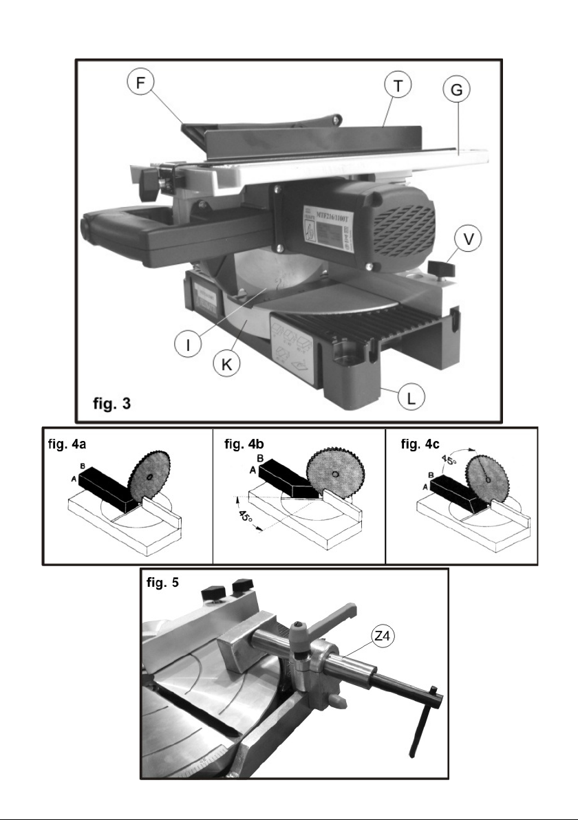
5. USE OF THE CLAMP (OPTIONALACCESSORY)
- Raise the saw to be able to place the wood board or the
aluminium pipe on the bench for cutting and in position with
respect to guide M (Fig.1).
- Fit the clamp Z4 (Fig.5) if it is not already tted, and turn the
bolt until the clamp press rmly on the piece to be cut, making
sure that it do not move, to avoid any accident.
- Once the operation is complete, loosen the clamp to release
the piece and change the position for the next job.
6. USE OF THE UPPER BENCH
To use the upper plane, proceed as follows:
- Make sure that the lock button E (Fig.1) is released
(standing out).
- Lower the blade unit completely and lock with pin P (Fig.1a).
- Release handles H (Fig.2) and select the height of the
upper plane, proceeding to lock the handles once more.
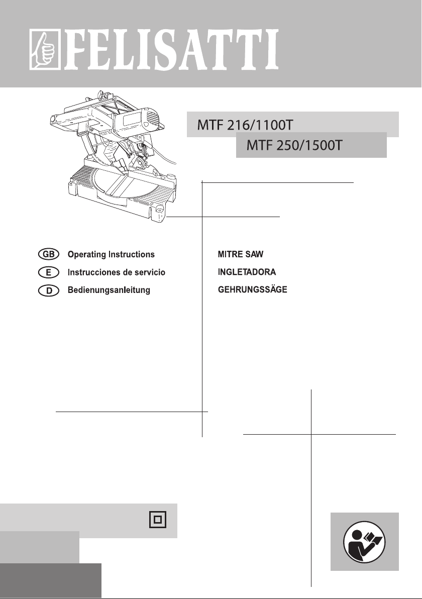
7. USE OF THE STOP GUIDE FOR THE UPPER BENCH (Fig.7)
Use as follows:
- Insert guide Tin the upper bench.
- Select the cutting width.
- Lock guide T by tightening buttery U followed by buttery
S.
8. MISCELLANEOUS ACCESSORIES
The machine is supplied with the uptake nozzle included B
(Fig.1) and may therefore be connected easily to any vacuum
cleaner.
9. MISUSE
The functions and use of the tool that you have bought are only
as indicated in this manual.
Any other use of the tool is entirely prohibited.
• Do not cut aluminium or steel on the upper plane.
• Always use sharp blades suitable for the cut to be made.
• Do not use the machine without the described protection.
• Not suitable for foodstuffs.
• Use the machine only for cutting wood, aluminium proles,
PVC tubes, steel pipes and only with the right blade.
The cutting of any other material is entirely prohib-ited.
MAINTENANCE
WARNING-beforeanymaintenanceoperation,unplugthe
machine.
1. LUBRICATION
The mitre saw is delivered with in all moving parts of the motor
and gearbox entirely lubricated and needs no further lubrication
operations.
Regular lubrication is recommended of the joints of the moving
controls.
2. ORDINARY CLEANING
WARNING-avoidtouchingthehandlewithhandsdirtywith
oilorgrease.Insuchanevent,cleanimmediately.
- Carefully clean the machine after use with dry com-pressed
air.
3. DISPOSAL
When the life of the machine is at an end or when it can no
longer be repaired, make sure that the scrap is disposed of in
observance of current regulations in the country of use and that
the operation is undertaken by specialised personnel authorised
in the matter.
PART REPLACEMENT
WARNING – before carrying out any replacement, unplug
themachine.
1. REPLACING THE SAW BLADE I (Fig.1)
Replace as follows:
- Set the head to fully open (Fig.1)
- Raise the upper bench as far as is allowed.
- Release the moving protection Q(Fig.2) working on button
Q1 (Fig.1a) and raise completely.
- Fit the spanner provided in the holes of the clamp, keeping
the shaft locked with another tubular spanner supplied by the
manufacturer, and unscrew the left bolt until the saw blade is

released (Fig.2).
- Push the blade to the left and upwards at the same time to
remove it from its housing. Then extract downwards.
- Fit the new saw blade, making sure that the teeth are
directed towards the part indicated by the arrow on the blade
cover; t well to the shaft and lower the moving protection.
Note: if the version of the machine does not have the shaft locking
system as described (the case of the rst series manufactured),
the saw blade must be blocked using a bar or a screwdriver in
the hole of the saw blade, leaning against the rm structure of
the machine.
2. REPLACING THE BRUSHES
The brushes must be replaced after every 150 - 200 hours of
use or when they have reached a length of 5-6 mm. Go to an
authorised service centre for this change.
3. REPLACING THE SUPPLY CORD Z2 (Fig.1)
Make sure that the supply cable is in a good state and if not, go to
an authorised service centre for it to be changed.
GUARANTEE
See general Guarantee conditions printed on an adjoining sheet.
DECLARATION OF CONFORMITY
We hereby declare, under our own responsibility, that the
FELISATTI products described in this manual MTF216/1100T
and MTF250/1500T comply with the following standards or
standard documents: EN 61029-1, EN 55014 and EN 61300-3 in
accordance with EU Directives 73/23/EEC, 89/336/EEC, 98/37/
EEC and 2002/95/EEC.
Jordi Carbonell Santiago Lόpez
Wereservetherighttomaketechnicalchanges.

Interskol Power Tools S.L.
Carretera de Sant Joan de les Abadesses s/n17500 RIPOLL, (Girona), SPAIN
Tel +34972700200
Fax +34972700554
e-mail: [email protected]s
This manual suits for next models
1
Table of contents
Other Felisatti Saw manuals

Felisatti
Felisatti SCF 184/1400 User manual

Felisatti
Felisatti SCF 165/1200 User manual

Felisatti
Felisatti SRF305/1800 User manual

Felisatti
Felisatti T770 User manual

Felisatti
Felisatti P52246 User manual

Felisatti
Felisatti 1050900100 User manual

Felisatti
Felisatti SCF 184/1400 User manual

Felisatti
Felisatti NTF250/1200ST User manual
Popular Saw manuals by other brands

Rhyas
Rhyas SSM4002 Original instructions

Tormach
Tormach Autofeed Bandsaw AF50 Operator's manual

DeWalt
DeWalt DWE300 instruction manual

Bosch
Bosch 1640VS - Flush Cut VS Miter Saw Operating/safety instructions

stayer
stayer SC 210 BW operating instructions

Chicago Electric
Chicago Electric 47003 Assembly and operating instructions