Femi JOB LINE DIGITO ML 350 User manual

www.femi.it
IT
TORNIO PER METALLO
EN LATHE MACHINE FOR METAL
FR TOUR POUR LE METAL
DIGITO ML 350
8.35.61.20

2
IT
...................................... pagine 3-4-5-6-7-8-9-10-11-12-13-14-15-16-17-18-19-20-21-23÷32-51-52
EN
...................................... pages 3-4-5-6-7-8-9-10-11-12-13-14-15-16-17-18-19-20-21-33÷40-51-52
FR
...................................... pages 3-4-5-6-7-8-9-10-11-12-13-14-15-16-17-18-19-20-21-41÷50-51-52
IT
Istruzioni originali
(conservare per usi futuri)
EN
Translation of the original instructions
(please retain for future reference)
FR
Traduction des instructions originales
(conserver pour tout usage futur)
IT
MANUALE D’USO
EN
USER MANUAL
FR
MANUEL D’UTILISATION
IT
Per tutte le NOTE DI AVVERTENZA fare riferimento al documento “NORME DI SICUREZZA
GENERALI allegato.
EN
For all WARNING NOTES please refer to the attached “GENERAL SAFETY REGULATIONS”
document
FR
Pour toutes les NOTES D’AVERTISSEMENT se reporter au document « NORMES GÉNÉRALES
DE SÉCURITÉ » en annexe.
3
IT
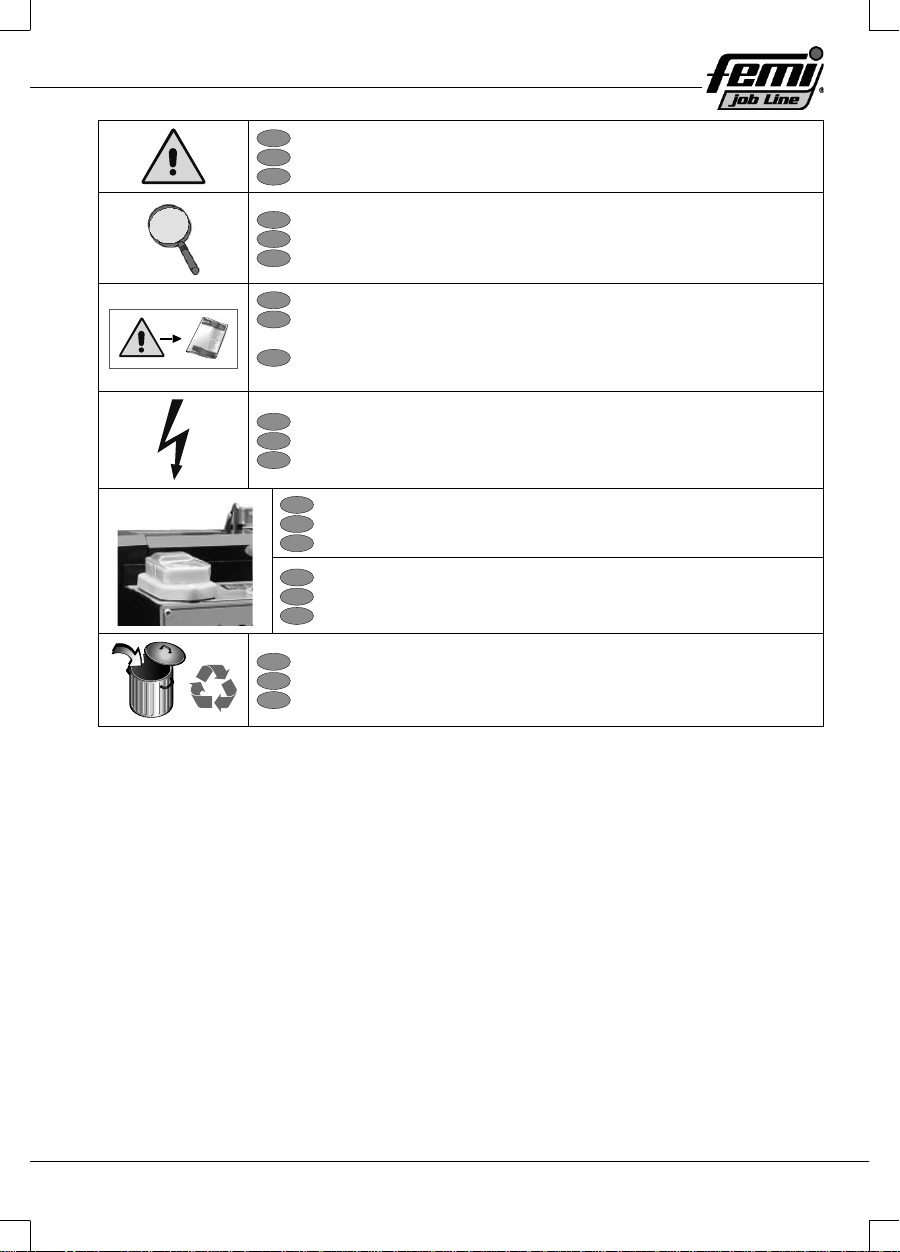
PERICOLO-ATTENZIONE!
EN
DANGER-WARNING!
FR
DANGER-ATTENTION!
IT
Nota
EN
Note
FR
Remarque
IT
Prima di procedere leggere il foglio “NORME DI SICUREZZA GENERALI”
EN
Before proceeding, please read the “GENERAL SAFETY
REGULATIONS” sheet
FR
Avant de procéder lire la notice « NORMES GÉNÉRALES DE
SÉCURITÉ »
IT
Tensione/Frequenza
EN
Voltage/Frequency
FR
Tension/Fréquence
IT
ACCENDERE la macchina
EN
SWITCH ON the machine
FR
DÉMARRER la machine
IT
SPEGNERE la macchina
EN
SWITCH OFF the machine
FR
METTRE LA MACHINE hors tension
IT
Oggetto da RICICLARE
EN
Object to be RECYCLED
FR
Objet à RECYCLER
4
IT
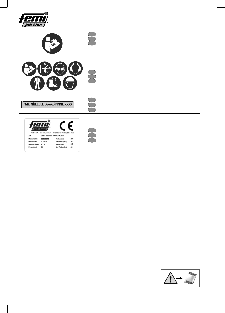
Obbligo di leggere il manuale istruzioni
EN
Read the instruction manual
FR
Obligation de lire le manuel d’instructions
IT
Utilizzo dispositivi di protezione individuali
EN
Use personal protective equipment
FR
Utilisation de dispositifs de protection individuelle
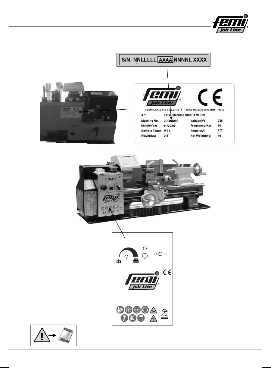
IT Matricola/Anno di costruzione
EN Serial number/Year of manufacture
FR Matricule/ Année de construction
IT
Indicazione caratteristiche e dati motore
EN
Indication of machine characteristics and motor data
FR
Indication des caractéristiques et des données du moteur
5
6
F
TO
M
P
Q
R
S
HJ
WN
B
A
K
L
U
V
D
G
C
I
E
X
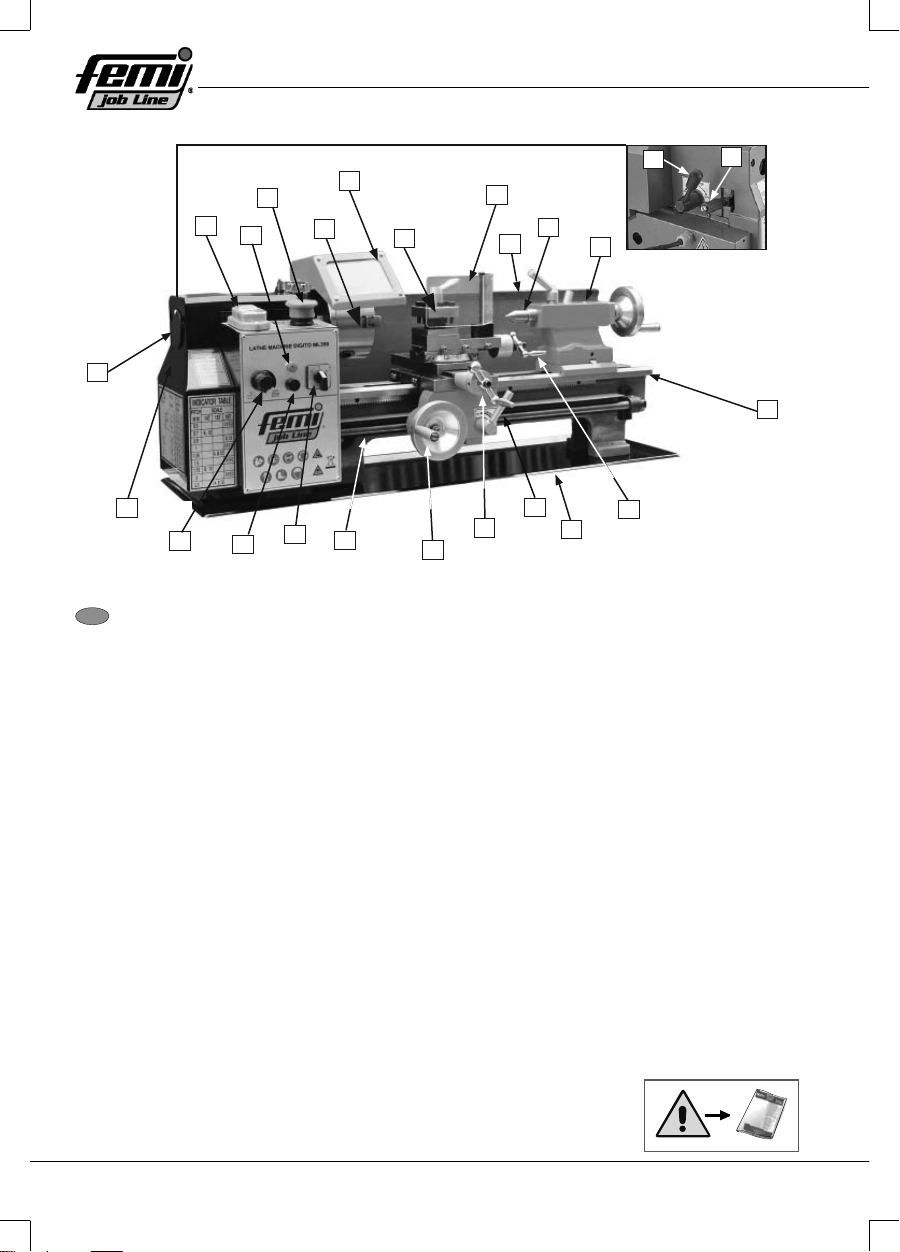
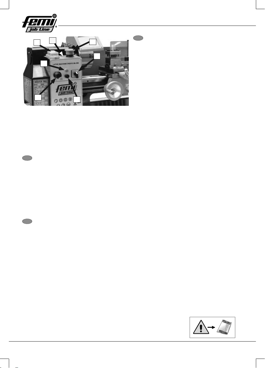
IT Identifi cazione Fig. 01
Acquisire familiarità con i nomi e le posizioni dei comandi e delle funzioni mostrati di seguito per
comprendere meglio le istruzioni contenute in questo manuale.
A. Selettore marcia veloce/lenta
B. Leva inversione-avanzamento barre
C. Interruttore ON/OFF
D. Luce accensione
E. Interruttore di arresto di emergenza
F. Mandrino a 3 griff e
G. Coperchio mandrino
M. Bancale
N. Volantino slitta porta-utensili
O. Vaschetta olio
P. Leva chiocciola spaccata
Q. Volantino slitta trasversale
R. Volantino avanzamento carrello
S. Madre vite
H. Torretta portautensile a 4 vie
T. Interruttore di direzione albero porta mandrino
I. Coperchio torretta portautensile
J. Paraspruzzi
K. Contropunta
L. Corpo Contropunta
U. Fusibile
V. Manopola regolazione velocità
W. Coperchio fi nale
X. Coperchio foro alberino

7
FR
Identifi cation
Fig. 01
Il est recommandé de se familiariser avec les noms et les positions des commandes et des fonctions
illustrées ci-dessous pour mieux comprendre les instructions contenues dans ce manuel.
A. Sélecteur vitesse rapide/lente
B. Levier inversion-avancement barres
C. Interrupteur ON/OFF
D. Témoin d’alimentation
E. Bouton-poussoir d’arrêt d’urgence
F. Mandrin à 3 griff es
G. Couvercle mandrin
M. Banc
N. Volant coulisseau porte-outils
O. Bac à huile
P. Levier demi-écrou
Q. Volant coulisseau transversal
R. Volant avancement chariot
S. Vis-mère
H. Tourelle porte-outil à 4 voies
D. Commutateur de direction arbre mandrin
I. Couvercle tourelle porte-outil
J. Écran de protection
K. Contre-pointe
L. Corps contre-pointe
U. Fusible
V. Manette de réglage vitesse
W. Couvercle terminal
X. Couvercle trou de fuseau
EN
Identifi cation Fig. 01
Become familiar with the names and locations of the controls and features shown below to better
understand the instructions in this manual.
A. High/Low Range Lever
B. Feed direction lever
C. ON/OFF switch
D. Power light
E. Emergency stop switch
F. 3-jaw chuck
G. Chuck cover
M. Bedway
N. Top slide handwheel
O. Oil tray
P. Half nut lever
Q. Cross Slide Handwheel
R. Apron handwheel
S. Leadscrew
H. 4-way tool post
T. Spindle direction switch
I. Tool post cover
J. Splash guard
K. Dead center
L. Tailstock
U. Fuse
V. Speed adjusting knob
W. End cover
X. Spindle hole cover
8
A
F
E
C
B
G
D
FR
Commandes et Composants
Tableau de commande Fig. 02
A. Interrupteur on/off : Presser « I » pour démarrer la machine, presser « O » pour arrêter la
machine.
B. Affi cheur vitesse arbre mandrin : Il fournit une lecture numérique de la vitesse de l’arbre
mandrin.
C. Bouton-poussoir d’arrêt d’urgence : Presser pour couper l’alimentation. Relâcher pour assurer
l’alimentation.
D. Commutateur de direction arbre mandrin : Il permet de démarrer, arrêter ou inverser le sens
de l’arbre du mandrin.
E. Témoin d’alimentation : Il s’allume quand la machine est branchée à une source d’énergie.
F. Fusible : Il protège le panneau de commande contre toute surcharge électrique.
G. Manette de réglage vitesse : Elle permet de régler la vitesse de l’arbre du mandrin, de petite à
grande.
EN Controls & Component
Control panel Fig. 02
A. On/Off Switch: When press “I” to start the machine, press “O” to stop the machine
B. Spindle Speed Display: Shows a digital readout of the spindle speed.
C. Emergency Stop Button: Pressed to cut power off . Released to power on.
D. Spindle Direction Switch: Starts, stops, and reverses spindle.
E. Power light: Illuminates when machine is connected to power source.
F. Fuse: Protects control panel in case of an electrical overload.
G. Speed adjusting knob: Adjusts the spindle speed from low to high.
IT Comandi e Componenti
Quadro di comando Fig. 02
A. Interruttore On/Off : Premere “I” per
avviare la macchina, premere “O” per
arrestare la macchina
B. Display velocità albero mandrino:
Fornisce una lettura digitale della
velocità dell’albero mandrino.
C. Pulsante di arresto di emergenza:
Premuto per interrompere
l’alimentazione. Rilasciato per fornire
alimentazione.
D. Interruttore direzione albero mandrino:
Avvia, arresta e inverte il senso
dell’albero del mandrino.
E. Luce accensione: Si illumina quando la macchina è collegata ad una fonte di energia.
F. Fusibile: Protegge il pannello di comando da sovraccarichi elettrici.
G. Manopola regolazione velocità: Regola la velocità dell’albero del mandrino da bassa ad
alta.
9
H
I
K
L
J
FR
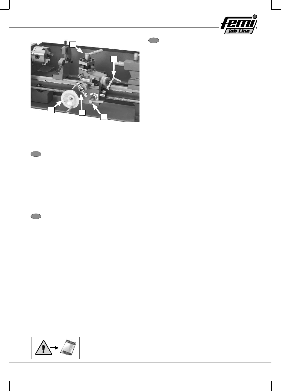
Chariot Fig. 03
H. Tourelle porte-outil à 4 voies : Elle supporte jusqu’à 4 outils de coupe pouvant être indéxés
individuellement avec la pièce à usiner.
I. Volant disque orientable : Il permet d’approcher et éloigner l’outil de la pièce en cours d’usinage
à un angle préétabli du disque orientable.
J. Levier demi-écrou : Il permet d’embrayer/débrayer le demi-écrou pour des opérations de
fi letage ou de tournage automatique.
K. Volant coulisseau transversal : Il permet d’éloigner ou approcher le coulisseau transversal de
la pièce à usiner.
L. Volant chariot : Il permet de déplacer le chariot le long des guides du banc.
EN Carriage Fig. 03
H. 4-way tool post: Holds up to four cutting tools once that can be individually indexed to the
workpiece.
I . Compound Rest Handwheel: Moves the tool toward and away from the workpiece at the
preset angle of the compound rest.
J. Half Nut Lever: Engages/disengages half nut for power feed and threading operations.
K. Cross Slide Handwheel: Moves the cross slide toward and away from the workpiece.
L. Carriage Handwheel: Moves the carriage at along the bedway.
IT Carrello Fig. 03
H. Torretta portautensile a 4 vie: Supporta
fi no a quattro utensili di taglio che
possono essere singolarmente
indicizzati con il pezzo in lavorazione.
I . Volantino disco orientabile: Avvicina
ed allontana l’utensile dal pezzo in
lavorazione ad un angolo preimpostato
del disco orientabile.
J. Leva chiocciola spaccata: Inserisce/
disinserisce la chiocciola spaccata per
operazioni di fi lettatura o di tornitura
automatica.
K. Volantino slitta trasversale: Allontana o
avvicina la slitta trasversale dal pezzo in
lavorazione.
L. Volantino carrello: Muove il carrello
lungo le guide del bancale.

10
O
MN
P
Q
R
S
FR
Corps contre-pointe Fig. 04
M. Fourreau corps contre-pointe : Il permet d’approcher ou éloigner un outil ou une mèche
montés sur le corps contre-pointe de la pièce à usiner.
N. Levier de blocage fourreau corps contre-pointe : Il permet de fi xer la position du fourreau.
O. Levier de blocage corps contre-pointe : Il permet de fi xer en position le corps de la contre-point
le long du guide du banc.
P. Règle graduée : Elle indique le mouvement du fourreau en pas de 0,025 mm, avec un tour
complet égal à 1 mm de course du fourreau.
Q. Volant fourreau : Il permet d’approcher ou éloigner le fourreau de l’arbre du mandrin.
R. Échelle de décalage : Elle indique la distance relative du décalage du corps contre-pointe de
la ligne médiane de l’arbre du mandrin.
S. Vis de décalage corps contre-pointe : Elle permet de régler le décalage du corps contre-pointe
à gauche ou à droite par rapport à la ligne médiane de l’arbre mandrin (1 de 2).
EN Tailstock Fig: 04
M. Tailstock Quill: Moves a tool or center mounted in the tailstock toward or away from the
workpiece.
N. Tailstock Quill Lock lever: Secures the quill position.
O. Tailstock Lock Lever: Secures tailstock in position along the bedway.
P. Graduated Scale: Indicates quill movement in increments of 0.025mm, with one full
revolution equaling 1mm of quill travel.
Q. Quill Handwheel: Moves quill toward or away from spindle.
R. Off set Scale: Indicates relative distance of tailstock off set from spindle centerline.
S. Tailstock Off set Screws: Adjusts tailstock off set left or right from spindle centerline (1 of
2).
IT Corpo Contropunta Fig. 04
M. Canotto corpo contropunta: Avvicina
o allontana un utensile o una punta
montati sul corpo contropunta dal pezzo
in lavorazione.
N. Leva bloccaggio canotto corpo
contropunta: Fissa la posizione del
canotto.
O. Leva bloccaggio corpo contropunta:
Fissa in posizione il corpo contropunta
lungo la guida del bancale
P. Scala graduata: Indica il movimento del
canotto in passi da 0,025mm, con un
giro completo pari a 1mm di corsa del
canotto.
Q. Volantino canotto: Avvicina o allontana il canotto dall’albero del mandrino.
R. Scala di sfalsamento: Indica la distanza relativa dello sfalsamento del corpo contropunta
dalla mezzeria dell’albero del mandrino.
S. Viti sfalsamento corpo contropunta: Regola lo sfalsamento del corpo contropunta a sinistra o
a destra rispetto alla mezzeria dell’albero mandrino (1 di 2).

11
T
U
FR
Commandes arrière Fig. 05
T. Sélecteur vitesse rapide/lente : Il permet de confi gurer la gamme de vitesses de l’arbre du
mandrin sur PETITE (100–1000 tours/min) ou GRANDE (100–2000 tours/min). NE PAS agir
sur le levier avec le tour en fonction, afi n d’éviter d’endommager la machine !
U. Levier inversion-avancement barres : Il est utilisé pour sélectionner le sens de rotation de la
vis-mère. En haut pour une rotation en sens horaire et mouvement du chariot vers la gauche.
Au centre se trouve le point mort. En bas pour une rotation en sens antihoraire de la vis-mère
et mouvement du chariot vers la droite.
Confi guration des engrenages fi naux qui commandent la vitesse de la vis-mère pour des opérations de
fi letage ou de tournage.
EN Rear Controls Fig. 05
T. High/Low Range Lever: Set the spindle speed range to LOW (100–1000 RPM) or HIGH
(100–2000 RPM). Do NOT shift while lathe is running or damage to machine may occur!
U. Feed direction lever: Used to select leadscrew rotation direction. Up is for clock- wise
rotation and leftward carriage movement. Center is neutral. Down is for counter-
clockwise leadscrew rotation and rightward carriage movement.
Confi guring the end gears what controls the speed of the leadscrew for threading or power feed
operations
IT Comandi posteriori Fig. 05
T. Selettore marcia veloce/lenta: Imposta
la gamma di velocità dell’albero del
mandrino su BASSA (100–1000 giri/min)
o ALTA (100–2000 giri/min). NON agire
sulla leva mentre il tornio è in funzione,
o la macchina potrebbe danneggiarsi!
U. Leva inversione-avanzamento barre:
Utilizzata per selezionare il senso di
rotazione della madre vite. In alto per
una rotazione oraria e movimento
verso sinistra del carrello. Centro è la
posizione neutra. In basso per rotazione antioraria della madre vite e movimento verso
destra del carrello.
Confi gurazione degli ingranaggi fi nali che comandano la velocità della madre vite per operazioni
di fi lettatura o di tornitura

12
ABC
D
IJ
K
L
M
N
O
P
Q
H
1
FR
Fig. 06
1. Engrenages
Inventaire
Ci-après est indiquée la liste des pièces expédiées
avec le tour. Avant de commencer l’aménagement, il
est recommandé de sortir les pièces de l’emballage
et d’en eff ectuer un inventaire.
FR
Composants installés
Fig. 7
A. Mandrin à 3 griff es 80 mm .................... 1
B. Couvercle mandrin ................................ 1
C. Couvercle tourelle porte-outil ................ 1
D. Bac à huile ............................................ 1
EN Fig. 06
1. Gears
Inventory
The following is a list of items shipped with your
lathe. Before beginning setup, lay these items
out and inventory time.
EN Installed Components Fig. 7
A. 80mm Three-Jaw Chuck ................... 1
B. Chuck cover....................................... 1
C. Tool post cover .................................. 1
D. Oil tray ............................................... 1
IT
Fig. 06
1. Ingranaggi
Inventario
L’elenco delle parti spedite con il tornio è
riportato qui di seguito. Prima di cominciarne
l’allestimento, disporre le parti fuori dall’imballo
ed eseguire un inventario.
IT Componenti installati Fig. 7
A. Mandrino a 3 griff e 80mm .................. 1
B. Coperchio mandrino .......................... 1
C. Coperchio torretta portautensile ........ 1
D. Vaschetta olio .................................... 1
IT Componenti dell’imballo Fig. 8
H. Set di chiavi esagonali
(2,5, 3, 4, 5, 6mm) ............................. 1
I. Set di chiavi (6/7, 8/10, 13/16mm) ..... 1
J. Contenitore per olio ........................... 1
K. Set griff e esterne per mandrino a 3
griff e ................................................... 1
L. Contropunta fi ssa MT#3 .................... 1
M. Contropunta fi ssa
MT#2……………………..1
N. Fusibile .............................................. 1
O. Maniglia volantino slitta trasversale ... 1
P. Maniglia volantino carrello ................. 1
Q. Chiave mandrino a 3 griff e ................ 1

13
12
1
2
13
4
5
FR
1. Manette de réglage
2. Commutateur de direction arbre
FR
1. Levier de direction avancement
2. Sélecteur marche lente/rapide
3. HAUT (Rotation en sens horaire)
4. CENTRE (Neutre)
5. BAS (Rotation en sens antihoraire)
FR
Contenu de l’emballage
Fig. 8
H. Jeu de clés hexagonales
(2,5, 3, 4, 5, 6mm) ................................. 1
I. Jeu de clés (6/7, 8/10, 13/16 mm) ......... 1
J. Conteneur pour huile ............................. 1
K. Jeu de griff es externes pour man
L. Contre-pointe fi xe MT#3 ........................ 1
M. Contre-pointe fi xe MT#2………………...1
N. Fusible ................................................... 1
O. Poignée volant coulisseau transversal .. 1
P. Poignée volant chariot ........................... 1
Q. Clé mandrin à 3 griff es .......................... 1
EN Contents of the packaging Fig. 8
H. Hex Wrench Set
(2,5, 3, 4, 5, 6mm) ............................. 1
I. Wrench Set (6/7, 8/10, 13/16mm) ..... 1
J. Pot for Oil........................................... 1
K. 3-Jaw Chuck External Jaw Set .......... 1
L. Dead Center MT#3 ............................ 1
M. Dead Center MT#2 ............................ 1
N. Fuse................................................... 1
O. Cross Slide Handwheel Handle ......... 1
P. Carriage Handwheel Handle ............. 1
Q. 3-Jaw Chuck Key............................... 1
EN
1. Adjustment handle
2. Spindle Direction Switch
EN
1. Feed Direction Lever
2. High/Low Range Lever
3. HIGH (clockwise rotation)
4. CENTER (Neutral)
5. DOWN (CCW Rotation)
Fig. 09
IT
1. Manopola regolazione
2. Interruttore direzione albero
Fig. 10
IT
1. Leva direzione avanzamento
2. Selettore marcia veloce/lenta
3. ALTO (Rotazione oraria)
4. CENTRO (Neutro)
5. BASSO (Rotazione antioraria)

14
1
2
3
4
12
3
12
1
2
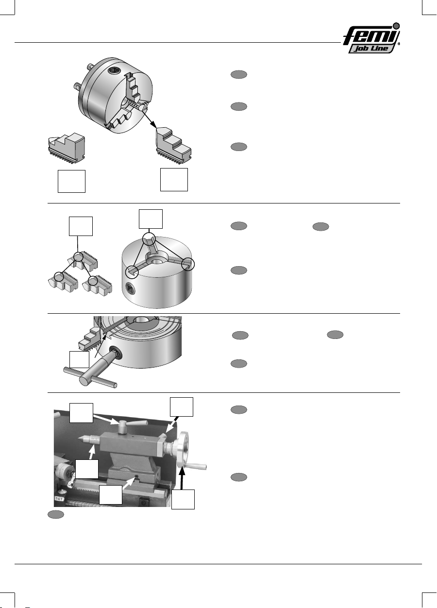
FR
1. Levier demi-écrou
2. Débrayé
3. Levier demi-écrou
4. Embrayé
FR
1. Trous de montage
2. Épaulement de la plaque
3. Conicité interne
FR
1. Contre-plaque mandrin
2. Vis mandrin
FR
1. Écrou hexagonal
2. Rondelle de blocage
EN
1. Half nut lever
2. Disengaged
3. Half nut lever
4. Engaged
EN
1. Mounting Holes
2. Backplate Shoulder
3. Inside Taper
EN
1. Spindle Backplate
2. Chuck Screw
EN
1. Hex Nut
2. Lock Washer
Fig. 11
IT
1. Leva chiocciola spaccata
2. Disinserita
3. Leva chiocciola spaccata
4. Inserita
Fig. 12
IT
1. Fori di montaggio
2. Spalla della piastra
3. Conicità interna
Fig. 13
IT
1. Piastra di spallamento mandrino
2. Vite mandrino
Fig. 14
IT
1. Dado esagonale
2. Rondella di bloccaggio
15
1
1
2
3
1
2
2
1
1
12
5
34
FR
1. Jeu externe
2. Jeu interne
FR
1. Numéros griff es
2. Guides griff es
FR
1. Pas du fi let
FR
1. Levier de blocage fourreau
2. Levier de blocage corps contre-pointe
3. Vis de réglage du décalage (1 de 2)
4. Volant fourreau
5. Fourreau
EN
1. Outside Set
2. Inside Set
EN
1. Jaw Numbers
2. Jaw Guides
EN
1. Lead Thread
EN
1. Quill Lock Lever
2. Tailstock Lock Lever
3. Off set Adjustment Screw (1 of 2)
4. Quill Handwheel
5. Quill
Fig. 15
IT
1. Set esterno
2. Set interno
Fig. 16
IT
1. Numeri griff e
2. Guide griff e
Fig. 17
IT
1. Imbocco del fi letto
Fig. 18
IT
1. Leva bloccaggio canotto
2. Leva bloccaggio corpo contropunta
3. Vite regolazione sfalsamento (1 di 2)
4. Volantino canotto
5. Canotto

16
1
3
2
1
2
1
3
1
FR
1. Volant chariot
2. Volant disque orientable
3. Volant coulisseau
FR
1. Sélecteur vitesse rapide/lente
FR
1. Affi cheur vitesse arbre mandrin
2. Manette de réglage vitesse
3. Interrupteur
FR
1. Levier de direction avancement
EN
1. Carriage Handwheel
2. Compound Rest Handwheel
3. Slide handwheel
EN
1. High/Low range lever
EN
1. Spindle Speed Display
2. Speed adjusting knob
3. Switch
EN
1. Feed Direction Lever
Fig. 19
IT
1. Volantino carrello
2. Volantino disco orientabile
3. Volantino slitta
Fig. 20
IT
1. Selettore marcia veloce/lenta
Fig. 21
IT
1. Display velocità albero mandrino
2. Manopola regolazione velocità
3. Interruttore
Fig. 22
IT
1. Leva direzione avanzamento

17
C
B
A
D
A (20T)
B (80T)
D (80T)
C (20T)
B
A
C
D
1
12
3
4
1
2
34
FR
1. Levier demi-écrou
FR
2. Engrenage A (20T)
3. Engrenage C (20T)
4. Engrenage D (80T)
5. Engrenage B (80T)
FR
1. Engrenage B/C
2. Vis à tête creuse
3. Écrou hexagonal
4. Engrenage D
EN
1. Half nut lever
EN
2. A Gear (20T)
3. C Gear (20T)
4. D Gear (80T)
5. B Gear (80T)
EN
1. B/C Gear
2. Cap Screws
3. Hex Nut
4. D Gear
Fig. 23
IT
1. Leva chiocciola spaccata
Fig. 24
Fig. 25
IT
1. Ingranaggio A (20T)
2. Ingranaggio C (20T)
3. Ingranaggio D (80T)
4. Ingranaggio B (80T)
Fig. 26
IT
1. Ingranaggio B/C
2. Viti a testa incassata
3. Dado esagonale
4. Ingranaggio D
18
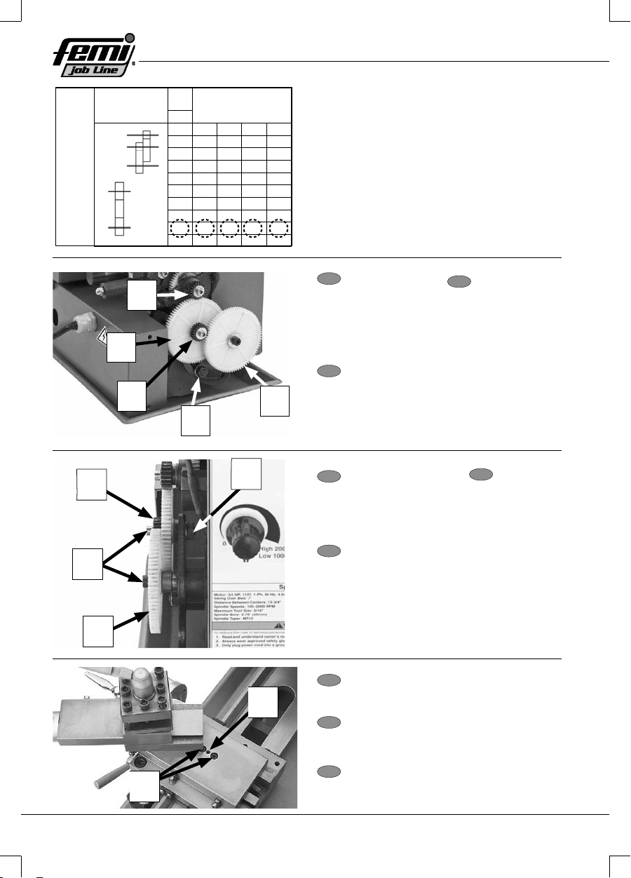
A
PITCH
MM
ABCD
0.540603060
0.735604050
0.840604050
160453060
1.25 40 60 50 40
1.540606040
1.75 35 60 60 30
2 60505045
2.550606030
STUD
GEAR
BOX
STUD
GEAR
BOX
A
B
C
D
A
B
D
2
1
3
54
14
2
3
2
1
FR
1. Engrenage A
2. Engrenage B
3. Engrenage C
4. Engrenage D
5. Écrou hexagonal de réglage
FR
1. Engrenage B/C
2. Vis à tête creuse
3. Engrenage D
4. Écrou hexagonal
FR
1. Vis à tête creuse externes
2. Vis à tête creuse internes
EN
1. A Gear
2. B Gear
3. C Gear
4. D Gear
5. Adjuster Hex Nut
EN
1. B/C Gear
2. Cap Screws
3. D Gear
4. Hex Nut
EN
1. Outer Cap Screws
2. Inner Cap Screw
Fig. 27
Fig. 28
IT
1. Ingranaggio A
2. Ingranaggio B
3. Ingranaggio C
4. Ingranaggio D
5. Dado esagonale
regolazione
Fig. 29
IT
1. Ingranaggio B/C
2. Viti a testa incassata
3. Ingranaggio D
4. Dado esagonale
Fig. 30
IT
1. Viti a testa incassata esterne
2. Vite a testa incassata interna

19
1
3
2
4
1
2
13
1
FR
1. Vis-mère
2. Bride de support
3. Écrou à colonne
4. Vis à grain
FR
1. Dispositifs de réglage du coulisseau
transversal
FR
1. Dispositifs de réglage du coulisseau
porte-outil
FR
1. Clavette
2. Demi-écrou
3. Vis à grain
EN
1. Leadscrew
2. End Bracket
3. Retaining Nut
4. Set Screw
EN
1. Cross Slide Adjustment Fasteners
EN
1. Top Slide Adjustment Fasteners
EN
1. Gib
2. Half nut
3. Set Screw
Fig. 31
IT
1. Madre vite
2. Staff a di supporto
3. Dado a colonna
4. Vite a grano
Fig. 32
IT
1. Bloccaggi di regolazione della Slitta
trasversale
Fig. 33
IT
1. Bloccaggi di regolazione della Slitta porta
utensile
Fig. 34
IT
1. Perno
2. Chiocciola
3. Vite a grano

20
Cap
3
12
12
1
1
2
1
FR
1. Porte-fusible
2. Fusible
3. Trou porte-fusible
FR
1. Vis
2. Capuchon balai
FR
1. Balai
FR
1. Capuchon balai
2. Balai
EN
1. Fuse Holder
2. Fuse
3. Fuse Holder Hole
EN
1. Screws
2. Brush Cap
EN
1. Brush
EN
1. Brush Cap
2. Brush
Fig. 35
IT
1. Porta fusibile
2. Fusibile
3. Foro porta fusibile
Fig. 36
IT
1. Viti
2. Cappellotto spazzola
Fig. 37
IT
1. Spazzola
Fig. 38
IT
1. Cappellotto spazzola
2. Spazzola
Other manuals for JOB LINE DIGITO ML 350
1
This manual suits for next models
1
Table of contents
Other Femi Lathe manuals


